

INSTRUCTION MANUAL
MANUEL D'INSTRUCTION
MANUAL DE INSTRUCCIONES
Angle Grinder
Meuleuse d'Angle
Esmeriladora de Disco
9560CV
9561C/9561CV
9564C/9564CV
9565CV
IMPORTANT: Read Before Using.
IMPORTANT: Lire avant usage.
IMPORTANTE: Leer antes de usar.
004055
DOUBLE INSULATION
DOUBLE ISOLATION
DOBLE AISLAMIENTO
1

ENGLISH (Original instructions)
SPECIFICATIONS
Model 9560CV 9561C 9561CV 9564C 9564CV 9565CV
Wheel diameter 100 mm (4")
Spindle thread M10 x 1.25 5/8" 5/8" 5/8" 5/8" 5/8"
No load speed (RPM)
Overall length 289 mm (11 - 3/8") 299 mm (11 - 3/4")
Net weight
• Due to our continuing program of research and development, the specifications herein are subject to change without notice.
• Specifications may differ from country to country.
• Weight according to EPTA-Procedure 01/2003
2,800 - 10,500
2.1 kg (4.7 lbs)
GENERAL SAFETY RULES
(For All Tools)
WARNING! Read and understand all instructions.
Failure to follow all instructions listed below, may result in
electric shock, fire and/or serious personal injury.
SAVE THESE INSTRUCTIONS.
Work Area
1. Keep your work area clean and well lit.
Cluttered benches and dark areas invite
accidents.
2. Do not operate power tools in explosive
atmospheres, such as in the presence of
flammable liquids, gases or dust. Power tools
create sparks which may ignite the dust or fumes.
3. Keep bystanders, children, and visitors away
while operating a power tool. Distractions can
cause you to lose control.
Electrical safety
4. Double insulated tools are equipped with a
polarized plug ( one blade is wider than the
other.) This plug will fit in a polarized outlet
only one way. If the plug does not fit fully in
the outlet, reverse the plug. If it still does not
fit, contact a qualified electrician to install a
polarized outlet. Do not change the plug in any
way. Double insulation
the three wire grounded power cord and grounded
power supply system.
5. Avoid body contact with grounded surfaces
such as pipes, radiators, ranges and
refrigerators. There is an increased risk of
electric shock if your body is grounded.
6. Do not expose power tools to rain or wet
conditions. Water entering a power tool will
increase the risk of electric shock.
7.
Do not abuse the cord. Never use the cord to carry
the tools or pull the plug from an outlet. Keep cord
eliminates the need for
115 mm (4-1/2") 115 mm (4-1/2") 115 mm (4-1/2") 115 mm (4-1/2")
10,500
2,800 - 10,500
2.2 kg (4.9 lbs)
USA002-2
10,500
2.3 kg (5.0 lbs) 2.3 kg (5.0 lbs) 2.4 kg (5.2 lbs)
2,800 - 10,500 2,800 - 10,500
away from heat, oil, sharp edges or moving parts.
Replace damaged cords immediately.
cords increase the risk of electric shock.
8. When operating a power tool outside, use an
outdoor extension cord marked "W-A" or "W".
These cords are rated for outdoor use and reduce
the risk of electric shock.
Personal safety
9. Stay alert, watch what you are doing and use
common sense when operating a power tool.
Do not use tool while tired or under the
influence of drugs, alcohol, or medication. A
moment of inattention while operating power tools
may result in serious personal injury.
10. Dress properly. Do not wear loose clothing or
jewelry. Contain long hair. Keep your hair,
clothing, and gloves away from moving parts.
Loose clothes, jewelry, or long hair can be caught
in moving parts.
11. Avoid accidental starting. Be sure switch is off
before plugging in. Carrying tools with your
finger on the switch or plugging in tools that have
the switch on invites accidents.
12. Remove adjusting keys or wrenches before
turning the tool on. A wrench or a key that is left
attached to a rotating part of the tool may result in
personal injury.
13. Do not overreach. Keep proper footing and
balance at all times. Proper footing and balance
enables better control of the tool in unexpected
situations.
14. Use safety equipment. Always wear eye
protection. Dust mask, non-skid safety shoes,
hard hat, or hearing protection must be used for
appropriate conditions. Ordinary eye or sun
glasses are NOT eye protection.
Tool Use and Care
15. Use clamps or other practical way to secure
and support the workpiece to a stable platform.
Holding the work by hand or against your body is
unstable and may lead to loss of control.
2
125 mm (5")
Damaged

16. Do not force tool. Use the correct tool for your
application. The correct tool will do the job better
and safer at the rate for which it is designed.
17. Do not use tool if switch does not turn it on or
off. Any tool that cannot be controlled with the
switch is dangerous and must be repaired.
18. Disconnect the plug from the power source
before making any adjustments, changing
accessories, or storing the tool. Such
preventive safety measures reduce the risk of
starting the tool accidentally.
19. Store idle tools out of reach of children and
other untrained persons. Tools are dangerous in
the hands of untrained users.
20. Maintain tools with care. Keep cutting tools
sharp and clean. Properly maintained tools with
sharp cutting edges are less likely to bind and are
easier to control.
21. Check for misalignment or binding of moving
parts, breakage of parts, and any other
condition that may affect the tool’s operation.
If damaged, have the tool serviced before
using. Many accidents are caused by poorly
maintained tools.
22. Use only accessories that are recommended
by the manufacturer for your model.
Accessories that may be suitable for one tool, may
become hazardous when used on another tool.
Service
23. Tool service must be performed only by
qualified repair personnel. Service or
maintenance performed by unqualified personnel
could result in a risk of injury.
24. When servicing a tool, use only identical
replacement parts. Follow instructions in the
Maintenance section of this manual. Use of
unauthorized parts or failure to follow Maintenance
instructions may create a risk of electric shock or
injury.
USE PROPER EXTENSION CORD. Make sure your
extension cord is in good condition. When using an
extension cord, be sure to use one heavy enough to
carry the current your product will draw. An
undersized cord will cause a drop in line voltage
resulting in loss of power and overheating. Table 1
shows the correct size to use depending on cord
length and nameplate ampere rating. If in doubt, use
the next heavier gage. The smaller the gage number,
the heavier the cord.
Table 1: Minimum gage for cord
Ampere Rating
Volts Total length of cord in feet
120 V 25 ft. 50 ft. 100 ft. 150 ft.
More Than Not More Than AWG
0 6 18 16 16 14
18 16 14 12610
10 12 16 16 14 12
000173
SPECIFIC SAFETY RULES
DO NOT let comfort or familiarity with product
(gained from repeated use) replace strict adherence
to grinder safety rules. If you use this tool unsafely
or incorrectly, you can suffer serious personal
injury.
1. Always use proper guard with grinding wheel.
2. Accessories must be rated for at least the
3. Hold tool by insulated gripping surfaces when
12 16 14 12
USB005-4
A guard protects operator from broken wheel
fragments.
speed recommended on the tool warning label.
Wheels and other accessories running over rated
speed can fly apart and cause injury.
performing an operation where the cutting tool
may contact hidden wiring or its own cord.
Contact with a "live" wire will make exposed metal
parts of the tool "live" and shock the operator.
4.
When using depressed center grinding wheels,
be sure to use only fiberglass-reinforced wheels.
5. Always use safety glasses or goggles.
Ordinary eye or sun glasses are NOT safety
glasses.
6. Check the wheel carefully for cracks or
damage before operation. Replace cracked or
damaged wheel immediately. Run the tool
(with guard) at no load for about a minute,
holding tool away from others. If wheel is
flawed, it will likely separate during this test.
7. Use only flanges specified for this tool.
8. Be careful not to damage the spindle, the
flange (especially the installing surface) or the
lock nut. Damage to these parts could result in
wheel breakage.
3
Not Recommended

9. NEVER use tool with wood cutting blades or
other sawblades. Such blades when used on a
grinder frequently kick and cause loss of
control leading to personal injury.
10. Hold the tool firmly.
11. Keep hands away from rotating parts.
12. Make sure cord is clear of wheel. Do not wrap
cord around your arm or wrist. If control of
tool is lost, cord may become wrapped around
you and cause personal injury.
13. Make sure the wheel is not contacting the
workpiece before the switch is turned on.
14. Before using the tool on an actual workpiece,
let it run for a while. Watch for vibration or
wobbling that could indicate poor installation
or a poorly balanced wheel.
15. Use the specified surface of the wheel to
perform the grinding.
16. Watch out for flying sparks. Hold the tool so
that sparks fly away from you and other
persons or flammable materials.
17. Do not leave the tool running. Operate the tool
only when hand-held.
18. Do not touch the workpiece immediately after
operation; it may be extremely hot and could
burn your skin.
19. ALWAYS wear proper apparel including long
sleeve shirts, leather gloves and shop aprons
to protect skin from contact with hot
grindings.
20. Use of this tool to grind or sand some
products, paints and wood could expose user
to dust containing hazardous substances. Use
appropriate respiratory protection.
21. After using the tool, make sure the wheel
rotation comes to a complete stop before
setting the tool down. Setting the tool down
with the wheel rotating can cause personal
injury.
SAVE THESE INSTRUCTIONS.
WARNING:
MISUSE or failure to follow the safety rules stated in
this instruction manual may cause serious personal
injury.
Symbols
The followings show the symbols used for tool.
・ volts
・ amperes
・ hertz
・ alternating current
・ no load speed
・ Class II Construction
・ revolutions or reciprocation per minute
4
USD201-2
FUNCTIONAL DESCRIPTION
CAUTION:
• Always be sure that the tool is switched off and
unplugged before adjusting or checking function on
the tool.
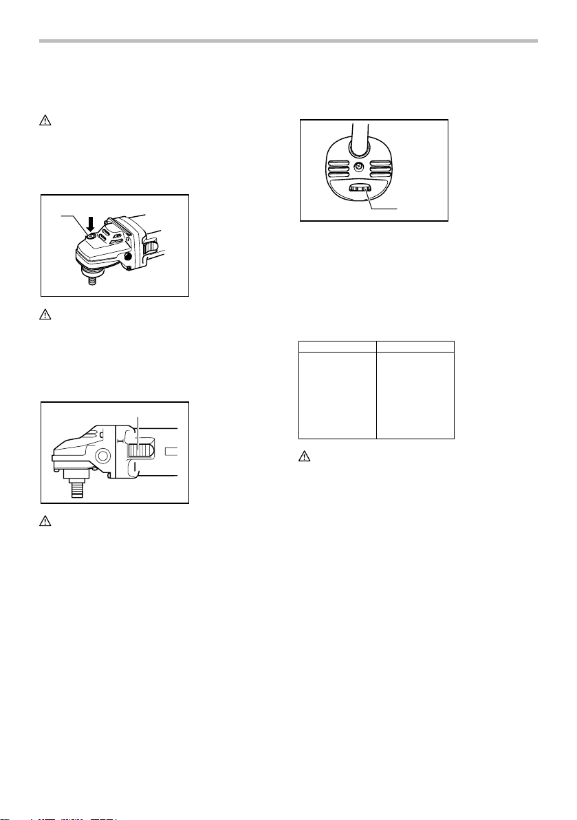
Shaft lock
1
002978
CAUTION:
• Never actuate the shaft lock when the spindle is
moving. The tool may be damaged.
Press the shaft lock to prevent spindle rotation when
installing or removing accessories.
Switch action
1
001035
CAUTION:
• Before plugging in the tool, always check to see
that the slide switch actuates properly and returns
to the "OFF" position when the rear of the slide
switch is depressed.
• Switch can be locked in "ON" position for ease of
operator comfort during extended use. Apply
caution when locking tool in "ON" position and
maintain firm grasp on tool.
To start the tool, slide the slide switch toward the "I (ON)"
position. For continuous operation, press the front of the
slide switch to lock it.
To stop the tool, press the rear of the slide switch, then
slide it toward the "O (OFF)" position.
1. Shaft lock
1. Slide switch
O
Speed adjusting dial
For model 9560CV, 9561CV, 9564CV, 9565CV only
1. Speed adjusting
dial
2
1
001046
The rotating speed can be changed by turning the speed
adjusting dial to a given number setting from 1 to 5.
Higher speed is obtained when the dial is turned in the
direction of number 5. And lower speed is obtained when
it is turned in the direction of number 1.
Refer to the below table for the relationship between the
number settings on the dial and the approximate rotating
speed.
001279
Number
1
|
2
|
3
|
4
|
5
RPM (/min)
2,800
|
4,000
|
6,500
|
9,000
|
10,500
CAUTION:
• If the tool is operated continuously at low speeds
for a long time, the motor will get overloaded and
heated up.
• The speed adjusting dial can be turned only as far
as 5 and back to 1. Do not force it past 5 or 1, or the
speed adjusting function may no longer work.
The tools equipped with electronic function are easy to
operate because of the following features.
Electronic function
Constant speed control
• Possible to get fine finish, because the rotating
speed is kept constant even under the loaded
condition.
• Additionally, when the load on the tool exceeds
admissible levels, power to the motor is reduced to
protect the motor from overheating. When the load
returns to admissible levels, the tool will operate as
normal.
Soft start feature
• Soft start because of suppressed starting shock.
5
ASSEMBLY
CAUTION:
• Always be sure that the tool is switched off and
unplugged before carrying out any work on the tool.
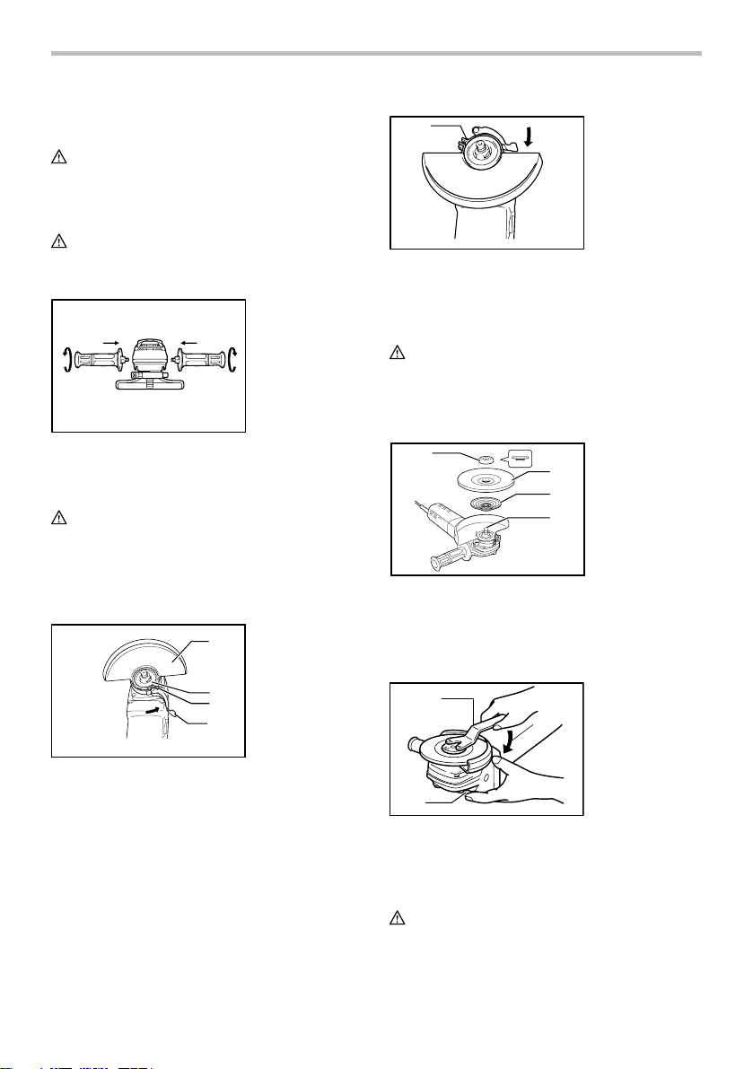
Installing side grip (handle)
CAUTION:
• Always be sure that the side grip is installed
securely before operation.
1
2
3
4
1. Wheel guard
2. Bearing box
3. Screw
4. Lever
002979
Screw the side grip securely on the position of the tool as
shown in the figure.
Installing or removing wheel guard
CAUTION:
• When using a depressed center grinding
wheel/Multi-disc, flex wheel, wire wheel brush or
cut-off wheel, the wheel guard must be fitted on the
tool so that the closed side of the guard always
points toward the operator.
1
002981
1. Screw
To remove wheel guard, follow the installation procedure
in reverse.
Installing or removing depressed center
grinding wheel/Multi-disc
WARNING:
• Always use supplied guard when depressed center
grinding wheel/Multi-disc is on tool. Wheel can
shatter during use and guard helps to reduce
chances of personal injury.
1
002982
Mount the inner flange onto the spindle. Fit the wheel/disc
on the inner flange and screw the lock nut onto the spindle.
To tighten the lock nut, press the shaft lock firmly so that
the spindle cannot revolve, then use the lock nut wrench
and securely tighten clockwise.
1
1. Lock nut
2. Depressed
2
3
4
center grinding
wheel/Multi-disc
3. Inner flange
4. Spindle
1. Lock nut wrench
2. Shaft lock
002980
Loosen the lever on the wheel guard. Mount the wheel
guard with the protrusion on the wheel guard band
aligned with the notch on the bearing box. Then rotate
the wheel guard around 180 degrees. Tighten the lever
to fasten the wheel guard. If the lever is too tight or too
loosen to fasten the wheel guard, loosen or tighten the
screw to adjust the tightening of the wheel guard band.
2
001084
To remove the wheel, follow the installation procedure in
reverse.
Installing or removing flex wheel
(optional accessory)
WARNING:
• Always use supplied guard when flex wheel is on
tool. Wheel can shatter during use and guard helps
to reduce chances of personal injury.
6
1. Lock nut
1
2. Flex wheel
2
3. Plastic pad
3
4. Inner flange
4
001096
Follow instructions for depressed center grinding
wheel/Multi-disc but also use plastic pad over wheel. See
order of assembly on accessories page in this manual.
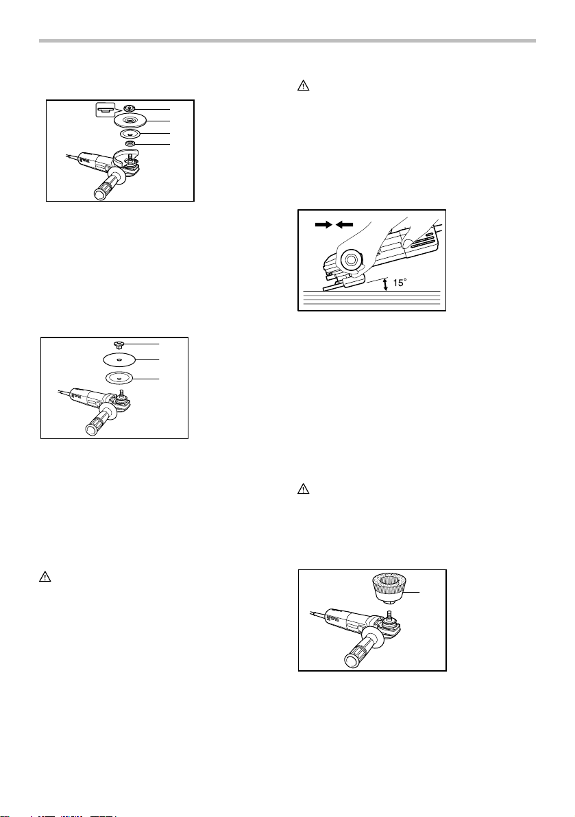
Installing or removing abrasive disc
(optional accessory)
NOTE:
• Use sander accessories specified in this manual.
These must be purchased separately.
1. Lock nut
1
2. Abrasive disc
2
3. Rubber pad
3
001107
Mount the rubber pad onto the spindle. Fit the disc on the
rubber pad and screw the lock nut onto the spindle. To
tighten the lock nut, press the shaft lock firmly so that the
spindle cannot revolve, then use the lock nut wrench and
securely tighten clockwise.
To remove the disc, follow the installation procedure in
reverse.
OPERATION
WARNING:
• It should never be necessary to force the tool. The
weight of the tool applies adequate pressure.
Forcing and excessive pressure could cause
dangerous wheel breakage.
•
ALWAYS replace wheel if tool is dropped while grinding.
• NEVER bang or hit grinding disc or wheel onto
work.
• Avoid bouncing and snagging the wheel, especially
when working corners, sharp edges etc. This can
cause loss of control and kickback.
• NEVER use tool with wood cutting blades and other
sawblades. Such blades when used on a grinder
frequently kick and cause loss of control leading to
personal injury.
CAUTION:
• Never switch on the tool when it is in contact with
the workpiece, it may cause an injury to operator.
• Always wear safety goggles or a face shield during
operation.
• After operation, always switch off the tool and wait
until the wheel has come to a complete stop before
putting the tool down.
Grinding and sanding operation
AB
002983
ALWAYS hold the tool firmly with one hand on housing
and the other on the side handle. Turn the tool on and
then apply the wheel or disc to the workpiece.
In general, keep the edge of the wheel or disc at an angle
of about 15 degrees to the workpiece surface.
During the break-in period with a new wheel, do not work
the grinder in the B direction or it will cut into the
workpiece. Once the edge of the wheel has been
rounded off by use, the wheel may be worked in both A
and B direction.
Operation with wire cup brush
(optional accessory)
CAUTION:
•
Check operation of brush by running tool with no load,
insuring that no one is in front of or in line with brush.
•
Do not use brush that is damaged, or which is out of
balance. Use of damaged brush could increase potential
for injury from contact with broken brush wires.
1. Wire cup brush
1
001136
Unplug tool and place it upside down allowing easy
access to spindle. Remove any accessories on spindle.
Thread wire cup brush onto spindle and tighten with
supplied wrench. When using brush, avoid applying too
much pressure which causes over bending of wires,
leading to premature breakage.
7
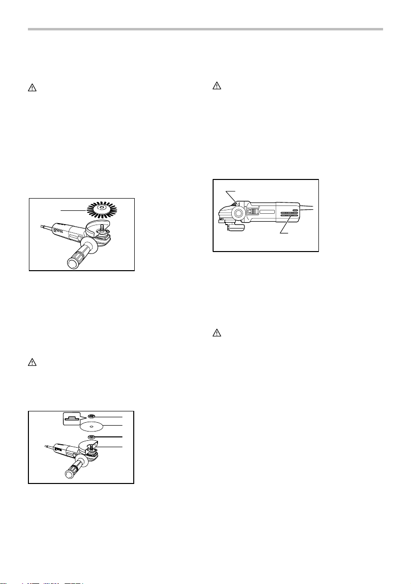
Operation with wire wheel brush
(optional accessory)
CAUTION:
• Check operation of wire wheel brush by running
tool with no load, insuring that no one is in front of
or in line with the wire wheel brush.
• Do not use wire wheel brush that is damaged, or
which is out of balance. Use of damaged wire
wheel brush could increase potential for injury from
contact with broken wires.
• ALWAYS use guard with wire wheel brushes,
assuring diameter of wheel fits inside guard. Wheel
can shatter during use and guard helps to reduce
chances of personal injury.
1
1. Wire wheel
brush
MAINTENANCE
CAUTION:
• Always be sure that the tool is switched off and
unplugged before attempting to perform inspection
or maintenance.
• Never use gasoline, benzine, thinner, alcohol or the
like. Discoloration, deformation or cracks may
result.
The tool and its air vents have to be kept clean. Regularly
clean the tool's air vents or whenever the vents start to
become obstructed.
1
2
1. Exhaust vent
2. Inhalation vent
001229
Unplug tool and place it upside down allowing easy access
to spindle. Remove any accessories on spindle. Thread wire
wheel brush onto spindle and tighten with the wrenches.
When using wire wheel brush, avoid applying too much
pressure which causes over bending of wires, leading to
premature breakage.
Operation with abrasive cut-off wheel
(optional accessory)
WARNING:
• When using an abrasive cut-off wheel, be sure to
use only the special wheel guard designed for use
with cut-off wheels.
• NEVER use cut-off wheel for side grinding.
1. Lock nut
1
2. Abrasive cut-off
2
wheel
3
3. Inner flange
4
4. Wheel guard for
cut-off wheel
001618
During cutting operations, never change the angle of the
wheel. Placing side pressure on the cut-off wheel (as in
grinding) will cause the wheel to crack and break,
causing serious personal injury.
002985
To maintain product SAFETY and RELIABILITY, repairs,
carbon brush inspection and replacement, any other
maintenance or adjustment should be performed by
Makita Authorized or Factory Service Centers, always
using Makita replacement parts.
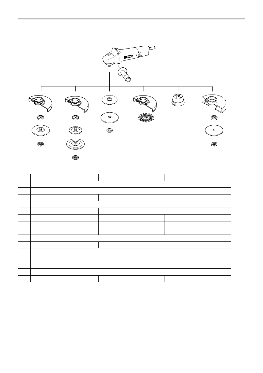
OPTIONAL ACCESSORIES
CAUTION:
• These accessories or attachments are
recommended for use with your Makita tool
specified in this manual. The use of any other
accessories or attachments might present a risk of
injury to persons. Only use accessory or
attachment for its stated purpose.
• Your tool is supplied with a guard for use with a
depressed center grinding wheel, multi-disc, flex
wheel and wire wheel brush. A cut-off wheel can
also be used with an optional guard. If you decide
to use your Makita grinder with approved
accessories which you purchase from your Makita
distributor or factory service center, be sure to
obtain and use all necessary fasteners and guards
as recommended in this manual. Your failure to do
so could result in personal injury to you and others.
If you need any assistance for more details regarding
these accessories, ask your local Makita Service Center.
8
1
2
3
4 14
5
22
6
10
8
9
11
12 13
7
33
5
5
001180
9560CV 9561C/9561CV/9564C/9564CV 9565CV
1
2
3 Inner flange 35
4
5 Lock nut 10-35
Depressed center grinding wheel/Multi-disc
Grip 36
Wheel guard
Inner flange 45
Lock nut 5/8-45
6 Plastic pad - N/A
7 Flex wheel - N/A
8 Rubber pad 76 Rubber pad 100 Rubber pad 115
9
10 Sanding lock nut 10-30
11
12
13
14
- Lock nut wrench 20 Lock nut wrench 28 Lock nut wrench 28
0111 91
NOTE:
• Some items in the list may be included in the tool
package as standard accessories. They may differ
from country to country.
Abrasive disc
Sanding lock nut 5/8-48
Wire wheel brush
Wire cup brush
Wheel guard (For cut-off wheel)
Cut-off wheel
9

MAKITA LIMITED ONE YEAR WARRANTY
Warranty Policy
Every Makita tool is thoroughly inspected and tested
before leaving the factory. It is warranted to be free of
defects from workmanship and materials for the period
of ONE YEAR from the date of original purchase.
Should any trouble develop during this one year period,
return the COMPLETE tool, freight prepaid, to one of
Makita’s Factory or Authorized Service Centers. If
inspection shows the trouble is caused by defective
workmanship or material, Makita will repair (or at our
option, replace) without charge.
This Warranty does not apply where:
repairs have been made or attempted by others:
repairs are required because of normal wear and
tear:
the tool has been abused, misused or improperly
maintained:
alterations have been made to the tool.
IN NO EVENT SHALL MAKITA BE LIABLE FOR ANY
INDIRECT, INCIDENTAL OR CONSEQUENTIAL
DAMAGES FROM THE SALE OR USE OF THE
PRODUCT. THIS DISCLAIMER APPLIES BOTH
DURING AND AFTER THE TERM OF THIS
WARRANTY.
MAKITA DISCLAIMS LIABILITY FOR ANY IMPLIED
WARRANTIES, INCLUDING IMPLIED WARRANTIES
OF "MERCHANTABILITY" AND "FITNESS FOR A
SPECIFIC PURPOSE," AFTER THE ONE YEAR TERM
OF THIS WARRANTY.
This Warranty gives you specific legal rights, and you
may also have other rights which vary from state to
state. Some states do not allow the exclusion or
limitation of incidental or consequential damages, so
the above limitation or exclusion may not apply to you.
Some states do not allow limitation on how long an
implied warranty lasts, so the above limitation may not
apply to you.
EN0006-1
10
 Loading...