

Page 1
GB Angle Grinder Instruction Manual
F Meuleuse d’angle Manuel d’instructions
D Winkelschleifer Betriebsanleitung
I Smerigliatrice angolare Istruzioni per l’uso
NL Haakse slijpmachine Gebruiksaanwijzing
E Amoladora Manual de instrucciones
P Rebarbadora Manual de instruções
DK Vinkelsliber Brugsanvisning
S Vinkelslipmaskin Bruksanvisning
N Vinkelsliper Bruksanvisning
SF Kulmahiomakone Käyttöohje
GR Γωνιακς Λειαντήρας Οδηγίες χρήσεως
9556NB
9557NB
9558NB
Page 2
2
1
12
9556NB
4
3
5
34
9557NB/9558NB
3
4
5
6
7
8
56
9
15˚
10
A
B
78
2
Page 3
11
12
9
Symbols
The followings show the symbols used for the tool. Be sure that you understand their meaning before use.
Symboles
Nous donnons ci-dessous les symboles utilisés pour l’outil. Assurez-vous que vous en avez bien compris la signification avant d’utiliser l’outil.
Symbole
Die folgenden Symbole werden für die Maschine verwendet. Machen Sie sich vor der Benutzung unbedingt mit ihrer
Bedeutung vertraut.
Simboli
Per questo utensile vengono usati i simboli seguenti. Bisogna capire il loro significato prima di usare l’utensile.
Symbolen
Voor dit gereedschap worden de volgende symbolen gebruikt. Zorg ervoor dat u de betekenis van deze symbolen
begrijpt alvorens het gereedschap te gebruiken.
Símbolos
A continuación se muestran los símbolos utilizados con esta herramienta. Asegúrese de que entiende su significado
antes de usarla.
Símbolos
O seguinte mostra os símbolos utilizados para a ferramenta. Certifique-se de que compreende o seu significado antes
da utilização.
Symboler
Nedenstående symboler er anvendt i forbindelse med denne maskine. Vær sikker på, at De har forstået symbolernes
betydning, før maskinen anvendes.
Symboler
Det följande visar de symboler som används för den här maskinen. Se noga till att du förstår deras innebörd innan
maskinen används.
Symbolene
Følgende viser de symblene som brukes for maskinen. Det er viktig å forstå betydningen av disse før maskinen tas i
bruk.
Symbolit
Alla on esitetty koneessa käytetyt symbolit. Opettele näiden merkitys, ennen kuin käytät konetta.
Σύµβολα
Τα ακλουθα δείχνουν τα σύµβολα που χρησιµοποιούνται για το µηχάνηµα. Βεβαιωθείτε τι καταλαβαίνετε
τη σηµασία τους πριν απ τη χρήση.
3
Page 4

❏ Read instruction manual.
❏ Lire le mode d’emploi.
❏ Bitte Betriebsanleitung lesen.
❏ Leggete il manuale di istruzioni.
❏ Lees de gebruiksaanwijzing.
❏ Lea el manual de instrucciones.
❏ Leia o manual de instruções.
❏ Læs brugsanvisningen.
❏ Läs bruksanvisningen.
❏ Les bruksanvisingen.
❏ Katso käyttöohjeita.
❏ ∆ιαβάστε τις οδηγίες χρήσης.
❏ DOUBLE INSULATION
❏ DOUBLE ISOLATION
❏ DOPPELT SCHUTZISOLIERT
❏ DOPPIO ISOLAMENTO
❏ DUBBELE ISOLATIE
❏ DOBLE AISLAMIENTO
❏ Wear safety glasses.
❏ Porter des lunettes de protection.
❏ Schutzbrille tragen.
❏ Indossare occhiali di protezione.
❏ Draag een veiligheidsbril.
❏ Póngase gafas de seguridad.
❏ DUPLO ISOLAMENTO
❏ DOBBELT ISOLERET
❏ DUBBEL ISOLERING
❏ DOBBEL ISOLERING
❏ KAKSINKERTAINEN ERISTYS
❏ ∆ΙΠΛΗ ΜΟΝΩΣΗ
❏ Utilize óculos de segurança.
❏ Bær sikkerhedsbriller.
❏ Bär skyddsglasögon.
❏ Bruk vernebriller.
❏ Käytä suojalaseja.
❏ Φορέστε γυαλιά ασφαλείας.
4
Page 5

ENGLISH
Explanation of general view
1 Shaft lock
2 Switch lever
3 Wheel guard
4 Screw
5 Bearing box
SPECIFICATIONS
Model 9556NB 9557NB 9558NB
Depressed center wheel diamiter ...........................100 mm 115 mm 125 mm
Spindle thread ....................................................... M10 M14 M14
No load speed (min
Overall length ........................................................ 271 mm 271 mm 271 mm
Net weight ..............................................................1.6 kg 1.6 kg 1.6 kg
Safety class ........................................................... /II /II /II
-1
) ............................................11,000 11,000 11,000
6 Lock nut
7 Depressed center grinding
wheel/ Multi-disc
8 Inner flange
9 Lock nut wrench
10 Shaft lock
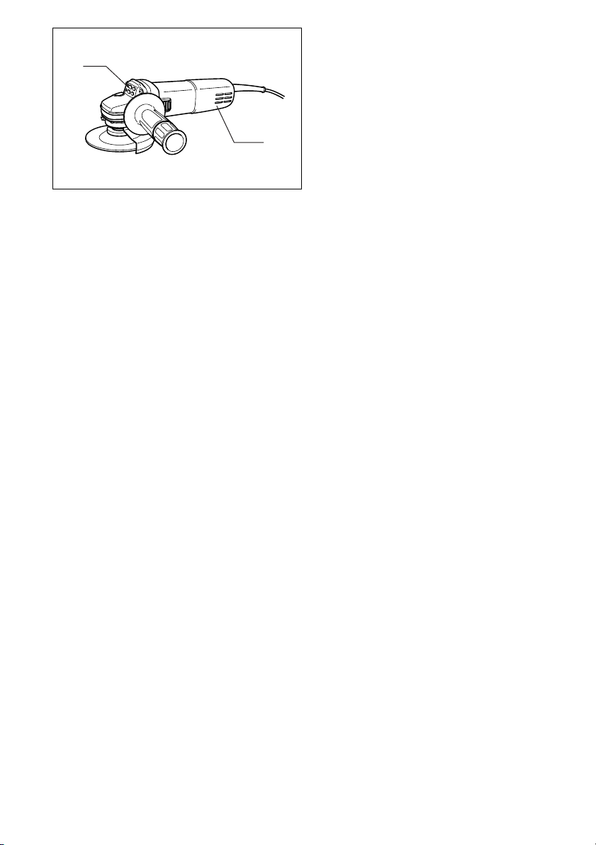
11 Exhaust vent
12 Inhalation vent
• Due to our continuing program of research and development, the specifications herein are subject to change
without notice.
• Note: Specifications may differ from country to country.
Intended use
The tool is intended for cutting, grinding and sanding of
metal and stone materials without the use of water.
Power supply
The tool should be connected only to a power supply of
the same voltage as indicated on the nameplate, and can
only be operated on single-phase AC supply. They are
double-insulated in accordance with European Standard
and can, therefore, also be used from sockets without
earth wire.
Safety hints
For your own safety, please refer to the enclosed safety
instructions.
ADDITIONAL SAFETY RULES
1. Always use eye and ear protection. Other per-
sonal protective equipment such as dust mask,
gloves, helmet and apron should be worn.
2. Always be sure that the tool is switched off and
unplugged before carrying out any work on the
tool.
3. Keep guards in place.
4. Use only wheels with correct size and wheels
having a maximum operating speed at least as
high as the highest No Load Speed marked on
the tool’s nameplate. When using depressed
center wheels, be sure to use only fiberglassreinforced wheels.
5. Check the wheel carefully for cracks or damage
before operation. Replace cracked or damaged
wheel immediately.
6. Observe the instructions of the manufacturer for
correct mounting and use of wheels. Handle and
store wheels with care.
7. Do not use separate reducing bushings or adap-
tors to adapt large hole abrasive wheels.
8. Use only flanges specified for this tool.
9. Do not damage the spindle, the flange (espe-
cially the installing surface) or the lock nut. Damage to these parts could result in wheel
breakage.
ENB031-6
10. For tools intended to be fitted with threaded hole
wheel, ensure that the thread in the wheel is long
enough to accept the spindle length.
11. Before using the tool on an actual workpiece,
test run the tool at the highest no load speed for
at least 30 seconds in a safe position. Stop
immediately if there is any vibration or wobbling
that could indicate poor installation or a poorly
balanced wheel. Check the tool to determine the
cause.
12. Check that the workpiece is properly supported.
13. Hold the tool firmly.
14. Keep hands away from rotating parts.
15. Make sure the wheel is not contacting the workpiece before the switch is turned on.
16. Use the specified surface of the wheel to perform the grinding.
17. Do not use cutting off wheel for side grinding.
18. Watch out for flying sparks. Hold the tool so that
sparks fly away from you and other persons or
flammable materials.
19. Pay attention that the wheel continues to rotate
after the tool is switched off.
20. Do not touch the workpiece immediately after
operation; it may be extremely hot and could
burn your skin.
21. Position the tool so that the power cord always
stays behind the tool during operation.
22. If working place is extremely hot and humid, or
badly polluted by conductive dust, use a shortcircuit breaker (30 mA) to assure operator safety.
23. Do not use the tool on any materials containing
asbestos.
24. Do not use water or grinding lubricant.
25. Ensure that ventilation openings are kept clear
when working in dusty conditions. If it should
become necessary to clear dust, first disconnect
the tool from the mains supply (use non metallic
objects) and avoid damaging internal parts.
26. When use cut-off wheel, always work with the
dust collecting wheel guard required by domestic regulation.
27. Cutting discs must not be subjected to any lateral pressure.
SAVE THESE INSTRUCTIONS.
5
Page 6

FUNCTIONAL DESCRIPTION
CAUTION:
• Always be sure that the tool is switched off and
unplugged before adjusting or checking function on the
tool.
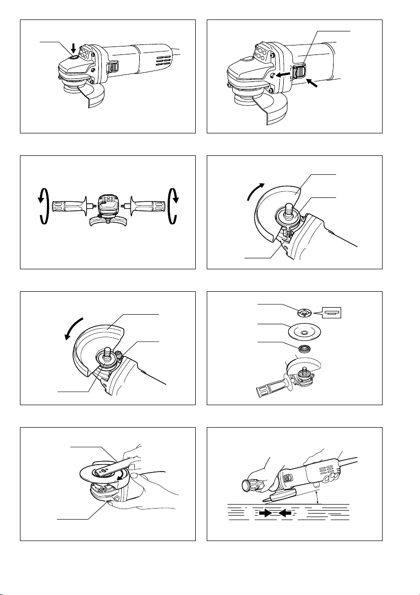
Shaft lock (Fig. 1)
CAUTION:
• Never actuate the shaft lock when the spindle is moving. The tool may be damaged.
Press the shaft lock to prevent spindle rotation when
installing or removing accessories.
Switch action (Fig. 2)
CAUTION:
• Before plugging in the tool, always check to see that
the slide switch actuates properly and returns to the
“OFF” position when the rear of the slide switch is
depressed.
To start the tool, slide the slide switch toward the “I (ON)”
position. For continuous operation, press the front of the
slide switch to lock it.
To stop the tool, press the rear of the slide switch, then
slide it toward the “O (OFF)” position.
ASSEMBLY
CAUTION:
• Always be sure that the tool is switched off and
unplugged before carrying out any work on the tool.
Installing side grip (handle) (Fig. 3)
CAUTION:
• Always be sure that the side grip is installed securely
before operation.
Screw the side grip securely on the position of the tool as
shown in the figure.
Installing or removing wheel guard (Fig. 4 & 5)
CAUTION:
• The wheel guard must be fitted on the tool so that the
closed side of the guard always points toward the operator.
Mount the wheel guard with the protrusion on the wheel
guard band aligned with the notch on the bearing box.
Then rotate the wheel guard around 180 degrees. Be
sure to tighten the screw securely.
To remove wheel guard, follow the installation procedure
in reverse.
Installing or removing depressed center grinding
wheel/Multi-disc
Mount the inner flange onto the spindle. Fit the wheel/
disc on the inner flange and screw the lock nut onto the
spindle. (Fig. 6)
To tighten the lock nut, press the shaft lock firmly so that
the spindle cannot revolve, then use the lock nut wrench
and securely tighten clockwise.
To remove the wheel, follow the installation procedure in
reverse. (Fig. 7)
WARNING:
• Only actuate the shaft lock when the spindle is not
moving.
OPERATION
WARNING:
• It should never be necessary to force the tool. The
weight of the tool applies adequate pressure. Forcing
and excessive pressure could cause dangerous wheel
breakage.
• ALWAYS replace wheel if tool is dropped while grinding.
• NEVER bang or hit grinding disc or wheel onto work.
• Avoid bouncing and snagging the wheel, especially
when working corners, sharp edges etc. This can
cause loss of control and kickback.
• NEVER use tool with wood cutting blades and other
sawblades. Such blades when used on a grinder frequently kick and cause loss of control leading to personal injury.
CAUTION:
• After operation, always switch off the tool and wait until
the wheel has come to a complete stop before putting
the tool down.
Grinding and sanding operation (Fig. 8)
ALWAYS hold the tool firmly with one hand on housing
and the other on the side handle. Turn the tool on and
then apply the wheel or disc to the workpiece.
In general, keep the edge of the wheel or disc at an angle
of about 15 degrees to the workpiece surface.
During the break-in period with a new wheel, do not work
the grinder in the B direction or it will cut into the workpiece. Once the edge of the wheel has been rounded off
by use, the wheel may be worked in both A and B direction.
MAINTENANCE
CAUTION:
• Always be sure that the tool is switched off and
unplugged before attempting to perform inspection or
maintenance.
The tool and its air vents have to be kept clean. Regularly
clean the tool’s air vents or whenever the vents start to
become obstructed. (Fig. 9)
To maintain product SAFETY and RELIABILITY, repairs,
any other maintenance or adjustment should be performed by Makita Authorized or Factory Service Centers,
always using Makita replacement parts.
6
Page 7

ACCESSORIES
CAUTION:
• These accessories or attachments are recommended
for use with your Makita tool specified in this manual.
The use of any other accessories or attachments might
present a risk of injury to persons. Only use accessory
or attachment for its stated purpose.
If you need any assistance for more details regarding
these accessories, ask your local Makita service center.
• Wheel guard (Wheel cover)
• Inner flange
• Depressed center wheels
• Lock nut (For depressed center wheel)
• Rubber pad
• Abrasive discs
• Lock nut (For abrasive disc)
• Lock nut wrench
• Wire cup brush
• Wire bevel brush 85
• Side grip
• Dust collecting wheel guard
7
Page 8

NEDERLANDS
Verklaring van algemene gegevens
1 Asblokkering
2 Schuifschakelaar
3 Beschermkap
4 Schroef
TECHNISCHE GEGEVENS
Model 9556NB 9557NB 9558NB
Diameter slijpschijf ........................................................ 100mm 115 mm 125mm
Asschroefdraad ............................................................ M10 M14 M14
Toerental onbelast/min. (min
Totale lengte ................................................................. 271 mm 271 mm 271 mm
Netto gewicht ................................................................1,6 kg 1,6 kg 1,6 kg
Veiligheidsklasse ........................................................... /II /II /II
-1
) ..................................... 11 000 11 000 11 000
5 Kussenblokkast
6 Borgmoer
7 Afbraamschijf/multi-schijf
8 Binnenflens
9 Borgmoersleutel
10 Asblokkering
11 Luchtuitlaatopening
12 Luchtinlaatopening
• In verband met ononderbroken research en ontwikkeling behouden wij ons het recht voor bovenstaande
technische gegevens te wijzigen zonder voorafgaande
kennisgeving.
• Opmerking: De technische gegevens kunnen van land
tot land verschillen.
Doeleinden van gebruik
Dit gereedschap is bedoeld voor het snijden, slijpen en
schuren van metaal- en steenmaterialen zonder gebruik
van water.
Stroomvoorziening
Het gereedschap mag alleen worden aangesloten op
een stroombron van hetzelfde voltage als aangegeven op
de naamplaat, en kan alleen op enkel-fase wisselstroom
worden gebruikt. Het gereedschap is dubbel-geïsoleerd
volgens de Europese standaard en kan derhalve ook op
een niet-geaard stopcontact worden aangesloten.
Veiligheidswenken
Voor uw veiligheid dient u de bijgevoegde Veiligheidsvoorschriften nauwkeurig op te volgen.
AANVULLENDE
VEILIGHEIDSVOORSCHRIFTEN VOOR HET
GEREEDSCHAP
1. Draag tijdens het werk altijd oog- en oorbescher-
ming. Draag ook andere beschermuitrusting
zoals een stofmasker, handschoenen, een helm
en een voorschoot.
2. Schakel het gereedschap uit en haal zijn nets-
noer uit het stopcontact alvorens enig werk aan
het gereedschap uit te voeren.
3. Houd de beschermkappen op hun plaats.
4. Gebruik uitsluitend schijven van de juiste
grootte en met een maximaal bedrijfstoerental
dat minstens even hoog is als het hoogste “No
Load Speed” (toerental onbelast) dat op de
naamplaat van het gereedschap is opgegeven.
Wanneer u schijven met een verzonken asgat
gebruikt, gebruik dan uitsluitend schijven die
met glasvezel zijn versterkt.
5. Controleer de schijf vóór elk gebruik zorgvuldig
op scheuren, barsten of beschadiging. Vervang
een gescheurd, gebarsten of beschadigd schijf
onmiddellijk.
6. Volg de instructies van de fabrikant voor het juist
monteren en gebruiken van de schijven zorgvuldig op. Behandel de schijven voorzichtig en berg
deze met zorg op.
7. Gebruik geen afzonderlijke verloopmoffen of
adapters om schuurschijven met een groot asgat
aan dit gereedschap aan te passen.
8. Gebruik uitsluitend flenzen die voor dit gereedschap zijn bestemd.
9. Pas op dat u de as, de flens (vooral het montagevlak) of de klembout niet beschadigt. Beschadiging van deze onderdelen kan leiden tot
schijfbreuk.
10. Voor gereedschap waarop schijven met een
geschroefd asgat dienen gemonteerd te worden,
moet u ervoor zorgen dat de schroefdraad in de
schijf lang genoeg zodat de as helemaal erin
gaat.
11. Laat het gereedschap tenminste 30 seconden
lang met het maximale onbelaste toerental
draaien op een veilige plaats alvorens het op een
werkstuk te gebruiken. Stop het gereedschap
onmiddellijk als er sprake is van trilling of
beving die het gevolg kunnen zijn van onjuiste
installatie of een slecht uitgebalanceerde schijf.
Controleer het gereedschap om de oorzaak van
het probleem te bepalen.
12. Zorg ervoor dat het werkstuk goed ondersteund
is.
13. Houd het gereedschap stevig vast.
14. Houd uw handen uit de buurt van draaiende
onderdelen.
15. Zorg ervoor dat schuurschijf het werkstuk niet
raakt voordat het gereedschap is ingeschakeld.
16. Voor slijpwerkzaamheden moet u het schijfoppervlak gebruiken dat daarvoor bestemd is.
17. Gebruik de doorslijpschijf niet voor zijdelings
slijpen.
18. Pas op voor rondvliegende vonken. Houd het
gereedschap zodanig vast dat er geen vonken
op uzelf, andere personen of ontvlambaar materiaal terecht kunnen komen.
19. Houd er rekening mee dat de schijf nog een tijdje
blijft draaien nadat het gereedschap is uitgeschakeld.
20. Raak het werkstuk niet aan onmiddellijk na het
werk; het werkstuk kan gloeiend heet zijn en
brandwonden veroorzaken.
17
Page 9

21. Plaats het gereedschap zodanig dat zijn netsnoer tijdens het gebruik altijd achter het gereedschap blijft.
22. Indien de werkplaats uiterst warm en vochtig is,
of erg verontreinigd is door geleidend stof,
gebruik dan een stroomonderbreker (30 mA) om
de veiligheid van de gebruiker te verzekeren.
23. Gebruik het gereedschap niet op materialen die
asbest bevatten.
24. Gebruik geen water of slijpolie.
25. Houd de ventilatieopeningen schoon wanneer u
in een stoffige omgeving werkt. Wanneer u stof
uit deze openingen wilt verwijderen, moet u
eerst de aansluiting van het gereedschap op het
stopcontact verbreken en oppassen dat u geen
inwendige onderdelen beschadigt (gebruik voor
het reinigen uitsluitend niet-metalen voorwerpen).
26. Wanneer u een afkortschijf gebruikt, dient u
altijd te werken met de stofvangbeschermkap
die door de plaatselijke overheid wordt voorgeschreven.
27. Afkortschijven mogen niet aan zijwaartse druk
worden blootgesteld.
BEWAAR DEZE VOORSCHRIFTEN.
BESCHRIJVING VAN DE FUNCTIES
LET OP:
• Zorg altijd dat het gereedschap is uitgeschakeld en zijn
stekker uit het stopcontact is verwijderd voordat u functies op het gereedschap afstelt of controleert.
Asblokkering (Fig. 1)
LET OP:
• Druk de asblokkering nooit in terwijl de as beweegt.
Hierdoor kan het gereedschap beschadigd raken.
Druk de asblokkering in om draaiing van de as te voorkomen wanneer u accessoires wilt installeren of verwijderen.
Werking van de schakelaar (Fig. 2)
LET OP:
• Voordat u het gereedschap op een stopcontact aan-
sluit, moet u altijd controleren of de schuifschakelaar
goed werkt en naar de “OFF” positie terugkeert wanneer het achterste gedeelte ervan wordt ingedrukt.
Schuif de schuifschakelaar naar de “I (AAN)” positie om
het gereedschap te starten. Voor continu gebruik drukt u
het voorste gedeelte van de schuifschakelaar in om hem
te vergrendelen.
Om het gereedschap te stoppen, druk het achterste
gedeelte van de schuifschakelaar in en schuif hem vervolgens naar de “O (UIT)” positie.
INEENZETTEN
LET OP:
• Zorg altijd dat het gereedschap is uitgeschakeld en zijn
stekker uit het stopcontact is verwijderd alvorens enig
werk aan het gereedschap uit te voeren.
Monteren van de zijhandgreep (handvat) (Fig. 3)
LET OP:
• Controleer altijd of de zijhandgreep stevig bevestigd is
alvorens met het werk te beginnen.
Schroef de zijhandgreep stevig vast op het gereedschap
op de plaats die is afgebeeld.
Installeren of verwijderen van de beschermkap
(Fig. 4 en 5)
LET OP:
• De beschermkap dient zodanig op het gereedschap te
worden gemonteerd dat de gesloten zijde ervan altijd
naar de gebruiker is gericht.
Monteer de beschermkap zodanig dat het uitsteeksel op
de beschermkapband overeenkomt met de inkeping in
de kussenblokkast. Draai daarna de beschermkap 180
graden rechtsom. Draai de schroef stevig vast.
Om de beschermkap te verwijderen, voert u deze procedure in omgekeerde volgorde uit.
Installeren of verwijderen van de afbraamschijf/
multi-schijf
Monteer de binnenflens op de as. Plaats de schijf/multischijf over de binnenflens en schroef de borgmoer vast
op de as. (Fig. 6)
Om de borgmoer vast te draaien, dient u stevig op de
asblokkering te drukken zodat de as niet kan draaien.
Draai vervolgens met de borgmoersleutel de borgmoer
stevig naar rechts vast.
Om de schijf te verwijderen, voert u deze procedure in
omgekeerde volgorde uit. (Fig. 7)
WAARSCHUWING:
• Druk de asblokkering alleen in wanneer de as niet
beweegt.
BEDIENING
WAARSCHUWING:
• U dient nooit kracht op het gereedschap uit te oefenen.
Het eigen gewicht van het gereedschap levert voldoende druk op. Overmatige kracht of druk kan schijfbreuk veroorzaken, hetgeen gevaarlijk is.
• Vervang ALTIJD de schijf indien het gereedschap tijdens het slijpen op de grond is gevallen.
• Bots of stoot de slijpschijf NOOIT tegen het werkstuk.
• Zorg dat de schijf niet terugkaatst of blijft hangen,
vooral bij het bewerken van hoeken, scherpe randen,
enz. Dit kan namelijk verlies van controle over het
gereedschap en terugslag veroorzaken.
• Gebruik het gereedschap NOOIT met houtzaagbladen
of andere zaagbladen. Bij gebruik op een slijpmachine
veroorzaken zaagbladen vaak terugslag en controleverlies, met persoonlijke verwonding als mogelijk
gevolg.
LET OP:
• Schakel na het gebruik het gereedschap uit en wacht
totdat de schijf volledig tot stilstand is gekomen alvorens het gereedschap neer te leggen.
18
Page 10

Slijpen en schuren (Fig. 8)
Houd het gereedschap ALTIJD goed vast met de ene
hand op het gereedschapshuis en de andere op de zijhandgreep. Schakel het gereedschap in en zet de slijpof schuurschijf op het werkstuk.
Houd normaal de rand van de slijp- of schuurschijf bij
een hoek van ongeveer 15 graden ten opzichte van het
werkstukoppervlak.
Bij gebruik van een nieuwe schijf mag u deze aanvankelijk niet in de richting B gebruiken, omdat de schijf anders
in het werkstuk zal snijden. Wanneer de rand van de
schijf door gebruik ronder geworden is, kunt u de schijf
zowel in richting A als in richting B gebruiken.
ONDERHOUD
LET OP:
• Zorg altijd dat het gereedschap is uitgeschakeld en zijn
stekker uit het stopcontact is verwijderd alvorens te
beginnen met inspectie of onderhoud.
Houd het gereedschap en zijn luchtopeningen altijd
schoon. Reinig de luchtopeningen van het gereedschap
regelmatig of telkens wanneer ze verstopt beginnen te
raken. (Fig. 9)
Om de VEILIGHEID en BETROUWBAARHEID van het
gereedschap te verzekeren, dienen alle reparaties,
onderhoudsbeurten of afstellingen te worden uitgevoerd
bij een erkend Makita Servicecentrum of Fabriekservicecentrum, en dit uitsluitend met gebruik van Makita vervangingsonderdelen.
ACCESSOIRES
LET OP:
• Deze accessoires of hulpstukken worden aanbevolen
voor gebruik met het Makita gereedschap dat in deze
gebruiksaanwijzing wordt beschreven. Het gebruik van
andere accessoires of hulpstukken kan gevaar voor
persoonlijke verwonding opleveren. Gebruik de accessoires of hulpstukken uitsluitend voor het gespecificeerde doel.
Wenst u meer informatie over deze accessoires, neem
dan contact op met het dichtstbijzijnde Makita servicecentrum.
• Beschermkap (Schijfdeksel)
• Binnenflens
• Afbraamschijven
• Borgmoer (voor afbraamschijf)
• Rubbersteunschijf
• Schuurschijven
• Borgmoer (voor schuurschijf)
• Borgmoersleutel
• Komdraadborstel
• Draadborstel 85
• Zijhandgreep
• Stofvangbeschermkap
19
 Loading...