

Page 1
T
ECHNICAL INFORMATION
Models No.
9556HN, 9557HN, 9558HN
PRODUCT
P 1/ 8
Description
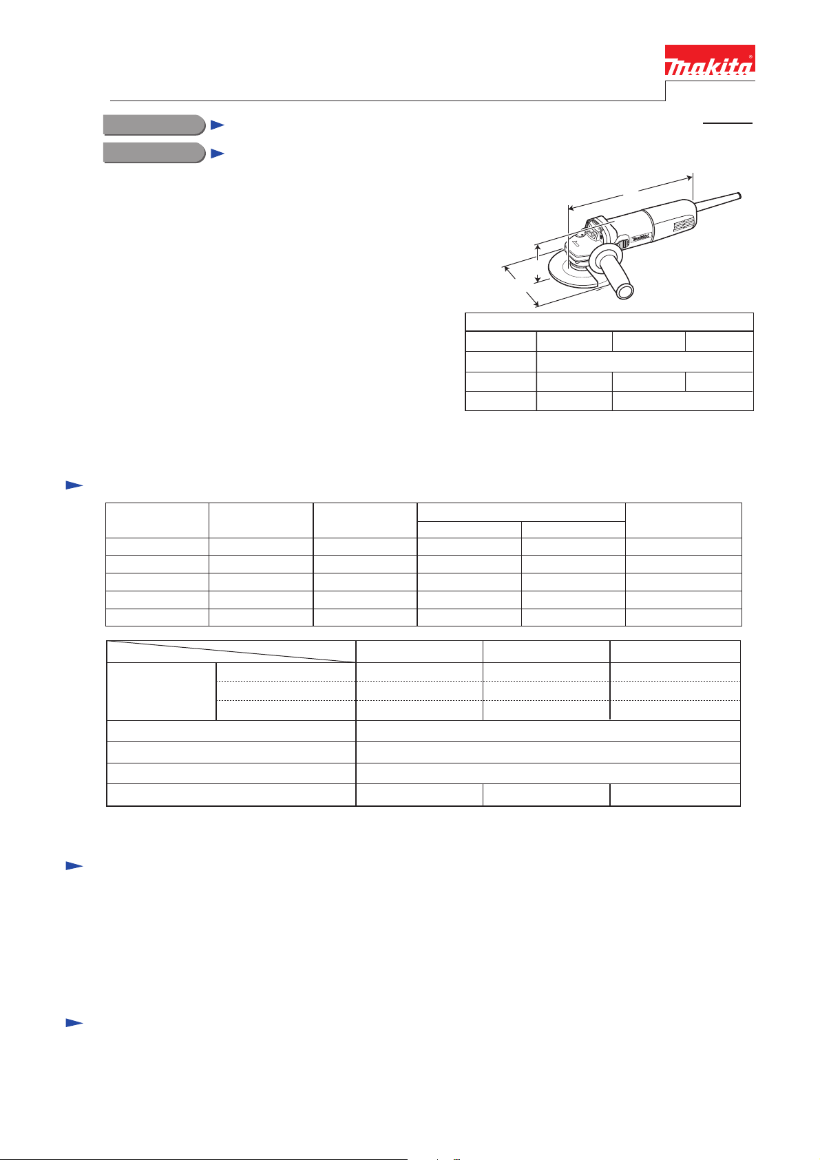
Angle Grinders 100mm (4"), 115mm (4-1/2"), 125mm (5")
CONCEPT AND MAIN APPLICATIONS
These angle grinders have been developed as sister models
of 9556NB series.
Features machined bevel gears more durable than sintered
bevel gears used for 9556NB series models.
9556HN is also available with plastic carrying case as
Model 9556HNK.
9557HN is also available with plastic carrying case or
steel carrying case as Model 9557HNK.
9558HN is also available with steel carrying case as
Model 9558HNK.
AC/DC switch is used for the tools for USA and other
North American countries.
Specification
Voltage (V) Cycle (Hz)
110
120
220
230
240
Current (A)
8.0
7.5
4.0
3.8
3.7
50/60
50/60
50/60
50/60
50/60
H
W
Dimensions: mm (")
Model No. 9556HN
Length (L)
Width (W)
Height (H)
Continuous Rating (W)
Input Output
840
840
840
840
840
118 (4-5/8)
97 (3-13/16)
500
500
500
500
500
L
9557HN
271 (10-5/8)
129 (5-1/8)
106 (4-3/16)
Max. Output (W)
1,000
1,000
1,000
1,000
1,000
9558HN
139 (5-1/2)
Specification
Depressed center wheel
Capacity: mm (")
Protection against electric shock Double insulation
Power supply cord: m (ft)
Net weight*2: kg (lbs)
*1 North America: 10,000
*2 Weight according to EPTA-Procedure 01/2003
Wire cup brush
Abrasive disc
Model No.
9556HN 9557HN 9558HN
100 (4) 115 (4-1/2) 125 (5)
75 (3) 90 (3-1/2) 90 (3-1/2)
100 (4) 115 (4-1/2) 125 (5)
11,000No load speed*1: min.-1 = rpm
Australia, New Zealand: 2.0 (6.6), Other countries: 2.5 (8.2)
1.9 (4.2) 2.1 (4.6)2.0 (4.4)
Standard equipment
9556HN
Depressed center wheel 100-36 .... 1
Lock nut wrench 20 ...................... 1
Grip 36 complete .......................... 1
Plastic or steel carrying case ......... 1 (for 9556HNK, 9557HNK, 9558HNK only)
Note: The standard equipment for the tool shown above may vary by country.
9557HN
Depressed center wheel 115-36 .... 1
Lock nut wrench 28 ...................... 1
Grip 36 complete .......................... 1
9558HN
Depressed center wheel 125-36 .... 1
Lock nut wrench 35 ...................... 1
Grip 36 complete .......................... 1
Optional accessories
Wheel covers, Depressed center wheels, Abrasive discs, Rubber pads (for abrasive discs), Sanding lock nuts,
Cut-off wheels, Super flanges (for 9557HN, 9558HN only), Wire cup brushes, Wire bevel brush (for 9556HN only),
Dust collecting wheel guards
Page 2
P 2/ 8
Repair
CAUTION: Disconnect the machine and remove the wheel for safety before repair/maintenance!
[1] NECESSARY REPAIRING TOOLS
Code No. Description
1R028 Bearing Setting Pipe
1R045 Gear Extractor (large)
1R346 Center Attachment for 1R045
1R269 Bearing Extractor Removing Ball bearings
1R291 Retaining Ring S and R Pliers Removing Retaining ring S-12 and R-32
1R343 Retaining Ring Setting Jig
1R----- Bearing Setting Plate (of proper size) Assembling Ball bearing 629LLB and Armature to Gear housing cover
Installing Retaining ring S-12
Removing Spindle from Bearing box
Removing Spindle from Bearing box (for modular use with 1R045)
Installing Retaining ring S-12
Use for
[2] LUBRICATION AND SEALING
Put 7g of Makita Grease N. No.1 into the gear room of Gear housing.
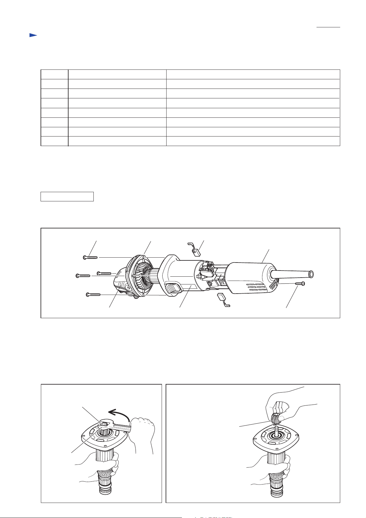
[3] DISASSEMBLY/ASSEMBLY
[3] -1. Armature and Spiral Bevel Gear 10
DISASSEMBLING
1) Remove 4x18 Tapping screw and separate Rear cover from Motor housing. Then remove Carbon brushes. (Fig. 1)
2) Unscrew four 4x30 Tapping screws and remove the assembled unit of Gear housing and Armature. (Fig. 1)
Fig. 1
Tapping screw 4x30 (4 pcs)
Gear housing cover
Carbon brush (2 pcs)
Rear cover
Gear housing
3) Pull off the assembled unit of Armature and Gear housing cover from Gear housing.
4) Grip Armature securely by gloved hand, then remove Hex nut M6 by turning counterclockwise with wrench 10. (Fig. 2)
5) Remove Spiral bevel gear 10 by gloved hand. (Fig. 3)
If the gear cannot be removed by hand, do the following steps;
1. Spray some lubricant to the contact portion of the gear and Armature shaft.
2. Wrap the gear with wasted cloth for protection of the gear threads, then turn the gear using water pump pliers.
6) Remove Armature from Gear housing cover with Gear Extractor, large (No.1R045).
Fig. 2 Fig. 3
Hex nut M6
Wrench 10
Motor housing
Spiral bevel gear 10
Tapping screw 4x18
Page 3
Repair
[3] -1. Armature and Small Spiral Bevel Gear (cont.)
ASSEMBLING
Do the reverse of the disassembling steps.
Note: Use arbor press and Bearing Setting Plate (of proper size ) when fitting Ball bearing 629LLB
in Gear housing cover. (Fig. 4)
Important: Assemble Gear housing to Motor housing so that Switch lever can be operated with right thumb
as illustrated in Fig. 5.
Fig. 4 Fig. 5
P 3/ 8
Ball bearing 629LLB
Gear housing cover
Switch lever
Spindle
Bearing setting plate
(of proper size)
[View from rear cover side]
Power supply cord
Rear cover
Tapping screw
4x18
(Wheel)
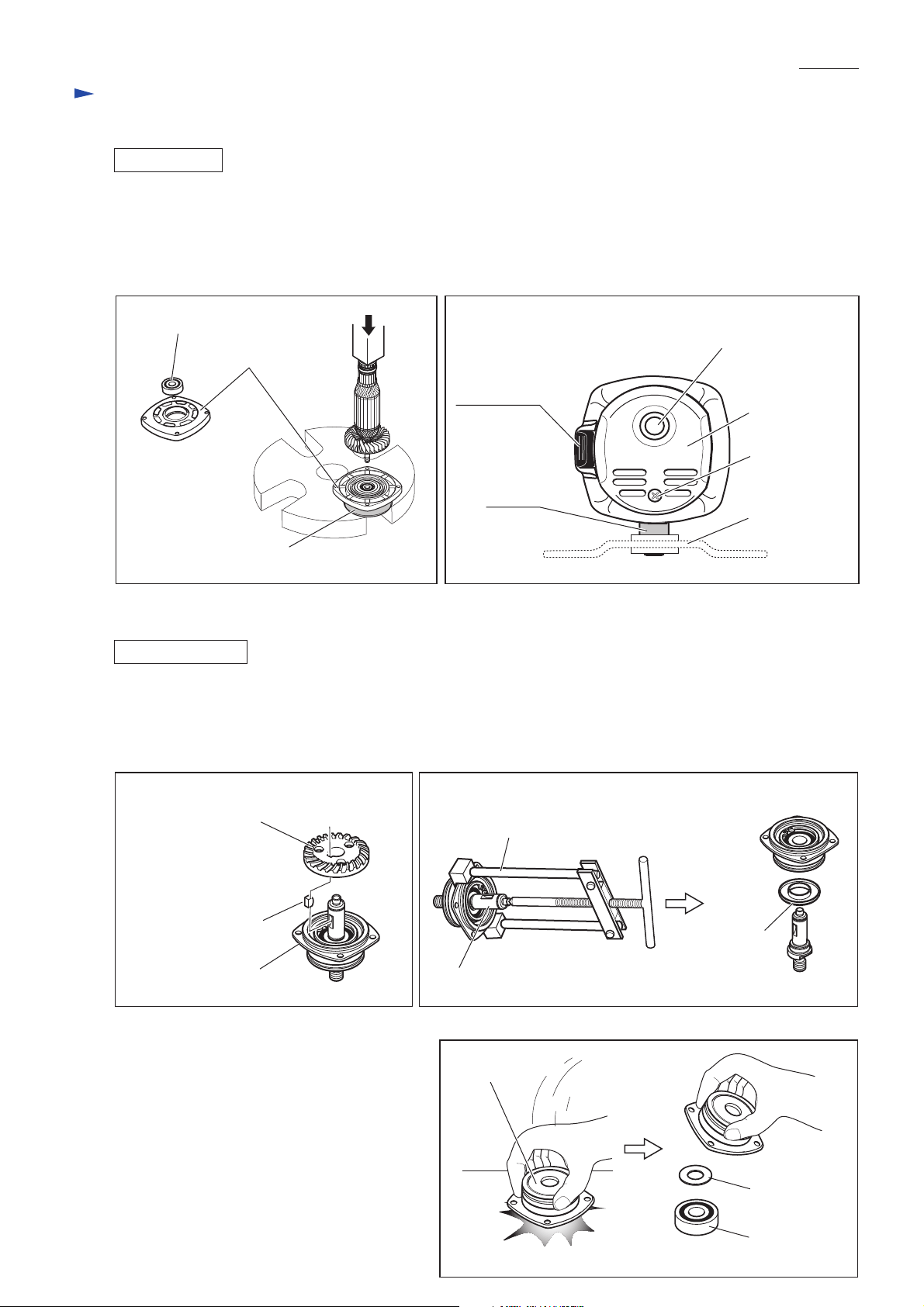
[3] -2. Spiral Bevel Gear 37 and Ball Bearing 6201DDW
DISASSEMBLING
1) Remove Bearing box from Gear housing by unscrewing four M4x14 Pan head screws.
2) Remove Retaining ring S-12 and Wave washer 12 from Spindle with Retaining Ring S and R Pliers (No.1R291).
3) Spiral bevel gear 37 can now be removed by hand. Then remove Woodruff key 4. (Fig. 6)
4) Remove Spindle using Gear Extractor, large (No.1R045). Labyrinth ring can now be removed. (Fig. 7)
Fig. 6 Fig. 7
Spiral bevel gear 37
Woodruff key 4
Bearing box
5) Remove Retaining ring R-32 from Bearing box
with Retaining Ring S and R Pliers (No.1R291).
6) By striking Bearing box against the surface of
a work bench, Ball bearing 6201DDW and Flat
washer 12 can be removed from Bearing box
as illustrated in Fig. 8.
If it is difficult to remove the ball bearing,
remove using arbor press.
Gear Extractor, large (No.1R045)
Labyrinth
ring
Spindle
Fig. 8
Bearing box
Flat washer 12
Ball bearing
6201DDW
Page 4

P 4/ 8
Repair
[3] -2. Spiral Bevel Gear 37 and Ball Bearing 6201DDW (cont.)
ASSEMBLING
Do the reverse of the disassembling steps.
Important: Do not to forget to install Labyrinth ring because it is an important part that prevents dust from entering
into Bearing box. (Fig. 9)
How to fit Retaining ring S-12 in place
See Fig. 10.
After installing Spiral bevel gear 37 and Wave washer 12 on Spindle;
1) Put Retaining ring S-12 on Retaining Ring Setting Jig (No.1R343) from the tapered end of the jig.
2) Put the jig onto Spindle, then put Bearing Setting Pipe 20-12.2 (No.1R028) over the jig.
3) Using arbor press, press down the pipe till the retaining ring is securely fitted in place on Spindle with a snap.
Fig. 9 Fig. 10
Labyrinth ring
Bearing box
Spindle
Retaining
ring S-12
No.1R343
[3] -3. Disassembling/Assembling Shaft Lock Mechanism
DISASSEMBLING
1) Remove Bearing box from Gear housing.
2) Pull off Shoulder pin 4 with pliers while pushing Pin cap with
finger. (Fig. 11)
Note: Do not pull off Shoulder pin 4 without holding Pin cap
because Compression spring 8 would sling Pin cap.
ASSEMBLING
Push Shoulder pin 4 through Gear housing and Compression spring 8
into Pin cap.
Note: Do not reuse removed Pin cap because removal of Shoulder
pin 4 damages the inside surface of Pin cap, producing plastic
dust. Therefore, be sure to use a new Pin cap for replacement
and to remove all the plastic dust on Shoulder pin 4.
Fig. 11
Shoulder pin 4
Compression
spring 8
Pin cap
No.1R028
Retaining
ring S-12
Gear housing
[3] -4. Tightening Tapping Screws That Fasten the Field
Tighten the two tapping screws that fasten Baffle plate and Field to the recommended torque of 1.1 - 1.3 Nm.
Page 5

Circuit diagram
Color index of lead wires' sheath
Black
Red
Clear
Brush holder A
P 5/ 8
Earth terminal (Ground terminal)
on the lead wire of Noise suppressor
Noise suppressor*
Brush holder B
Field
Brush holder A
Power supply
cord
Switch
*Some countries do not use noise suppressor
Brush holder B
Page 6

Wiring diagram
[1] Connecting Lead Wires of Power Supply Cord with Switch
Connect the lead wires with Switch as illustrated in Fig. 12.
Fig. 12
[When Spacer is used] [When Spacer is not used]
Power supply cord
Switch button
Switch
Spacer
P 6/ 8
[2] Wiring of Field Lead Wires in the Rear of Motor Housing
[2] -1. Rear End
Route Field lead wires as illustrated in Figs. 13 - 16.
Fig. 13
[Lead Wires of Field]
Lead wire (black)
Earth terminal on the lead wire (clear)
of Noise suppressor* has to be connected
to this portion.
Field
Lead wire (white)
Switch lever
[Motor Housing with Field]
(view from Rear cover side)
Connect to Brush holder A.
Brush holder A
Lead wire
(black)
Lead wire (white)
Lead wire (black)
Connect to Brush holder B.
Connect to
Switch terminals.
Brush holder B
Spindle
*Some countries do not use noise suppressor.
Page 7

Wiring diagram
[2] Wiring of Field Lead Wires in the Rear of Motor Housing (cont.)
[2] -2. Right Side and Bottom
Fig. 14
Right side view
P 7/ 8
Motor housing
Boss A
Route the lead wire of Power supply cord to
Switch terminal No.2 so that it runs around the boss A.
Boss A Boss A
Noise suppressor*
Switch
Motor housing
Boss A
Bottom view
Switch
Field lead wires
(white)
Motor housing,
viewed from right side
Field lead wire
(black)
Make sure that Field lead wires
are tight in Motor housing.
*Some countries do not use noise suppressor.
Motor housing,
viewed from bottom
Page 8

Wiring diagram
[2] Wiring of Field Lead Wires in the Rear of Motor Housing (cont.)
[2] -3. Left Side
Fig. 15
Earth terminal on the lead wire (clear)
of Noise suppressor* has to be connected
to this portion.
P 8/ 8
Left side view
Make sure that Field lead wires
are tight in Motor housing.
*Some countries do not use noise suppressor.
[2] -4. Top
Fig. 16
Top view
Noise suppressor*
Earth terminal on
the lead wire (clear)
of Noise suppressor*
has to be connected
to this portion.
*Some countries do not use noise suppressor.
**Some countries do not use sensormatic tag.
Noise suppressor*
Sensor-matic tag
(anti-theft tag)
Put Sensor-matic tag** in this space.
 Loading...