

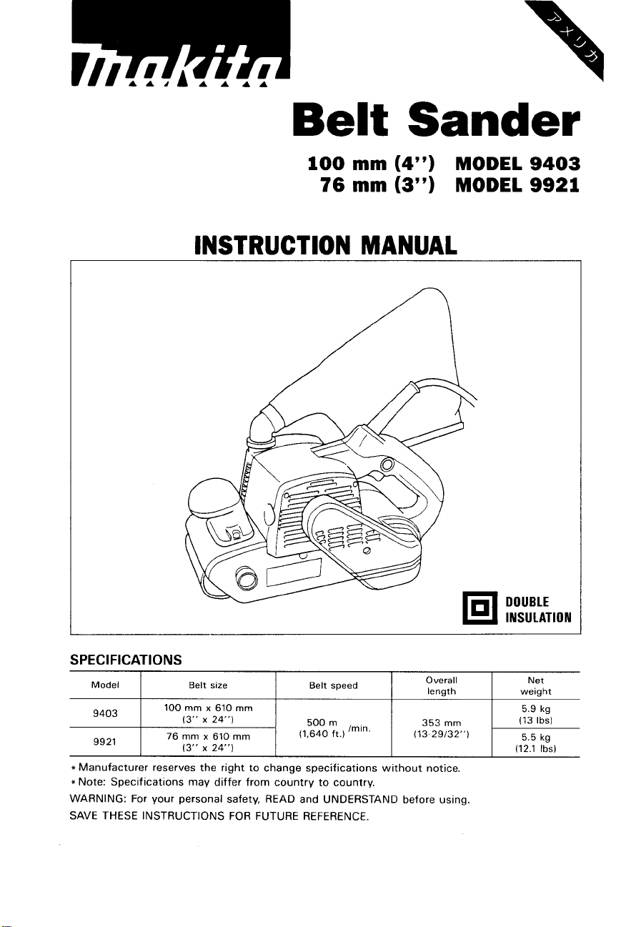
Belt
Sander
100
76
mm
mm
(4")
(3")
MODEL
MODEL
INSTRUCTION MANUAL
9403
9921
SPEC I Fl
*
*
WARNING: For your personal safety, READ and UNDERSTAND before using.
SAVE THESE INSTRUCTIONS FOR FUTURE REFERENCE.
CAT1 0 N S
Model
----
Y4UJ
nniq
JJL
Manufacturer reserves the right to change specifications without notice.
Note: Specifications may differ from country to country.
I
I
I
I
Belt size Belt speed
100
mm x 610 mm
(3"
x
24")
76 mm x 610"
(3"
x
24")
I I
(1,640
I
500m
ft.)
"In'
Overall Net
length weight
353 mm (13
(13-29132")
I
I I
DOUBLE
INS
U
I
5.9
(12.1
L
Ibsl
AT
ko
lbsl
ION
GENERAL
SAFETY
RULES
(For
WARNING! Read and understand
to follow
shock,
all
instructions listed below, may result
fire and/or serious personal injury.
SAVE THESE INSTRUCTIONS
.
READ ALL INSTRUCTIONS.
1.
Keep your work area clean and well
accidents.
2.
Do not operate power tools
of flammable liquids, gases, or dust. Power tools create sparks which may
ignite the dust or fumes.
3.
Keep bystanders, children, and visitors away while operating a power tool.
Distractions can cause you to loose control.
4.
Double Insulated tools are equipped with a polarized plug (one blade is wider
than the other.) This plug will fit
fit
plug does not
contact a qualified electrician to install a polarized outlet. Do not change
the plug in any way. Double insulation
wire grounded power cord and grounded power supply system.
5.
Avoid body contact with grounded surfaces such as pipes, radiators, ranges
and refrigerators. There is an increased risk of electric shock if your body is
grounded.
6.
Don't expose power tools to rain or wet conditions. Water entering a power
will
tool
7.
Do
from an outlet. Keep cord away from heat, oil, sharp edges or moving parts.
Replace damaged cords immediately. Damaged cords increase the risk of
electric shock.
8.
When operating a power tool outside, use an outdoor extension cord marked
"W-A'
of electric shock.
9.
Stay alert, watch what you are doing and use common sense when operating
a power tool.
alcohol, or medication.
may result in serious personal injury.
IO.
Dress properly.
your hair, clothing, and gloves away from moving parts. Loose clothes, jewelry
or long hair can be caught in moving parts.
increase the risk of electric shock.
not abuse the cord. Never use the cord to carry the tools or pull the plug
or
"W."
fully
These cords are rated for outdoor use and reduce the risk
Do
not use tool while tired or under the influence of drugs,
Do
not wear loose clothing or jewelry. Contain long hair. Keep
in
explosive atmospheres, such as in the presence
in
the outlet, reverse the plug.
A
moment of inattention while operating power tools
All
Tools)
all
instructions.
in
lit.
Cluttered benches and dark areas invite
in
a polarized outlet only one way.
If
it
still does not
I3
eliminates the need for the three
Failure
electric
If
the
fit,
2

11.
Avoid accidental starting. Be sure switch is off before plugging
tools
with
your finger on the switch or
on invites accidents.
12.
Remove adjusting keys or switches before turning the tool on. A wrench or
a key that is left attached to a rotating part
injury.
13.
Do not overreach. Keep proper footing and balance at all times. Proper footing
and balance enables better control of the tool
14.
Use safety equipment. Always wear eye protection. Dust mask, non-skid
safety shoes, hard hat, or hearing protection must be used for appropriate
conditions.
15. Use clamps or other practical way to secure and support the workpiece to
a stable platform. Holding the work by hand or against your body is unstable
and may lead to
16.
Do not force tool. Use the correct tool for your application. The correct tool
will do the job better and safer at the rate for which
17.
Do not use tool if switch does not turn
be controlled
18.
Disconnect the plug from the power source before making any adjustments,
changing accessories, or storing the tool. Such preventive safety measures
reduce the risk of starting the tool accidentally.
19.
Store idle tools out of reach of children and other untrained persons. Tools
are dangerous
20.
Maintain tools with care. Keep cutting tools sharp and clean. Properly
maintained tools,
to control.
21.
Check for misalignment or binding of moving parts, breakage of parts, and
any other condition that may affect the tools operation. If damaged, have
the tool serviced before using. Many accidents are caused by poorly maintained tools.
22.
Use only accessories that are recommended by the manufacturer for your
model. Accessories that may be suitable for one tool, may become hazardous
when used on another tool.
23.
Tool
service must be performed only by qualified repair personnel. Service
or maintenance performed by unqualified personnel could result
injury.
24.
When servicing a tool, use only identical replacement parts. Follow instruc-
in
tions
or failure
or injury.
the Maintenance section of this manual. Use of unauthorized parts
to
loss
of control.
with
the switch is dangerous and must be repaired.
in
the hands of untrained users.
with
sharp cutting edges are less likely to bind and are easier
follow Maintenance Instructions may create a risk of electric shock
plugging
in
tools that have the switch
of
the tool may result
in
unexpected situations.
it
is designed.
it
on or off. Any tool that cannot
in.
Carrying
in
personal
in
a
risk
of
3

Specific Safety Rules
1.
Hold tools by insulated gripping surfaces when performing an operation where
the cutting tool may contact hidden wiring or its own cord. Contact
"live" wire
operator.
2.
Hold the tool firmly with both hands.
3.
Make sure the belt is not contacting the workpiece before the switch is
turned on.
4.
Keep hands away from rotating parts.
5.
Do
not leave the tool running. Operate the tool only when hand-held.
6.
This tool has not been waterproofed,
surface.
will
make exposed metal parts
of
the tool "live" and shock the
so
do not use water on the workpiece
with
a
SAVE
THESE INSTRUCTIONS.
4
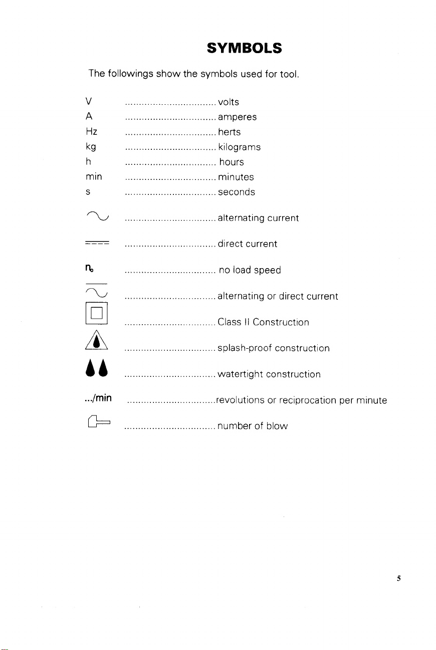
SYMBOLS
The followings show the symbols used for tool.
...............
.................................
.................................
........................
............................
.................................
...........................
.................................
?J
Dl
A
AA
.................................
.................................
.................................
.................................
...............
.................
volts
amperes
herts
kilograms
hours
seconds
alternating current
direct current
no
load
speed
alternating or direct current
Class
II
Construction
splash-proof construction
watertight construction
.../
min
G=l
................................
.................................
revolutions or reciprocation per minute
number
of
blow
5

the belt.
the orig
itself.
removing abrasive belt
sure that the tool is switched off and unplugged before installing or removing
all the way out and install the
rollers, then return the lever to
ial
position
Lever
Adjustir
While th
knob to
6
belt tracking
selt is running, use the adjustirlg
I
iter the belt tracking.
1
I
Adjusting
knob

the
firm11
comi
Dust
bag
t
bag, push
q
s
far
as it will go to prevent
off during operation.
best results, empty the dust bag
becomes about half full, tapping it
3
remove
action
it
onto the dust spout
as
much dust as possible.
it
from
\:'is
"""
IN
plugging in the tool, always check to see that the switch trigger actuates properly
turns to the "OFF" position when released
01
should not be in contact with the workpiece surface when you turn the tool on
Otherwise a poor sanding finish or damage of the belt may result
t
the tool, simply pull the trigger.
!
the trigger to stop. For continuous
in, pull the trigger and then push in
:
button. To stop the tool from the
>osition, pull the trigger fully, then
it.
7

Sanding operation
Hold the tool firmly with both hands. Turn the tool
on
and wait until it attains full speed.
Then gently place the tool on the workpiece surface. Keep the belt flush with the workpiece at all times and move the tool back and forth. Never force the
tool applies adequate pressure. Excessive pressure may cause stalling, overheating of the
.
motor, burning of the workpiece and possible kickback.
Connecting to Makita vacuum cleaner or dust collector
tool.
The weight of the
Cleaner sanding operations can be performed by connecting the belt sander to Makita
vacuum cleaner or dust collector.
When connecting to Makita vacuum cleaner, an optional hose 28
or
joint 25 is necessary. See the figure below.
mm
(1-1/8") in inner dia.
When connecting to Makita dust collector (Model 420.9, the optional hose or joint is not
necessary. You can connect the belt sander directly to the hose of the dust collector.
Hose
28
mm
(1-1/8")
Makita vacuum cleaner
Hose
for
vacuum cleaner
in
inner dia
Carbon plate
(Optional
Accessories)
For greater sanding efficiency and to help
the belt run cooler, install an optional
carbon plate on the steel plate when sanding hardwood or steel.
8
An

MAINTENANCE
CAUTION:
is
Always be sure that the tool
or
inspection
Remove and check the carbon brushes
regularly. Replace when they wear down to
the limit mark. Keep the carbon brushes
clean and free to slip in the holders. Both
carbon brushes should be replaced at the
same time. Use only identical carbon
brushes.
a
Use
holder caps. Take out the worn carbon
brushes, insert the new ones and secure
the brush holder caps.
maintenance.
screwdriver to remove the brush
switched
off
and unplugged before attempting
L
Limit
mark
to
perform
To maintain product SAFETY and RELIABILITY, repairs, any other maintenance or adjustment should be performed by Makita Authorized or Factory Service Centers, always using
Makita replacement parts.
9

ACCESSORIES
CAUTION
These accessories or attachments are recommended for use with your Makita tool specified in this
manual The use
The accessories or attachments should be used only in the proper and intended manner
of
any other accessories or attachments might present a risk of injury
to
persons
*Abrasive belts
For Model
9921
9403
76x610
I3
100 x 610
1
Per Pkg
Part
No
74231
2-8B
742312-8C
742312.80
794237-0-2
794237-C-2
794237-D-2
794237-E-2
742320-3
#60 742321-1
#80
I
742322-9
742323-7
742324-5
794133-F-2
-
Carbon plate
Part
No.
Dust bag
Part
No.
10

100
mm
BELT
Model
5
(4")
SANDER
9403
Nav.-12-'98
US
55
Note: The switch and other part configurations
may differ from country to country.
11

MODEL 9403
A&
DESCRIPTION
DESCRIPTION
Nor-12--'98
US
MACHINE
~
10
11
12
13
14
15
16
17
18
19
20
21
22
23
24
25
26
27
28
29
30
31
32
33
34
35
~
Note
1
2
3
4
5
6
7
8
9
The switch
Tapping
4
1
Handle Cover
I
Cord
Cord Guard
1
1
Switch
1
Motor Housing Complete
1
Tapping
1
Belt
Cover
1
Pulley
2
Brush Holder
2
Carbon Brush
1
Tapping
2
Tappinq
Strain
1
2
Tapping
1
Dust
Nozzle
1
0
Ring 28
2
Tapping
1
Tapping
1
Makita
1
Tapping
1
oust
Collector Cover
1
separator
1
Pan
Head
1
Fan
80
2
Tapping
1
Dust Collector Bracket
1
Ball Bearing 60OODDW
1
Fan
84
1
ARMATURE ASSEMBLY
IWiIh Item 28
1
Baffle
1
lnsulal
1
Ball
Bearing 6000DDW
1
Wave
FIELD
and other
Washer 18
ASSEMBLY
1
Screw
4x1 8
Screw
CT 4x16
10-
24
1
Cap
Screw
4x18
Screw
5x45
Rei
ef
Screw
4x18
Screw
4x45
Screw
4x18
Mark
Screw
Bind CT 4x40
Screw
M5x12
Screw
4x18
29
32 & 331
Plate
on
Washer
pdr:
spt~c8f~cations may differ from country to
MACHINE
__
36
37
38
39
40
41
42
43
44
45
46
47
48
49
50
51
52
53
54
55
56
57
58
59
60
61
62
63
64
65
86
67
68
69
70
-
country
1
Synchro
1
Hex NutM10
1
Pulley
3
Tapping
I
Gear
1
Helical
1
Frame Complete
4
Tapping
1
Edge Slider Complete
Ball Bearing 6001DDW
1
1
Driving
Hex Nut M12-19
1
2
Tapping
1
Safety
Tension
1
Compression Spring
1
1
Tension
1
support
1
Tension
1
Cup Washer 12
Tension
1
1
Cup Washer 12
1
Retaining Ring
3
Pan
1
Strap Washer
1
Steel
1
Front
2
Tapping
Helical
1
I
Ball
1
Pan
1
Name
1
Compression Spring 16
1
Flat
Screw
1
-
Bell
11 -55
Screw
Cover
Gear
Screw
Roller
Screw
cover
Roller
Spring
P,"
Roller
Roller
Head
Screw
Plate
Complete
Grip
Screw
Gear 12
Bearing
62OOLLE
Head
Screw
Plate
Washer 16
M6x25
6
CT 4x16
43
Complete
4x18
Bind CT 4x1
Arm
4
Shaft
Complete
S
12
M4x12
CT 4x16
M5x12
2
12
12

76
mm
BELT
Model
5
(3")
SANDER
9921
Nav-l2-'98
US
55
Note: The switch and other part configurations
may differ from country to country.
13

MODEL
'LLM
9921
AtD
DESCRIPTION
'LLM
AtD
DESCRIPTION
Nov.-l2--'98
US
MACHINE
1 4 Tapping
2 1 Handle Cover
3
1 Cord
4 1 Cord Guard
5
1
6
1 Motor Housing Complete
7
1 Tapping
8
1
9 1 Pulley 10- 24 1
10
2
2
11
12
1 Tapping
13
2
14 1 Strain
15
2
16
1 Dust
17
1
18
2
19 1 Tapping
20
1
1
21
22
1
23
1 Separator
24 1 Pan
25
1
26
2
27 1
28
1
29 1
30
1 ARMATURE ASSEMBLY
31 1
32 1
33
1
34 1 Wave
35
1
Screw
Switch
Screw
Belt
cover
Brush Holder Cap
Carbon Brush
Screw
Tapping
Screw
Relief
Tapping
Screw
Nozzle
0
Ring 28
Tapping
Screw
Screw
Makita Mark
Tapping
Screw
Dust
Collector
Head Screw
Fan
80
Tapping
Screw
Dust
Collector
Ball
Bearing
Fan
84
IWith Item
Baffle
Plate
ln~ulation
Washer
Ball
Bearing
Washer
FIELD ASSEMBLY
4x18
CT 4x16
4x18
5x45
4x18
4x45
4x18
CT 4x16
cover
4x18
Bracket
6000DDW
28
29 32
6000DDW
18
M5x12
WE
36 1
37 1
38 1
39
40 1
41 1
42 1
43 4
44 1
45 1
46 1
47 1
48
49 1
50
51
52 1
53
54 1
55
56
57 1
58 1
59
60
61 1
62
63
64 1
65
&
331
66
67
68 1
69
70
Synchro
Hex
NufM10
Pulley 11
3
Tapping
Gear
Cover
Helical
Frame Complete
Tapping
Edge Slider Complete
Ball
Bearing
Driving
Hex
Nut M12-19
Tapping Screw
2
Safety cover
Tension Roller
1
Compression Spring 12
1
Tension Spring 4
1
SLJpport
Tension
1
Cup Washer 12
Tension
1
Cup
Washer 12
Retaining Ring S-12
2
Pan
Head
Strap Wesher
1
Steel
Plate Complete
Front Grip
1
Tapping
2
Helical
1
Bell
Bearing
Pan
Head
1
Name
1
1
1
Plate
Compression Spring 16
Flat Washer 16
Screw
Belt
-55
Screw
Gear
Screw
Roller
P,"
Roller
Roller
Screw
Screw
Gear
Screw
M6x25
6
CT
43
Complete
4x18
6001DDW
Bind
Arm
Shaft
Complete
M4x12
CT
12
6200LLB
M5x12
4x16
CT 4x12
4x16
14


. . -. . . . . _._
P
MAKmA
Every Makita tool is thoroughly inspected and tested before leaving the factory.
be free of defects from worbnanship and materials for the period of ONE YEAR from the date of
original purchase. Should any trouble develop during this one-year period, return the COMPLETE
tool, freight prepaid,
the trouble is caused by defective workmanship or material, Makita will repair (or at our option,
replace) without charge.
This Warranty does not apply where:
0
repairs have been made or attempted by others:
0
repairs are required because of normal wear and tear:
0
The tool has been abused, misused or improperly maintained;
0
alterations have been made to the tool.
IN NO EVENT SHALL MAKITA BE LIABLE FOR ANY INDIRECT. INCIDENTAL OR CONSEQUENTIAL DAMAGES FROM THE SALE OR USE OF THE PRODUCT. THIS DISCLAIMER
APPLIES BOTH DURING AND AFTER THE TERM OF THIS WARRANTY.
MAKITA DISCLAIMS LIABILITY FOR ANY IMPLIED WARRANTIES, INCLUDING IMPLIED
WARRANTIES OF “MERCHANTABILITY” AND “FITNESS FOR A SPECIFIC PURPOSE,”
AFTER THE ONE-YEAR TERM OF THIS WARRANTY.
This
Warranty gives you specific legal rights, and you may also have other rights which vary from
state to state. Some states do not allow the exclusion or Limitation of incidental or consequential
damages,
so
limitation on how long an implied warranty lasts,
the above limitation or exclusion may not apply to you. Some states
LIMITED
ONE
YEAR
WARRANTY
Warranty Policy
It
is warranted
to
one of Makita’s Factory or Authorized Service Centers. If inspection shows
so
the above limitation may not apply to you.
do
to
not allow
Makita Corporation
3-11
-8, Sumiyoshi-cho,
Anjo, Aichi 446-8502 Japan
8841 89
-
062
PRINTED
1998-11
IN
JAPAN
-N
 Loading...