

Page 1
INSTRUCTION MANUAL
MANUEL D'INSTRUCTION
MANUAL DE INSTRUCCIONES
Electronic Sander Polisher
Ponceuse-polisseuse électronique
Lijadora Pulidora
9227C
9227CY
003430
WARNING:
For your personal safety, READ and UNDERSTAND before using.
SAVE THESE INSTRUCTIONS FOR FUTURE REFERENCE.
AVERTISSEMENT:
Pour votre propre sécurité, prière de lire attentivement avant l’utilisation.
GARDER CES INSTRUCTIONS POUR RÉFÉRENCE ULTÉRIEURE.
ADVERTENCIA:
Para su seguridad personal, LEA DETENIDAMENTE este manual antes de usar la herramienta.
GUARDE ESTAS INSTRUCCIONES PARA FUTURA REFERENCIA.
Page 2

ENGLISH
SPECIFICATIONS
Model 9227C/9227CY
Max capacities
Spindle thread 5/8”
No load speed (RPM) 0 - 3,000/min.
Overall length 470 mm (18-1/2”)
Net weight 3.0 kg (6.6 lbs)
• Due to our continuing programme of research and development, the specifications herein are subject to change
without notice.
• Note: Specifications may differ from country to country.
Wool pad 180 mm (7”)
Abrasive disc 180 mm (7”)
GENERAL SAFETY RULES
USA001-3
(For All Tools)
WARNING:
Read and understand all instructions.
Failure to follow all instructions listed below,
may result in electric shock, fire and/or serious personal injury.
SAVE THESE INSTRUCTIONS
Work Area
1. Keep your work area clean and well lit. Cluttered
benches and dark areas invite accidents.
2. Do not operate power tools in explosive atmo-
spheres, such as in the presence of flammable
liquids, gases, or dust. Power tools create sparks
which may ignite the dust or fumes.
3. Keep bystanders, children, and visitors away
while operating a power tool. Distractions can
cause you to lose control.
Electrical Safety
4. Grounded tools must be plugged into an outlet
properly installed and grounded in accordance
with all codes and ordinances. Never remove the
grounding prong or modify the plug in any way.
Do not use any adaptor plugs. Check with a qualified electrician if you are in doubt as to whether
the outlet is properly grounded. If the tools should
electrically malfunction or break down, grounding
provides a low resistance path to carry electricity
away from the user.
5. Avoid body contact with grounded surfaces
such as pipes, radiators, ranges and refrigera-
tors. There is an increased risk of electric shock if
your body is grounded.
6. Do not expose power tools to rain or wet conditions. Water entering a power tool will increase the
risk of electric shock.
7. Do not abuse the cord. Never use the cord to
carry the tools or pull the plug from an outlet.
Keep cord away from heat, oil, sharp edges or
moving parts. Replace damaged cords immediately. Damaged cords increase the risk of electric
shock.
8. When operating a power tool outside, use an
outdoor extension cord marked “W-A” or “W”.
These cords are rated for outdoor use and reduce
the risk of electric shock.
Personal Safety
9. Stay alert, watch what you are doing and use
common sense when operating a power tool. Do
not use tool while tired or under the influence of
drugs, alcohol, or medication. A moment of inat-
tention while operating power tools may result in
serious personal injury.
10. Dress properly. Do not wear loose clothing or
jewelry. Contain long hair. Keep your hair, clothing, and gloves away from moving parts. Loose
clothes, jewelry, or long hair can be caught in moving parts.
11. Avoid accidental starting. Be sure switch is off
before plugging in. Carrying tools with your finger
on the switch or plugging in tools that have the
switch on invites accidents.
12. Remove adjusting keys or wrenches before turning the tool on. A wrench or a key that is left
attached to a rotating part of the tool may result in
personal injury.
13. Do not overreach. Keep proper footing and balance at all times. Proper footing and balance
2
Page 3

enables better control of the tool in unexpected situations.
14. Use safety equipment. Always wear eye protection. Dust mask, non-skid safety shoes, hard hat, or
hearing protection must be used for appropriate conditions. Ordinary eye or sun glasses are NOT eye
protection.
Tool Use and Care
15. Use clamps or other practical way to secure and
support the workpiece to a stable platform. Hold-
ing the work by hand or against your body is unstable and may lead to loss of control.
16. Do not force tool. Use the correct tool for your
application. The correct tool will do the job better
and safer at the rate for which it is designed.
17. Do not use tool if switch does not turn it on or
off. Any tool that cannot be controlled with the
switch is dangerous and must be repaired.
18. Disconnect the plug from the power source
before making any adjustments, changing
accessories, or storing the tool. Such preventive
safety measures reduce the risk of starting the tool
accidentally.
19. Store idle tools out of reach of children and
other untrained persons. Tools are dangerous in
the hands of untrained users.
20. Maintain tools with care. Keep cutting tools
sharp and clean. Properly maintained tools with
sharp cutting edges are less likely to bind and are
easier to control.
21. Check for misalignment or binding of moving
parts, breakage of parts, and any other condition
that may affect the tools operation. If damaged,
have the tool serviced before using. Many acci-
dents are caused by poorly maintained tools.
22. Use only accessories that are recommended by
the manufacturer for your model. Accessories
that may be suitable for one tool, may become hazardous when used on another tool.
SERVICE
23. Tool service must be performed only by qualified
repair personnel. Service or maintenance per-
formed by unqualified personnel could result in a risk
of injury.
24. When servicing a tool, use only identical
replacement parts. Follow instructions in the
Maintenance section of this manual. Use of unau-
thorized parts or failure to follow Maintenance
instructions may create a risk of electric shock or
injury.
USE PROPER EXTENSION CORD: Use only threewire extension cords that have three-prong grounding-type plugs and three-pole receptacles that
accept the tool's plug. Make sure your extension
cord is in good condition. Replace or repair damaged
or worn cord immediately. When using an extension
cord, be sure to use one heavy enough to carry the
current your product will draw. An undersized cord
will cause a drop in line voltage resulting in loss of
power and overheating. Table 1 shows the correct
size to use depending on cord length and nameplate
ampere rating. If in doubt, use the next heavier gage.
The smaller the gage number, the heavier the cord.
Table 1: Minimum gage for cord
Ampere Rating
Volts Total length of cord in feet
120 V 25 ft. 50 ft. 100 ft. 150 ft.
More Than Not More Than AWG
0 6 18 16 16 14
6 10 18161412
10 12 16 16 14 12
12 16 14 12 Not Recommended
GROUNDING INSTRUCTIONS:
This tool should be grounded while in use to protect
the operator from electric shock. The tool is
equipped with a three-conductor cord and threeprong grounding type plug to fit the proper grounding type receptacle. The green (or green and yellow)
conductor in the cord is the grounding wire. Never
connect the green (or green and yellow) wire to a live
terminal. Your unit is for use on 120 volts and has a
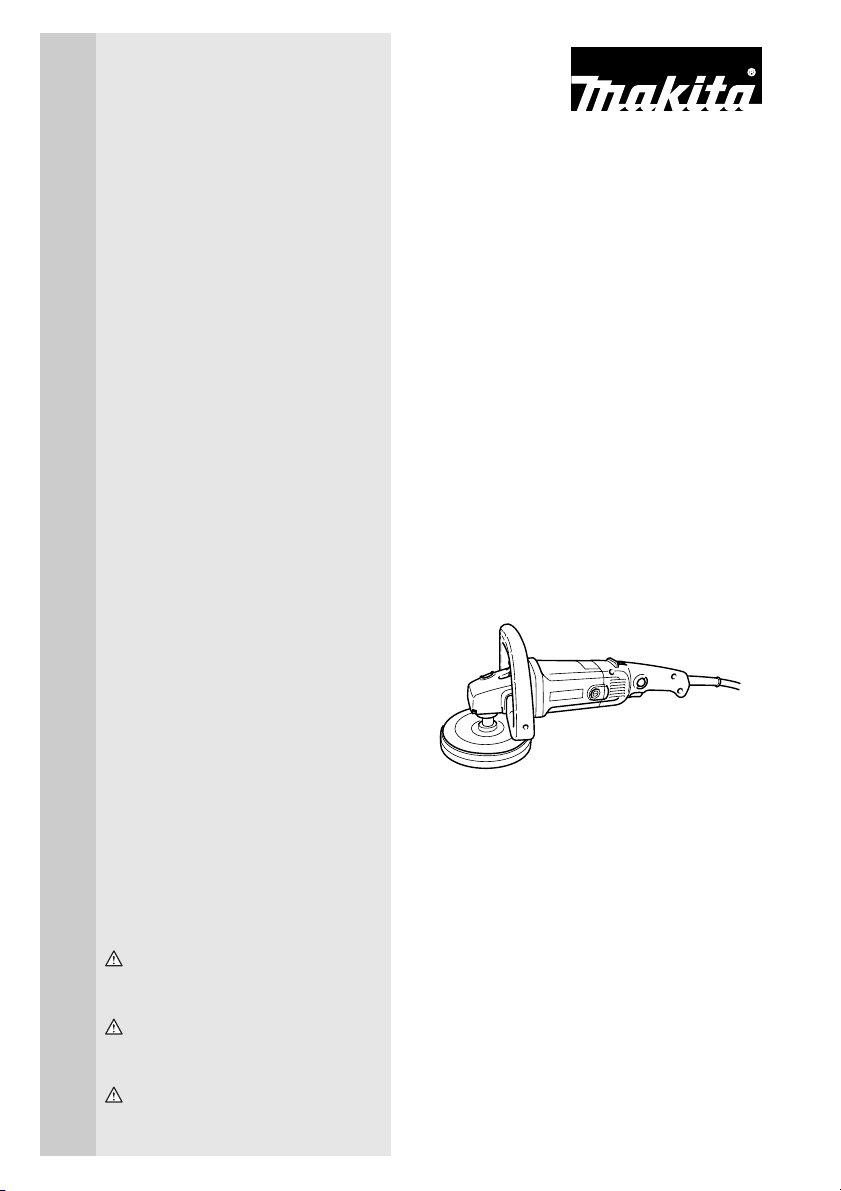
plug that looks like Fig. “A”.
3
Page 4
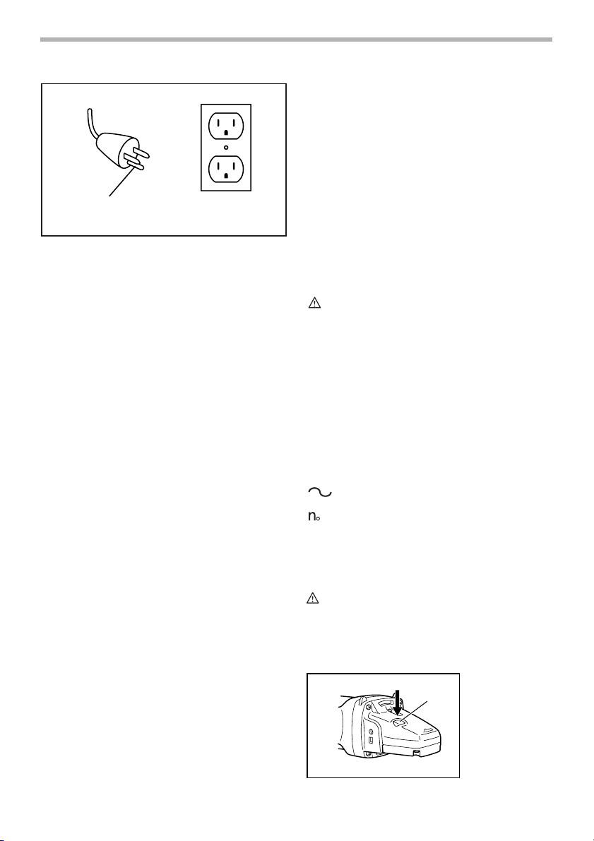
Fig. A
Grounding
Blade
Cover of Grounded
Outlet Box
SPECIFIC SAFETY RULES
USB047-4
DO NOT let comfort or familiarity with
product (gained from repeated use)
replace strict adherence to polisher
safety rules. If you use this tool unsafely
or incorrectly, you can suffer serious personal injury.
1. Accessories must be rated for at least the speed
recommended on the tool warning label. Wheels
and other accessories running over rated speed can
fly apart and cause injury. Maximum operating
speed of accessories should be higher than the
highest no load speed marked on the tool’s nameplate.
2. Hold tool by insulated gripping surfaces when
performing an operation where the cutting tool
may contact hidden wiring or its own cord. Con-
tact with a “live” wire will make exposed metal parts
of the tool “live” and shock the operator.
3. Check the backing pad carefully for cracks, damage or deformity before operation. Replace
cracked, damaged or deformed pad immediately.
4. NEVER use tool with wood cutting blades or
other sawblades. Such blades when used on a
polisher frequently kick and cause loss of control leading to personal injury.
5. Hold the tool firmly.
6. Keep hands away from rotating parts.
7. Make sure the abrasive disc or wool bonnet is
not contacting the workpiece before the switch
is turned on.
8. When sanding metal surfaces, watch out for flying sparks. Hold the tool so that sparks fly away
from you and other persons or flammable materials.
9. Do not leave the tool running. Operate the tool
only when hand-held.
10. Do not touch the workpiece immediately after
operation; it may be extremely hot and could
burn your skin.
11. Check that the workpiece is properly supported.
12. Pay attention that the wheel continues to rotate
after the tool is switched off.
13. This tool has not been waterproofed, so do not
use water on the workpiece surface.
14. Ventilate your work area adequately when you
perform sanding operations.
15. Use of this tool to sand some products, paints
and wood could expose user to dust containing
hazardous substances. Use appropriate respiratory protection.
SAVE THESE INSTRUCTIONS
WARNING:
MISUSE or failure to follow the safety
rules stated in this instruction manual
may cause serious personal injury.
SYMBOLS
The followings show the symbols used for tool.
V ...........................volts
A...........................amperes
Hz .........................hertz
.................. alternating current
...................... no load speed
.../min ...................revolutions or reciprocation per
minute
USD101-2
FUNCTIONAL DESCRIPTION
CAUTION:
• Always be sure that the tool is switched off and
unplugged before adjusting or checking function on
the tool.
Shaft lock
003432
1. Shaft lock
1
4
Page 5
CAUTION:
• Never actuate the shaft lock when the spindle is
moving. The tool may be damaged.
Press the shaft lock to prevent spindle rotation when
installing or removing accessories.
Switch action
1
2
003435
1. Lock button
2. Switch trigger
003441
Number
1
2
3
4
5
6
CAUTION:
• If the tool is operated continuously at low speeds for
a long time, the motor will get overloaded, resulting
in tool malfunction.
• The speed adjusting dial can be turned only as far
as 6 and back to 1. Do not force it past 6 or 1, or the
speed adjusting function may no longer work.
min -1 (RPM
)
600
900
1,500
2,100
2,700
3,000
CAUTION:
• Before plugging in the tool, always check to see
that the switch trigger actuates properly and returns
to the “OFF” position when released.
• Switch can be locked in “ON” position for ease of
operator comfort during extended use. Apply caution when locking tool in “ON” position and maintain
firm grasp on tool.
To star t the tool, simply pull the switch trigger. Tool speed
is increased by increasing pressure on the switch trigger.
Release the switch trigger to stop.
For continuous operation, pull the switch trigger and then
push in the lock button.
To stop the tool from the locked position, pull the switch
trigger fully, then release it.
Speed adjusting dial
The tool speed can be changed by turning the speed
adjusting dial to a given number setting from 1 to 6. (At
the time when the switch trigger is fully pulled.)
Higher speed is obtained when the dial is turned in the
direction of number 6. And lower speed is obtained when
it is turned in the direction of number 1.
Refer to the table for the relationship between the number settings on the dial and the approximate tool speed.
003440
1
1. Speed adjusting dial
ASSEMBLY
CAUTION:
• Always be sure that the tool is switched off and
unplugged before carrying out any work on the tool.
Installing loop handle (For 9227C only)
CAUTION:
• Always be sure that the loop handle is installed
securely before operation.
12
Always install the loop handle on the tool before operation. Hold the tool’s switch handle and the loop handle
firmly with both hands during operation.
Install the loop handle so that its protrusion will fit into the
matching hole in the gear housing.
Install the bolts and tighten them with the hex wrench.
The loop handle can be installed in two different directions as shown in the figures whichever is convenient for
your wor k.
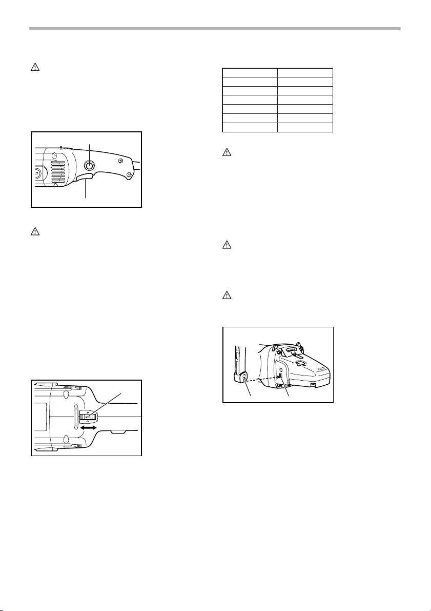
003448
1. Protrusion of
loop handle
2. Matching hole in
gear housing
5
Page 6
003449
1
1. Loop handle
2. Hex wrench
3. Bolt
2
3
003450
11
3
1. Loop handle
2. Bolt
3. Hex wrench
2
Installing side grip (handle) (For 9227CY only)
CAUTION:
• Always be sure that the side grip is installed
securely before operation.
Screw the side grip securely on the position of the tool as
shown in the figure.
003805
Using the sleeve 18 as a positioning guide, install the
wool bonnet on the backing pad with the sleeve 18
inserted through the center hole of the wool bonnet.
Then remove the sleeve 18 from the backing pad.
To remove the wool bonnet, just tear it off the backing
pad. Then unscrew the backing pad while pressing the
shaft lock.
Installing or removing abrasive disc
(optional accessory)
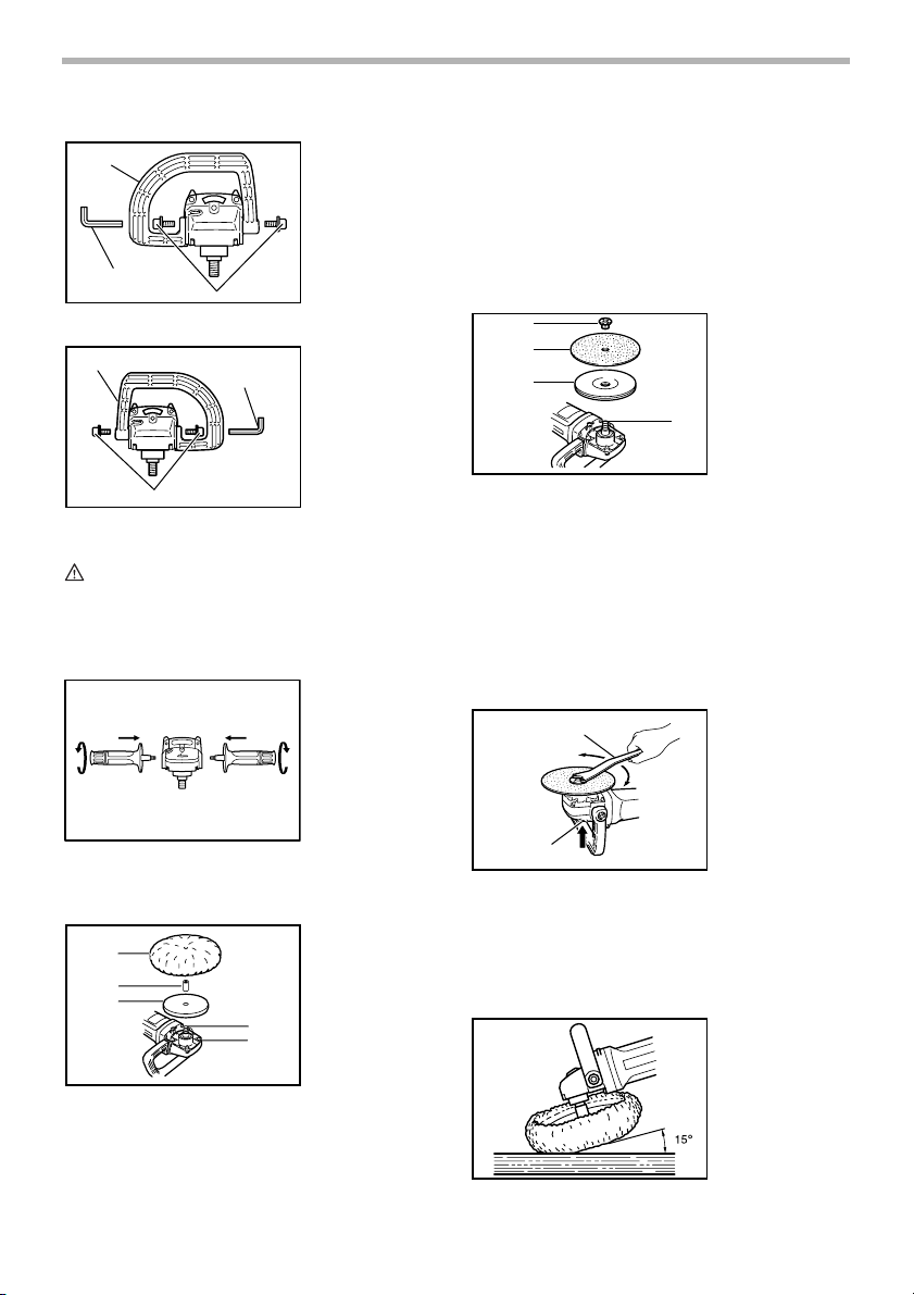
1
2
3
NOTE:
• Use sander accessories specified in this manual.
These must be purchased separately.
Mount the rubber pad onto the spindle. Fit the abrasive
disc on the rubber pad and screw the lock nut onto the
spindle.
To tighten the lock nut, press the shaft lock firmly so that
the spindle cannot revolve, then use the lock nut wrench
and securely tighten clockwise.
1
003457
1. Lock nut
2. Abrasive disc
3. Rubber pad
4. Spindle
4
003458
1. Lock nut wrench
2. Shaft lock
Installing or removing the wool bonnet
(optional accessory)
1
2
3
To install the wool bonnet, first remove all dirt or foreign
matter from the backing pad. Press the shaft lock and
screw the backing pad onto the spindle. Insert the sleeve
18 into the center hole of the backing pad.
003467
4
5
1. Wool bonnet
2. Sleeve 18
3. Backing pad
4. Spindle
5. Shaft lock
2
To remove the disc, follow the installation procedure in
reverse.
OPERATION
Polishing operation
6
003478
Page 7
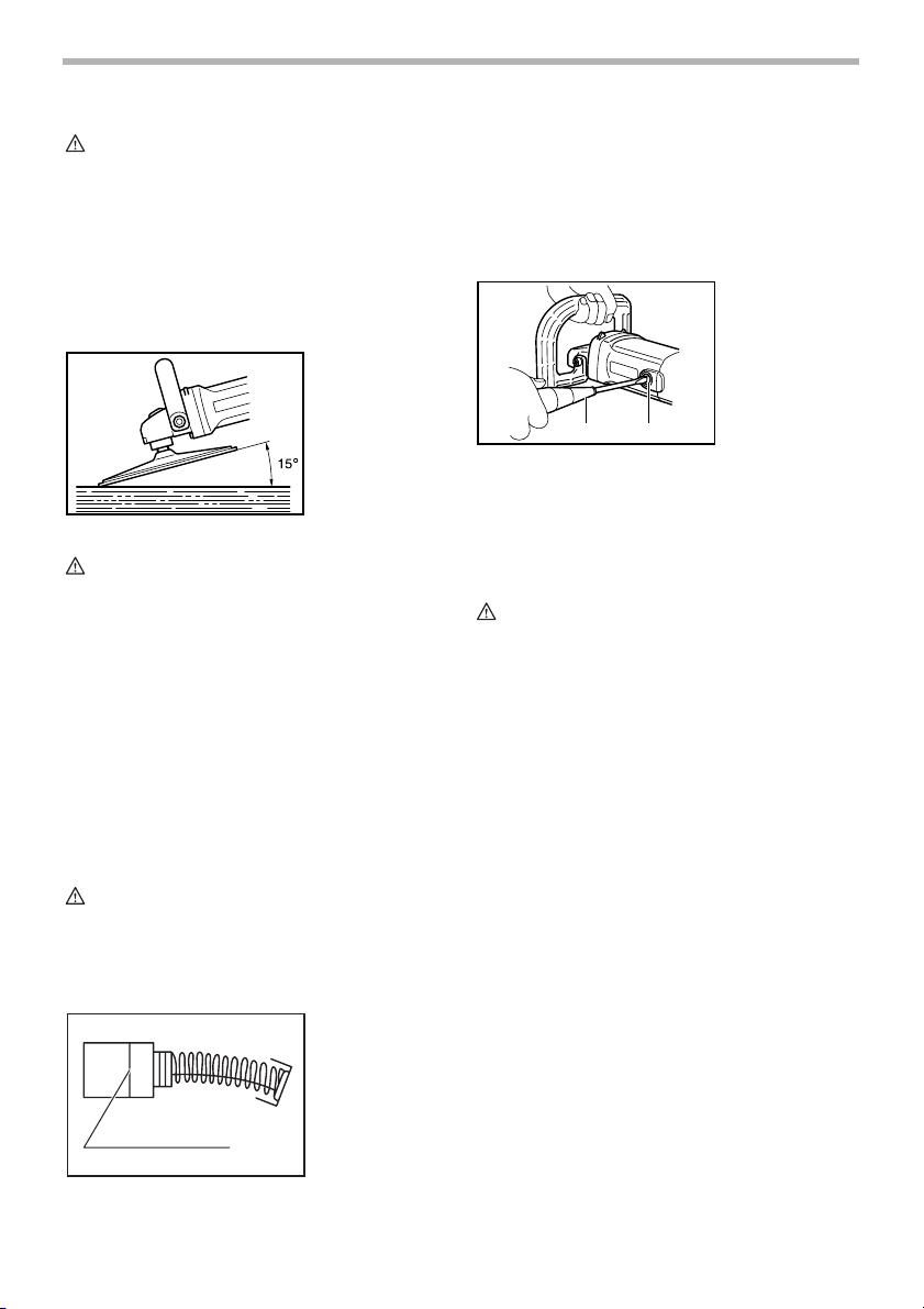
CAUTION:
• Always wear safety glasses or a face shield during
operation.
Hold the tool firmly. Turn the tool on and then apply the
wool bonnet to the workpiece.
In general, keep the wool bonnet at an angle of about 15
degrees to the workpiece surface.
Apply slight pressure only. Excessive pressure will result
in poor performance and premature wear to wool bonnet.
Sanding operation
003473
Remove and check the carbon brushes regularly.
Replace when they wear down to the limit mark. Keep
the carbon brushes clean and free to slip in the holders.
Both carbon brushes should be replaced at the same
time. Use only identical carbon brushes.
Use a screwdriver to remove the brush holder caps. Take
out the worn carbon brushes, insert the new ones and
secure the brush holder caps.
12
To maintain product SAFETY and RELIABILITY, repairs,
any other maintenance or adjustment should be performed by Makita Authorized or Factory Service Centers,
always using Makita replacement parts.
003483
1. Screwdriver
2. Brush holder
cap
CAUTION:
• Always wear safety goggles or a face shield during
operation.
• Never switch on the tool when it is in contact with
the workpiece, it may cause an injury to operator.
• Never run the tool without the abrasive disc. You
may seriously damage the pad.
Hold the tool firmly. Turn the tool on and then apply the
abrasive disc to the workpiece.
In general, keep the abrasive disc at an angle of about 15
degrees to the workpiece surface.
Apply slight pressure only. Excessive pressure will result
in poor performance and premature wear to abrasive
disc.
MAINTENANCE
CAUTION:
• Always be sure that the tool is switched off and
unplugged before attempting to perform inspection
or maintenance.
Replacing carbon brushes
001145
1. Limit mark
1
ACCESSORIES
CAUTION:
• These accessories or attachments are recom-
mended for use with your Makita tool specified in
this manual. The use of any other accessories or
attachments might present a risk of injury to persons. Only use accessory or attachment for its
stated purpose.
If you need any assistance for more details regarding
these accessories, ask your local Makita Service Center.
• Wool bonnet 180 (Hook & loop)
• Backing pad 165 (Hook & loop)
• Abrasive discs
• Rubber pad 170
• Sanding lock nut 5/8 - 48
• Lock nut wrench 28
• Sleeve 18
• Grip 36
• Loop handle
MAKITA LIMITED ONE YEAR WARRANTY
Warranty Policy
Every Makita tool is thoroughly inspected and tested
before leaving the factory. It is warranted to be free of
defects from workmanship and materials for the period of
ONE YEAR from the date of original purchase. Should
any trouble develop during this one year period, return
the COMPLETE tool, freight prepaid, to one of Makita’s
Factory or Authorized Service Centers. If inspection
shows the trouble is caused by defective workmanship or
EN0006-1
7
Page 8

material, Makita will repair (or at our option, replace)
without charge.
This Warranty does not apply where:
• repairs have been made or attempted by others:
• repairs are required because of normal wear and
tear:
• the tool has been abused, misused or improperly
maintained:
• alterations have been made to the tool.
IN NO EVENT SHALL MAKITA BE LIABLE FOR ANY
INDIRECT, INCIDENTAL OR CONSEQUENTIAL DAMAGES FROM THE SALE OR USE OF THE PRODUCT.
THIS DISCLAIMER APPLIES BOTH DURING AND
AFTER THE TERM OF THIS WARRANTY.
MAKITA DISCLAIMS LIABILITY FOR ANY IMPLIED
WARRANTIES, INCLUDING IMPLIED WARRANTIES
OF “MERCHANTABILITY” AND “FITNESS FOR A SPECIFIC PURPOSE,” AFTER THE ONE YEAR TERM OF
THIS WARRANTY.
This Warranty gives you specific legal rights, and you
may also have other rights which vary from state to state.
Some states do not allow the exclusion or limitation of
incidental or consequential damages, so the above limitation or exclusion may not apply to you. Some states do
not allow limitation on how long an implied warranty lasts,
so the above limitation may not apply to you.
8
Page 9

FRANÇAIS
SPÉCIFICATIONS
Modèle 9227C/9227CY
Capacités max.
Filetage de l’arbre 5/8”
Vitesse à vide (T/MIN) 0 - 3,000/min.
Longueur totale 470 mm (18-1/2”)
• Le fabricant se réserve le droit de modifier sans avertissement les spécifications.
• Note: Les spécifications peuvent varier selon les pays.
Plateau peau de mouton 180 mm (7”)
Disque abrasif 180 mm (7”)
Poids net 3.0 kg (6.6 lbs)
RÈGLES DE SÉCURITÉ
GÉNÉRALES
USA001-3
(Pour tous les outils)
AVERTISSEMENT:
Vous devez lire et comprendre toutes les
instructions. Le non-respect, même partiel,
des instructions ci-après entraîne un risque
de choc électrique, d’incendie et/ou de
blessures graves.
CONSERVEZ CES
INSTRUCTIONS
Aire de travail
1. Veillez à ce que l’aire de travail soit propre et
bien éclairée. Le désordre et le manque de lumière
favorisent les accidents.
2. N’utilisez pas d’outils électriques dans une
atmosphère explosive, par exemple en présence
de liquides, de gaz ou de poussières
inflammables. Les outils électriques créent des
étincelles qui pourraient enflammer les poussières
ou les vapeurs.
3. Tenez à distance les curieux, les enfants et les
visiteurs pendant que vous travaillez avec un
outil électrique. lls pourraient vous distraire et vous
faire une fausse manoeuvre.
Sécurité électrique
4. Les outils mis à la terre doivent être branchés
dans une prise de courant correctement
installée et mise à la terre conformément à tous
les codes et règlements pertinents. Ne modifiez
jamais la fiche de quelque façon que ce soit, par
exemple en enlevant la broche de mise à la terre.
N’utilisez pas d’adaptateur de fiche. Si vous
n’êtes pas certain que la prise de courant est
correctement mise à la terre, adressez-vous à un
électricien qualifié. En cas de défaillance ou de
défectuosité électrique de l’outil, une mise à la terre
offre un trajet de faible résistance à l’électricité qui
autrement risquerait de traverser l’utilisateur.
5. Évitez tout contact corporel avec des surfaces
mises à la terre (tuyauterie, radiateurs,
cuisinières, réfrigérateurs, etc.). Le risque de
choc électrique est plus grand si votre corps est en
contact avec la terre.
6. N’exposez pas les outils électriques à la pluie ou
à l’eau. La présence d’eau dans un outil électrique
augmente le risque de choc électrique.
7. Ne maltraitez pas le cordon. Ne transportez pas
l’outil par son cordon et ne débranchez pas la
fiche en tirant sur le cordon. N’exposez pas le
cordon à la chaleur, à des huiles, à des arêtes
vives ou à des pièces en mouvement.
Remplacez immédiatement un cordon
endommagé. Un cordon endommagé augmente le
risque de choc électrique.
8. Lorsque vous utilisez un outil électrique à
l’extérieur, employez un prolongateur pour
l’extérieur marqué “W-A” ou “W”. Ces cordons
sont faits pour être utilisés à l’extérieur et réduisent
le risque de choc électrique.
Sécurité des personnes
9. Restez alerte, concentrez-vous sur votre travail
et faites preuve de jugement. N’utilisez pas un
outil électrique si vous êtes fatigué ou sous
l’influence de drogues, d’alcool ou de
médicaments. Un instant d’inattention suffit pour
entraîner des blessures graves.
10. Habillez-vous convenablement. Ne portez ni
vêtements flottants ni bijoux. Confinez les
cheveux longs. N’approchez jamais les
cheveux, les vêtements ou les gants des pièces
en mouvement. Des vêtements flottants, des bijoux
9
Page 10

ou des cheveux longs risquent d’être happés par
des pièces en mouvement.
11. Méfiez-vous d’un démarrage accidentel. Avant
de brancher l’outil, assurez-vous que son
interrupteur est sur ARRÊT. Le fait de transporter
un outil avec le doigt sur la détente ou de brancher
un outil dont l’interrupteur est en position MARCHE
peut mener tout droit à un accident.
12. Enlevez les clés de réglage ou de serrage avant
de démarrer l’outil. Une clé laissée dans une pièce
tournante de l’outil peut provoquer des blessures.
13. Ne vous penchez pas trop en avant. Maintenez
un bon appui et restez en équilibre en tout
temps. Un bonne stabilité vous permet de mieux
réagir à une situation inattendue.
14. Utilisez des accessoires de sécurité. Portez
toujours des lunettes ou une visière. Selon les
conditions, portez aussi un masque antipoussière,
des bottes de sécurité antidérapantes, un casque
protecteur et/ou un appareil antibruit. Les lunettes
ordinaires et les lunettes de soleil NE constituent
PAS des lunettes de protection.
Utilisation et entretien des outils
15. Immobilisez le matériau sur une surface stable
au moyen de brides ou de toute autre façon
adéquate. Le fait de tenir la pièce avec la main ou
contre votre corps offre une stabilité insuffisante et
peut amener un dérapage de l’outil.
16. Ne forcez pas l’outil. Utilisez l’outil approprié à
la tâche. L’outil correct fonctionne mieux et de façon
plus sécuritaire. Respectez aussi la vitesse de
travail qui lui est propre.
17. N’utilisez pas un outil si son interrupteur est
bloqué. Un outil que vous ne pouvez pas
commander par son interrupteur est dangereux et
doit être réparé.
18. Débranchez la fiche de l’outil avant d’effectuer
un réglage, de changer d’accessoire ou de
ranger l’outil. De telles mesures préventives de
sécurité réduisent le risque de démarrage accidentel
de l’outil.
19. Rangez les outils hors de la portée des enfants
et d’autres personnes inexpérimentées. Les
outils sont dangereux dans les mains d’utilisateurs
novices.
20. Prenez soin de bien entretenir les outils. Les
outils de coupe doivent être toujours bien
affûtés et propres. Des outils bien entretenus, dont
les arêtes sont bien tranchantes, sont moins
susceptibles de coincer et plus faciles à diriger.
21. Soyez attentif à tout désalignement ou
coincement des pièces en mouvement, à tout
bris ou à toute autre condition préjudiciable au
bon fonctionnement de l’outil. Si vous constatez
qu’un outil est endommagé, faites-le réparer
avant de vous en servir. De nombreux accidents
sont causés par des outils en mauvais état.
22. N’utilisez que des accessoires que le fabricant
recommande pour votre modèle d’outil. Certains
accessoires peuvent convenir à un outil, mais être
dangereux avec un autre.
RÉPARATI ON
23. La réparation des outils électriques doit être
confiée à un réparateur qualifié. L’entretien ou la
réparation d’un outil électrique par un amateur peut
avoir des conséquences graves.
24. Pour la réparation d’un outil, n’employez que
des pièces de rechange d’origine. Suivez les
directives données à la section «ENTRETIEN» de
ce manuel. L’emploi de pièces non autorisées ou le
non-respect des instructions d’entretien peut créer
un risque de choc électrique ou de blessures.
UTLISEZ UN CORDON PROLONGATEUR ADÉQUAT:
N’utilisez que les cordons prolongateurs à trois fils
et munis d’une fiche tripolaire, ainsi que des prises
tripolaires adaptées à la fiche de l’outil. Assurezvous que le cordon prolongateur est en bon état.
Remplacez ou réparez sans tarder tout cordon
endommagé ou usé. Lors de l’utilisation d’un cordon
prolongateur, utilisez sans faute un cordon assez
gros pour conduire le courant que le produit
nécessite. Un cordon trop petit provoquera une
baisse de tension de secteur, résultant en une perte
de puissance et une surchauffe. Le Tableau 1 indique
la dimension appropriée de cordon selon sa
longueur et selon l’intensité nominale indiquée sur la
plaque signalétique. En cas de doute sur un cordon
donné, utilisez le cordon suivant (plus gros). Plus le
numéro de gabarit indiqué est petit, plus le cordon
est gros.
Tableau 1: Gabarit minimum du cordon
Intensité nominale
Volts Longueur totale du cordon en pieds
120 V 25 pi 50 pi 100 pi 150 pi
Plus de Pas plus de Calibre américain des fils
0 6 18 16 16 14
6 10 18161412
10 12 16 16 14 12
12 16 14 12 Non recommandé
10
Page 11

INSTRUCTIONS POUR LA MISE À TERRE:
Cet outil doit être mis à la terre pendant son
utilisation, afin de protéger son utilisateur contre les
chocs électriques. Il est équipé d’un cordon à trois
conducteurs et d’une fiche tripolaire adaptée au type
de prise correspondant. Le conducteur vert (ou vert
et jaune) du cordon est le fil de mise à la terre. Ne
raccordez jamais ce fil vert (ou vert et jaune) à une
borne d’alimentation secteur. Cet appareil doit être
utilisé sur un circuit de 120 volts et sa fiche est telle
qu’illustrée sur la Fig. “A”.
Fig. A
Lame de mise à la terre
Couvercle de la prise
d’alimentation mise à
la terre
RÈGLES DE SÉCURITÉ
PARTICULI ÈRES
USB047-4
NE vous laissez PAS tromper (au fil d’une
utilisation répétée) par un sentiment
d’aisance et de familiarité avec le
produit, en négligeant le respect
rigoureux des consignes de sécurité qui
accompagnent la polisseuse.
L’utilisation non sécuritaire ou incorrecte
de cet outil comporte un risque de
blessure grave.
1. Les accessoires doivent être prévus pour au
moins la vitesse recommandée sur l’étiquette de
mise en garde de l’outil. Les meules et autres
accessoires, s’il tournent au-delà de la vitesse
nominale, risquent d’éclater et de provoquer des
blessures. La vitesse maximale de fonctionnement
des accessoires doit être supérieure à la vitesse
maximale à vide indiquée sur la plaque signalétique
de l’outil.
2. Tenez l’outil par ses surfaces de prise isolées
pendant toute opération où l’outil de coupe
pourrait venir en contact avec un câblage
dissimulé ou avec son propre cordon. En cas de
contact avec un conducteur sous tension, les pièces
métalliques à découvert de l’outil transmettraient un
choc électrique à l’utilisateur.
3. Avant d’opérer, assurez-vous que le plateau
caoutchouc ne présente ni fissure, ni
déformation, ni défaut d’aucune sorte. Si c’était
le cas, changez-le immédiatement.
4. N’utilisez JAMAIS cet outil avec des lames à bois
ou autres lames de scie. Les lames de ce type
sautent fréquemment lorsque utilisées sur une
polisseuse et peuvent alors entraîner une perte
de contrôle pouvant causer des blessures.
5. Tenez votre outil fermement.
6. Gardez les mains éloignées des pièces en
mouvement.
7. Assurez-vous que le disque abrasif ou la peau
de mouton n’entre pas en contact avec la pièce à
travailler avant de mettre l’interrupteur sous
tension.
8. Lors du ponçage de surfaces métalliques, faites
attention aux étincelles. Placez-vous de telle
manière que personne (vous y compris) ne se
trouve sur le trajet des particules
incandescentes. Veillez également à les
maintenir à l’écart de tout produit inflammable.
9. N’abandonnez pas l’outil en fonctionnement : il
ne doit rester en marche que si vous l’avez en
main.
10. La surface qui vient d’être poncée ou polie peut
être très chaude; ne la touchez pas pour ne pas
vous brûler.
11. Vérifiez que la pièce est correctement soutenue.
12. Soyez conscient que la meule continue de
tourner une fois l’outil mis hors tension.
13. Cet outil n’ayant pas été imperméabilisé, la
surface de la pièce à travailler doit être exempte
d’eau lors de son utilisation.
14. Aérez adéquatement l’aire de travail lorsque
vous effectuez des travaux de ponçage.
15. L’utilisation de cet outil pour poncer certains
produits, les surfaces peintes et le bois peut
exposer l’utilisateur à des poussières qui
contiennent des substances dangereuses.
Veuillez porter une protection des voies
respiratoires adéquate.
CONSERVEZ CES
INSTRUCTIONS
AVERTISSEMENT:
LA MAUVAISE UTILISATION de l’outil ou
l’ignorance des consignes de sécurité du
présent manuel d’instructions peut
entraîner une blessure grave.
11
Page 12

SYMBOLES
Les symboles utilisés pour l’outil sont indiqués cidessous.
V............................volts
A ...........................ampères
Hz..........................hertz
..................courant alternatif
.......................vitesse à vide
.../min....................tours par minute
USD101-2
DESCRIPTION DU
FONCTIONNEMENT
ATTENTION:
• Assurez-vous toujours que l’outil est hors tension et
débranché avant de l’ajuster ou de vérifier son
fonctionnement.
Blocage de l’arbre
ATTENTION:
• N’activez jamais le blocage de l’arbre alors que
l’arbre bouge. Vous pourriez endommager l’outil.
Appuyez sur le blocage de l’arbre pour empêcher l’arbre
de tourner lors de l’installation ou du retrait des
accessoires.
Interrupteur
1
003432
1. Verrou d’axe
1
003435
1. Bouton de
verrouillage
2. Gâchette
ATTENTION:
• Avant de brancher l’outil, assurez-vous toujours
que la gâchette fonctionne correctement et revient
en position d’arrêt une fois relâchée.
• Pour rendre le travail de l’utilisateur plus confortable
lors d’une utilisation prolongée, l’interrupteur peut
être verrouillé en position de marche. Soyez
prudent lorsque vous verrouillez l’outil en position
de marche, et maintenez une poigne solide sur
l’outil.
Pour mettre l’outil en marche, appuyez simplement sur la
gâchette. La vitesse de l’outil augmente à mesure que
l’on accroît la pression exercée sur la gâchette. Pour
l’arrêter, relâchez la gâchette.
Pour un fonctionnement continu, appuyez sur la gâchette
puis enfoncez le bouton de verrouillage.
Pour arrêter l’outil alors qu’il est en position verrouillée,
appuyez à fond sur la gâchette puis relâchez-la.
Cadran de rélage de vitesse
La vitesse de l’outil peut être modifiée en tournant le
cadran de réglage de la vitesse sur un numéro de
réglage donné, de 1 à 6. (au moment où la gâchette est
tirée à fond)
Une vitesse plus élevée est obtenue lorsque le cadran
est tourné dans le sens du numéro 6. Une vitesse plus
basse est obtenue lorsqu’il est tourné dans le sens du
numéro 1.
Reportez-vous au tableau pour le rapport entre les
réglages numérotés sur le cadran et la vitesse
approximative de l’outil.
Nombre
1
2
3
4
5
6
T/MIN
600
900
1,500
2,100
2,700
3,000
003440
1
003441
1. Cadran de
réglage de la
vitesse
ATTENTION:
• Si l’outil est utilisé de manière continue à vitesse
2
réduite sur une période prolongée, le moteur sera
surchargé et cela entraînera un mauvais
fonctionnement de l’outil.
12
Page 13

• Le cadran de réglage de la vitesse ne peut pas
dépasser le 6 et le 1. Ne le forcez pas à dépasser le
6 ou le 1, sinon la fonction de réglage de la vitesse
risque de ne plus fonctionner.
ASSEMBLAGE
ATTENTION:
• Avant d’effectuer toute intervention sur l’outil,
assurez-vous toujours qu’il est hors tension et
débranché.
Installation de la poignée arceau
(pour 9227C uniquement)
ATTENTION:
• Avant l’utilisation, assurez-vous toujours que la
poignée arceau est solidement installée.
12
Installez toujours la poignée arceau sur l’outil avant le
travail. Tenez la poignée arrière de l’outil et la poignée
arceau fermement à deux mains pendant le
fonctionnement.
Installez la poignée arceau de façon que sa saillie rentre
dans l’orifice correspondant du carter d’engrenages.
Installez les boulons et serrez-les à l’aide de la clé
hexagonale. Vous pouvez installer la poignée arceau
dans deux directions différentes, comme indiqué sur les
figures, en fonction du travail à effectuer.
1
2
003448
1. Partie saillante
de la poignée
arceau
2. Orifice de
couplage dans
le carter
d’engrenages
003449
1. Poignée arceau
2. Clé hexagonale
3. Boulon
3
003450
11
2
3
1. Poignée arceau
2. Boulon
3. Clé hexagonale
Installation de la poignée latérale (poignée)
(pour 9227CY uniquement)
ATTENTION:
• Avant d’utiliser l’outil, assurez-vous toujours que la
poignée latérale est installée de façon sûre.
Vissez la poignée latérale à fond sur la position de l’outil
comme illustré sur la figure.
003805
Installation ou retrait de la peau de mouton
(accessoire en option)
1
2
3
Avant d’installer la peau de mouton, enlevez toute saleté
et tout corps étranger du plateau. Appuyez sur le verrou
d’axe et vissez le plateau de support sur l’arbre. Insérez
le manchon 18 dans l’orifice central du plateau de
support.
En vous servant du manchon 18 comme guide de
positionnement, installez la peau de mouton sur le
plateau de support avec le manchon 18 inséré dans
l’orifice central de la peau de mouton. Puis, retirez le
manchon 18 de la peau.
Pour retirer la peau de mouton, enlevez-la simplement du
plateau. Puis, dévissez le plateau tout en appuyant sur le
verrou d’axe.
003467
4
5
1. Peau de mouton
2. Manchon 18
3. Plateau de
support
4. Arbre
5. Verrou d’axe
13
Page 14

Installation ou retrait du disque abrasif
(accessoire en option)
1
2
3
NOTE:
• Utilisez les accessoires de ponçage recommandés
dans le présent manuel d’instructions. Ces derniers
doivent être achetés séparément.
Placez le plateau de caoutchouc sur l’arbre. Ajustez le
disque abrasif sur le plateau de caoutchouc et vissez le
contre-écrou sur l’arbre.
Pour serrer le contre-écrou, appuyez fermement sur le
blocage de l’arbre pour empêcher l’arbre de tourner, puis
utilisez la clé à contre-écrou en serrant fermement dans
le sens des aiguilles d’une montre.
1
2
Pour retirer le disque, suivez la procédure d’installation
de l’autre côté.
003457
1. Contre-écrou
2. Disque abrasif
3. Plateau de
4. Arbre
4
003458
1. Clé à ergots
2. Verrou d’axe
caoutchouc
UTILISATION
Opération de polissage
003478
Tene z l’outil fermement. Mettez le contact et appliquez
ensuite la peau de mouton sur le matériau.
D’une façon générale, maintenez la peau de mouton
selon un angle d’environ 15 degrés avec la surface du
matériau.
N’appliquez qu’une légère pression ; toute pression
excessive réduit le rendement de l’outil et entraîne une
usure prématurée de la peau de mouton.
Opération de sablage
ATTENTION:
• Portez toujours des lunettes à coques de sécurité
ou un écran facial pendant l’opération.
• Ne mettez jamais l’outil en marche alors qu’il se
trouve en contact avec la pièce à travailler, pour
éviter de vous blesser.
• Ne jamais utiliser l’outil sans le disque abrasif. Vous
risquer de sérieusement endommager le tampon.
Tene z l’outil fermement. Mettez le contact et appliquez
ensuite le disque abrasif sur le matériau.
D’une façon générale, maintenez le disque abrasif selon
un angle d’environ 15 degrés avec la surface du
matériau.
N’appliquez qu’une légère pression ; toute pression
excessive réduit le rendement de l’outil et entraîne une
usure prématurée du disque abrasif.
003473
ENTRETIEN
ATTENTION:
• Assurez-vous toujours que l’outil est hors tension et
débranché avant d’y effectuer tout travail
d’inspection ou d’entretien.
Remplacement des charbons
001145
1. Trait de limite
d’usure
ATTENTION:
• Portez toujours des lunettes à coques de sécurité
ou un écran facial pendant l’opération.
1
14
Page 15

Retirez et vérifiez régulièrement les charbons.
Remplacez-les lorsqu’ils sont usés jusqu’au trait de limite
d’usure. Maintenez les charbons propres et en état de
glisser aisément dans les porte-charbon. Les deux
charbons doivent être remplacés en même temps.
N’utilisez que des charbons identiques.
Utilisez un tournevis pour retirer les bouchons de portecharbon. Enlevez les charbons usés, insérez-en de
nouveaux et revissez solidement les bouchons de portecharbon.
12
Pour maintenir la SÉCURITÉ et la FIABILITÉ du produit,
les réparations, tout autre travail d’entretien ou de
réglage doivent être effectués dans un centre de service
Makita agréé ou un centre de service de l’usine Makita,
exclusivement avec des pièces de rechange Makita.
003483
1. Tournevis
2. Bouchon de
porte-charbon
ACCESSOIRES
ATTENTION:
• Ces accessoires ou pièces complémentaires sont
recommandés pour l’utilisation avec l’outil Makita
spécifié dans ce mode d’emploi. L’utilisation de tout
autre accessoire ou pièce complémentaire peut
comporter un risque de blessure. N’utilisez les
accessoires ou pièces qu’aux fins auxquelles ils ont
été conçus.
Si vous désirez obtenir plus de détails concernant ces
accessoires, veuillez contacter le centre de service
après-vente Makita le plus près.
• Peau de mouton 180 (auto-agrippante)
• Plateau de support 165 (auto-aggripant)
• Disques abrasifs
• Plateau de caoutchouc 170
• Contre-écrou pour ponçage 5/8 - 48
• Clé àergots 28
• Manchon 18
• Poignée 36
• Poignée arceau
GARANTIE LIMITÉE D’UN AN MAKITA
EN0006-1
Politique de garantie
Chaque outil Makita est inspecté rigoureusement et testé
avant sa sortie d’usine. Nous garantissons qu’il sera
exempt de défaut de fabrication et de vice de matériau
pour une période d’UN AN à partir de la date de son
achat initial. Si un problème quelconque devait survenir
au cours de cette période d’un an, veuillez retourner
l’outil COMPLET, port payé, à une usine ou à un centre
de service après-vente Makita. Makita réparera l’outil
gratuitement (ou le remplacera, à sa discrétion) si un
défaut de fabrication ou un vice de matériau est
découvert lors de l’inspection.
Cette garantie ne s’applique pas dans les cas où :
• des réparations ont été effectuées ou tentées par
un tiers ;
• des réparations s’imposent suite à une usure
normale ;
• l’outil a été malmené, mal utilisé ou mal entretenu ;
• l’outil a subi des modifications.
MAKITA DÉCLINE TOUTE RESPONSABILITÉ POUR
TOUT DOMMAGE ACCESSOIRE OU INDIRECT LIÉ À
LA VENTE OU À L’UTILISATION DU PRODUIT. CET
AVIS DE NON-RESPONSABILITÉ S’APPLIQUE À LA
FOIS PENDANT ET APRÈS LA PÉRIODE COUVERTE
PAR CETTE GARANTIE.
MAKITA DÉCLINE TOUTE RESPONSABILITÉ QUANT
À TOUTE GARANTIE TACITE, INCLUANT LES
GARANTIES TACITES DE “QUALITÉ MARCHANDE” ET
“ADÉQUATION À UN USAGE PARTICULIER” APRÈS
LA PÉRIODE D’UN AN COUVERTE PAR CETTE
GARANTIE.
Cette garantie vous donne des droits spécifiques
reconnus par la loi, et possiblement d’autres droits, qui
varient d’un État à l’autre. Certains États ne permettant
pas l’exclusion ou la limitation des dommages
accessoires ou indirects, il se peut que la limitation ou
exclusion ci-dessus ne s’applique pas à vous. Certains
États ne permettant pas la limitation de la durée
d’application d’une garantie tacite, il se peut que la
limitation ci-dessus ne s’applique pas à vous.
15
Page 16

ESPAÑOL
ESPECIFICACIONES
Modelo 9227C/9227CY
Especificaciones eléctricas en México
Capacidades máximas
Rosca del eje 5/8”
Revoluciones por minuto (r.p.m.) 0 - 3 000/min.
Longitud total 470 mm (18-1/2”)
Peso neto 3,0 kg (6,6 lbs)
• Debido a un programa continuo de investigación y desarrollo, las especificaciones aquí dadas están sujetas a
cambios sin previo aviso.
• Nota: Las especificaciones pueden ser diferentes de país a país.
Disco pulidor de lana 180 mm (7”)
Disco abrasivo 180 mm (7”)
120 V 10 A 50/60 Hz
REGLAS GENERALES DE
SEGURIDAD
USA001-3
(Para todas las herramientas)
AVISO:
Lea y entienda todas las instrucciones.
Si no cumple con las instrucciones aquí
detalladas, se puede producir una descarga
eléctrica, incendio y/o lesiones de gravedad.
GUARDE ESTAS
INSTRUCCIONES
Área de trabajo
1. Mantenga el área de trabajo limpia y bien
iluminada. Las áreas oscuras y mesas de trabajo
desordenadas son propensas a accidentes.
2. No opere herramientas eléctricas en atmósferas
explosivas tales como en presencia de polvo,
gases o líquidos inflamables. Las herramientas
eléctricas producen chispas que puede encender el
polvo o los gases.
3. Mantenga a los niños, espectadores y visitantes
alejados mientras opera la herramienta eléctrica.
Si se distrae, puede perder el control de la
herramienta.
Seguridad en materia de electricidad
4. Las herramientas con toma a tierra deben
enchufarse en un tomacorriente instalado
apropiadamente y conectado a tierra según
todos los códigos y ordenanzas. Nunca retire la
conexión a tierra o modifique la ficha de ninguna
manera. No use fichas para adaptadores.
Verifique con un electricista calificado si tiene
dudas acerca de si el tomacorriente está
conectado a tierra adecuadamente. Si las
herramientas funcionaran mal o fallaran, la conexión
a tierra le brinda un camino de baja resistencia para
llevar la electricidad fuera del usuario.
5. Evite el contacto corporal con superficies a
tierra tales como radiadores, tuberías,
refrigeradores y hornillos. Se corre más riesgo de
sufrir una descarga eléctrica si el cuerpo está a
tierra.
6. No exponga las herramientas eléctricas a la
lluvia o a la humedad. Si ingresa agua en la
herramienta eléctrica, aumenta el riesgo de sufrir
una descarga eléctrica.
7. No tire del cable. Nunca use un cable para
transportar las herramientas ni tire de la ficha
enchufada en un tomacorriente. Mantenga el
cable alejado del calor, aceite, objetos cortantes
o piezas móviles. Reemplace los cables dañados
inmediatamente. Los cables dañados aumentan el
riesgo de sufrir una descarga eléctrica.
8. Cuando opere una herramienta eléctrica al aire
libre, utilice un cable externo marcado “W-A” o
“W”. Estos cables están clasificados para uso
externo y reducen el riesgo de sufrir una descarga
eléctrica.
Seguridad personal
9. Esté atento, preste atención a lo que está
haciendo y utilice su sentido común cuando
opere una herramienta eléctrica. No utilice la
herramienta eléctrica cuando esté cansado o
bajo la influencia de drogas, alcohol o
medicamentos. Un momento de distracción
mientras opera herramientas eléctricas puede dar
como resultado heridas personales graves.
16
Page 17

10. Use vestimenta apropiada. No use ropas sueltas
ni joyas. Átese el cabello largo. Mantenga el
cabello, la ropa y los guantes alejados de las
partes móviles. Las ropas sueltas, joyas o el
cabello largo pueden ser atrapados por las partes
móviles.
11. Evite el encendido accidental de la herramienta.
Asegúrese de que el interruptor está en posición
de apagado antes de enchufarla. Tra n spo r t a r
herramientas con su dedo en el interruptor o
enchufar herramientas que tienen el interruptor en la
posición de encendido hacen propensos los
accidentes.
12. Retire las llaves de ajuste o tuercas antes de
encender la herramienta. Si deja alguna de éstas
adherida a una parte giratoria de la herramienta
eléctrica puede sufrir heridas personales.
13. No haga demasiadas cosas al mismo tiempo.
Mantenga la postura y el equilibrio en todo
momento. Una postura y equilibrio apropiados le
permitirán un mejor control de la herramienta en
situaciones imprevistas.
14. Utilice equipos de seguridad. Utilice siempre
protección ocular. Deben utilizarse máscaras para
protegerse del polvo, calzado de seguridad
antideslizante, casco rígido o protección auditiva
para condiciones apropiadas. Los anteojos
comunes o para el sol NO son gafas de seguridad.
Uso y cuidado de la herramienta
15. Utilice abrazaderas u otra forma práctica de
asegurar y soportar la pieza a una plataforma
estable. Sostener la pieza de trabajo con la mano o
contra su cuerpo es instable y puede llevar a una
pérdida del control.
16. No fuerce la herramienta. Utilice la herramienta
correcta para su aplicación. La herramienta
adecuada hará un trabajo mejor y más seguro a la
velocidad para la que ha sido fabricada.
17. No utilice la herramienta si el interruptor no la
enciende o apaga. Toda herramienta que no pueda
controlarse con el interruptor es peligrosa y debe
repararse.
18. Desconecte la ficha de la fuente de energía antes
de hacer cualquier ajuste, cambiar accesorios o
guardar la herramienta. Dichas medidas
preventivas de seguridad reducen el riesgo de que
la herramienta se opere accidentalmente.
19. Guarde las herramientas que no use fuera del
alcance de los niños y de cualquier otra persona
que no esté familiarizada con el uso de las
mismas. Las herramientas son peligrosas en
manos de personas que no saben operarlas.
20. Cuide sus herramientas. Mantenga las
herramientas de corte limpias y filosas. Si recibe
un mantenimiento adecuado y tiene los bordes
afilados, es probable que la herramienta se atasque
menos y sea más fácil controlarla.
21. Verifique que no esté mal alineada, uniones de
las partes móviles, piezas rotas y demás
condiciones que puedan afectar el
funcionamiento de la herramienta. Si se daña,
repárela antes de usarla. Muchos accidentes son
consecuencia del mal mantenimiento de las
herramientas eléctricas.
22. Utilice sólo accesorios recomendados por el
fabricante para dicho modelo. Los accesorios que
pueden ser adecuados para una herramienta,
pueden ser peligrosos cuando se utilizan en otra
herramienta.
REPARACIÓN
23. Sólo personal calificado deberá realizar la
reparación de la herramienta. La reparación o
mantenimiento realizado por personal no calificado
podría resultar en un riesgo de lesión.
24. Cuando realice reparaciones sólo reemplace por
partes idénticas. Siga las instrucciones de la
sección de Mantenimiento del presente manual.
El uso de partes no autorizadas o la falta de
cumplimiento de las instrucciones de Mantenimiento
podrían crear un riesgo de sufrir una descarga
eléctrica o lesión.
UTILICE UN CABLE DE EXTENSIÓN ADECUADO:
Utilice sólo cables de extensión de tres conductores
que tienen fichas de tres clavijas a tierra y
receptáculos de tres polos que aceptan la ficha de la
herramienta. Asegúrese de que el cable de extensión
esté en buenas condiciones. Reemplace o repare el
cable dañado o gastado inmediatamente. Cuando
use un cable de extensión, asegúrese de que éste
sea lo suficientemente potente como para soportar
la tensión eléctrica que producirá el uso de la
herramienta. Un cable demasiado delgado producirá
una reducción del voltaje, lo que ocasionará una
disminución en la corriente y sobrecalentamiento. La
tabla 1 muestra el tamaño correcto de cable,
dependiendo de la longitud y del rango de amperio
establecido en la placa de fábrica. Si se encuentra en
duda, utilice uno más potente. Cuanto más pequeño
sea el número del calibre, más potente será el cable.
17
Page 18

Tabla 1: Calibre mínimo para el cable
Rango de amperio
Voltios Largo total del cable en centímetros
120 V 762 cm 1.524 cm 3.048 cm 4.572 cm
Más de No más de AWG
0 6 18 16 16 14
6 10 18161412
10 12 16 16 14 12
12 16 14 12 No se recomienda
INTRUCCIONES PARA CONEXIÓN A TIERRA:
Esta herramienta deberá ser conectada a tierra
mientras está en uso para proteger al operador de
sufrir una descarga eléctrica. La herramienta está
equipada con un cable de tres conductores y una
ficha de tres clavijas para conexión a tierra para
adaptarse al receptáculo apropiado de conexión a
tierra. El conductor verde (o verde y amarillo) en el
cable es el conductor de conexión a tierra. Nunca
conecte el conductor verde (o verde y amarillo) a un
terminal vivo. Su unidad es para usar en 120 voltios y
tiene una ficha igual que la que aparece en la Figura
“A”.
Fig. A
Clavija de conexion a tierra
Cubierta de la caja
del tomacorriente
conectada a tierra
REGLAS ESPECÍFICAS DE
SEGURIDAD
USB047-4
NO permita que la comodidad o
familiaridad con el producto (a causa de
su uso frecuente) substituya el
cumplimiento estricto de las reglas de
seguridad sobre la pulidora. Si usted
utiliza esta herramienta de modo
inseguro o incorrecto, puede sufrir
heridas graves.
1. Los accesorios deben poseer al menos la
velocidad recomendada en la etiqueta de
advertencia que lleva la herramienta. Las ruedas
y demás accesorios que funcionen por encima de la
velocidad estipulada podrían salir volando y causar
heridas. La velocidad máxima de funcionamiento de
los accesorios debe ser mayor a la más alta sin
carga, que aparece en la chapa de la herramienta.
2. Sostenga la herramienta por la superficie de
agarre revestida con aislamiento a la hora de
realizar una actividad en la que la herramienta
de corte pueda estar en contacto con un cable
oculto o con su propio cable de suministro de
energía. El contacto con un cable “vivo” hará que
las partes de metal expuestas de la herramienta
también estén “vivas” y que el operario reciba una
descarga eléctrica.
3. Antes de poner la herramienta en
funcionamiento, asegúrese de que la
almohadilla posterior no esté dañada o
deformada. Reemplace la almohadilla dañada,
quebrada o deformada de inmediato.
4. NUNCA utilice la herramienta con hojas para
cortar madera y demás hojas de sierra. Al
utilizarlas en una pulidora, estas herramientas
con frecuencia retroceden bruscamente y
producen la pérdida de control, lo que ocasiona
heridas personales.
5. Sostenga firmemente la herramienta.
6. Mantenga las manos alejadas de las piezas
giratorias.
7. Asegúrese de que el disco abrasivo o el disco
pulidor de lana no esté en contacto con la pieza
de trabajo antes de encender la herramienta.
8. A la hora de lijar superficies de metal, tenga
cuidado con las chispas voladoras. Sostenga la
herramienta para que las chispas salgan
volando lejos de usted, de otras personas o de
materiales inflamables.
9. No deje la herramienta en funcionamiento.
Opere solamente la herramienta con las manos.
10. No toque la pieza de trabajo inmediatamente
después de operar la herramienta; puesto que
puede estar extremadamente caliente y
quemarle la piel.
11. Verifique que la pieza de trabajo esté
correctamente sostenida.
18
Page 19

12. Tenga cuidado, puesto que la rueda continúa
girando después de apagada la herramienta.
13. Esta herramienta no es a prueba de agua. Por lo
tanto, no utilice agua sobre la superficie de la
pieza de trabajo.
14. Ventile el área de trabajo adecuadamente
cuando realice operaciones de lijado.
15. El uso de esta herramienta para lijar algunos
productos, pinturas y madera podría exponer al
usuario al polvo de sustancias peligrosas.
Utilice protección respiratoria adecuada.
GUARDE ESTAS
INSTRUCCIONES
AVISO:
EL MAL USO o incumplimiento de las
reglas de seguridad descriptas en el
presente manual de instrucciones puede
ocasionar graves lesiones a su persona.
SÍMBOLOS
A continuación se muestran los símbolos empleados
para la herramienta.
V............................voltios
A ...........................amperios
Hz..........................hercios
..................corriente alterna
.......................velocidad en vacío
.../min....................revoluciones por minuto
USD101-2
DESCRIPCIÓN DEL
FUNCIONAMIENTO
PRECAUCIÓN:
• Asegúrese siempre de que la herramienta esté
apagada y desenchufada antes de ajustar o
comprobar cualquier función en la herramienta.
Bloqueo del eje
PRECAUCIÓN:
• No accione nunca el bloqueo del eje cuando este
se esté moviéndo. Podría dañarse la herramienta.
Presione el bloqueo del eje para impedir que este gire
cuando vaya a instalar o desmontar accesorios.
Accionamiento del interruptor
1
2
PRECAUCIÓN:
• Antes de enchufar la herramienta, compruebe
siempre que el gatillo interruptor se acciona
debidamente y que vuelve a la posición “OFF”
(apagado) cuando lo suelta.
• El interruptor puede ser bloqueado en la posición
“ON” (encendido) para mayor comodidad del
operario durante una utilización prolongada. Tenga
precaución cuando bloquee la herramienta en la
posición “ON” (encendido) y sujete la herramienta
firmemente.
Para poner en marcha la herramienta, simplemente
apriete el gatillo. La velocidad de la herramienta
incrementa aumentando la presión en el gatillo. Suelte el
gatillo para parar.
Para una operación continua, apriete el gatillo y después
meta el botón de bloqueo.
Para detener la herramienta estando en la posición
bloqueada, apriete completamente el gatillo y luego
suéltelo.
003432
1
003435
1. Bloqueo del eje
1. Botón de
bloqueo
2. Gatillo
interruptor
19
Page 20

Dial de ajuste de velocidad
Se puede cambiar la velocidad de la herramienta al girar
el control de ajuste de velocidad a un número de
003440
1
1. Dial de
regulación de la
velocidad
regulaciones que varia de 1 a 6. (En el momento en que
el gatillo interruptor se jala por completo)
Se obtiene una velocidad más alta cuando se gira el dial
en dirección al número 6 y se obtiene una velocidad más
baja cuando se lo gira en dirección al número 1.
Consulte la tabla para la relación entre los números de
regulaciones en el dial y la velocidad aproximada de la
herramienta.
Número
1
2
3
4
5
6
min -1 (RPM
003441
)
600
900
1 500
2 100
2 700
3 000
PRECAUCIÓN:
• Si la herramienta es utilizada continuamente a
velocidades bajas durante largo tiempo, el motor se
sobrecargará resultando en un mal funcionamiento
de la herramienta.
• El control de ajuste de velocidad sólo se puede
subir hasta 6 y bajar hasta 1. No lo fuerce más allá
de estas marcas o de lo contrario la función de
ajuste de velocidad podría arruinarse.
MONTAJE
Instalación de la empuñadura
(Para 9227C solamente)
PRECAUCIÓN:
• Asegúrese siempre de que la empuñadura esté
instalada en forma segura antes de comenzar la
operación.
12
Instale siempre la empuñadura en la herramienta antes
de comenzar la operación. Sostenga el mango
interruptor de la herramienta y la empuñadura
firmemente con ambas manos durante la operación.
Instale la empuñadura de manera que su protuberancia
encaje en el agujero de encaje en la tapa de engranaje.
Instale los pernos y apriételos con la llave hexagonal. Se
puede instalar la empuñadura en dos direcciones
diferentes (como se muestra en las figuras) según como
sea conveniente para su trabajo.
1
2
11
003448
1. Protuberancia
de la
empuñadura
2. Agujero de
encaje en la
caja de
engranaje
003449
1. Empuñadura
2. Llave Allen
3. Perno
3
003450
1. Empuñadura
3
2. Perno
3. Llave Allen
PRECAUCIÓN:
• Asegúrese siempre de que la herramienta esté
apagada y desenchufada antes de realizar
cualquier trabajo en la herramienta.
2
20
Page 21

Instalación de la empuñadura lateral (mango)
(Para 9227CY solamente)
PRECAUCIÓN:
• Antes de realizar una operación, asegúrese
siempre de que la empuñadura lateral esté
instalada firmemente.
Rosque la empuñadura lateral firmemente en la posición
de la herramienta mostrada en la figura.
003805
Instalación o desmontaje del disco pulidor de
lana (accesorio opcional)
1
2
3
Para instalar el disco pulidor de lana, primero remueva
toda la suciedad o la materia extraña del disco de
respaldo. Presione el bloqueo del eje y rosque el disco
de respaldo sobre el eje. Inserte la camisa 18 en el
agujero central del disco de respaldo.
Con la utilización de la camisa 18 como guía de
posicionamiento, instale el disco pulidor de lana sobre el
disco de respaldo con la camisa 18 insertado en el
agujero central del disco pulidor de lana. Después,
extraiga la camisa 18 del disco de respaldo.
Para desmontar el disco pulidor de lana, tan sólo
arránquelo del disco de respaldo. Luego, desenrosque el
disco de respaldo mientras presiona el bloqueo del eje.
003467
4
5
1. Disco pulidor de
lana
2. Camisa 18
3. Disco de
respaldo
4. Eje
5. Bloqueo del eje
Instalación o desmontaje de un disco abrasivo
(accesorio opcional)
1
2
3
003457
1. Contratuerca
2. Disco abrasivo
3. Plato de goma
4. Eje
NOTA:
• Utilice accesorios para lijadora especificados en
este manual. Estos deberán ser adquiridos aparte.
Monte la almohadilla de goma sobre el eje. Encaje el
disco abrasivo sobre la almohadilla de goma y enrosque
la contratuerca sobre el eje.
Para apretar la contratuerca, presione el bloqueo del eje
firmemente para que el eje no pueda girar, después
apriete firmemente hacia la derecha utilizando la llave de
contratuerca.
1
2
Para desmontar el disco, siga el procedimiento de
instalación a la inversa.
003458
1. Llave de
contratuerca
2. Bloqueo del eje
OPERACIÓN
Operación de pulido
PRECAUCIÓN:
• Utilice siempre gafas de seguridad o una mascara
facial durante la operación.
Sujete la herramienta firmemente. Encienda la
herramienta y luego ponga el disco pulidor de lana en la
pieza de trabajo.
En general, mantenga el disco pulidor de lana en un
ángulo de aproximadamente 15º de la superficie de la
pieza de trabajo.
Sólo presione ligeramente. La presión excesiva hará que
el disco pulidor de lana tenga un rendimiento pobre y un
desgaste prematuro.
003478
4
21
Page 22

Operación de lijado
003473
Utilice un destornillador para quitar los tapones
portaescobillas. Extraiga las escobillas gastadas, inserte
las nuevas y vuelva a colocar los tapones
portaescobillas.
003483
1. Destornillador
2. Tapa del
portaescobillas
PRECAUCIÓN:
• Póngase siempre gafas de seguridad o máscara
facial durante la operación.
• No encienda nunca la herramienta cuando ésta
esté en contacto con la pieza de trabajo, podría
ocasionar heridas al operario.
• Nunca haga funcionar la herramienta sin el disco
abrasivo. Podría dañar seriamente el disco.
Sujete la herramienta firmemente. Encienda la
herramienta y luego ponga el disco abrasivo en la pieza
de trabajo.
En general, mantenga el disco abrasivo en un ángulo de
aproximadamente 15º de la superficie de la pieza de
trabajo.
Sólo presione ligeramente. La presión excesiva hará que
el disco abrasivo tenga un rendimiento pobre y un
desgaste prematuro.
MANTENIMIENTO
PRECAUCIÓN:
• Asegúrese siempre que la herramienta esté
apagada y desenchufada antes de intentar realizar
una inspección o mantenimiento.
Reemplazo de las escobillas de carbón
001145
1. Marca de límite
12
Para mantener la SEGURIDAD y FIABILIDAD del
producto, las reparaciones, y cualquier otra tarea de
mantenimiento o ajuste deberán ser realizadas en
Centros de Servicio Autorizados por Makita, empleando
siempre repuestos Makita.
ACCESORIOS
PRECAUCIÓN:
• Estos accesorios o acoplamientos están
recomendados para utilizar con su herramienta
Makita especificada en este manual. El empleo de
cualesquiera otros accesorios o acoplamientos
conllevará un riesgo de sufrir heridas personales.
Utilice los accesorios o acoplamientos solamente
para su fin establecido.
Si necesita cualquier ayuda para más detalles en
relación con estos accesorios, pregunte a su centro de
servicio Makita local.
• Disco pulidor de lana 180 (gancho y rulo)
• Disco de respaldo (gancho y anilla)
• Discos abrasivos
• Almohadilla de goma 170
• Contratuerca de lijado 5/8 - 48
• Llave de contratuerca 28
• Camisa 18
• Llave 37
• Empuñadura
1
Extraiga e inspeccione regularmente las escobillas de
carbón. Substitúyalas cuando se hayan gastado hasta la
marca límite. Mantenga las escobillas de carbón limpias
de forma que entren libremente en los portaescobillas.
Ambas escobillas de carbón deberán ser sustituidas al
mismo tiempo. Utilice únicamente escobillas de carbón
originales.
22
Page 23

GARANTÍA LIMITADA MAKITA DE UN AÑO
EN0006-1
Política de garantía
Cada herramienta Makita es inspeccionada y probada
exhaustivamente antes de salir de fábrica. Se garantiza
que va a estar libre de defectos de mano de obra y
materiales por el periodo de UN AÑO a partir de la fecha
de adquisición original. Si durante este periodo de un
año se desarrollase algún problema, retorne la
herramienta COMPLETA, porte pagado con antelación, a
una de las fábricas o centros de servicio autorizados
Makita. Si la inspección muestra que el problema ha sido
causado por mano de obra o material defectuoso, Makita
la reparará (o a nuestra opción, reemplazará) sin cobrar.
Esta garantía no será aplicable cuando:
• se hayan hecho o intentado hacer reparaciones por
otros:
• se requieran reparaciones debido al desgaste
normal:
• la herramienta haya sido abusada, mal usada o
mantenido indebidamente:
• se hayan hecho alteraciones a la herramienta.
EN NINGÚN CASO MAKITA SE HARÁ RESPONSABLE
DE NINGÚN DAÑO INDIRECTO, FORTUITO O
CONSECUENCIAL DERIVADO DE LA VENTA O USO
DEL PRODUCTO.
ESTA RENUNCIA SERÁ APLICABLE TANTO
DURANTE COMO DESPUÉS DEL TÉRMINO DE ESTA
GARANTÍA.
MAKITA RENUNCIA LA RESPONSABILIDAD POR
CUALQUIER GARANTÍA IMPLÍCITA, INCLUYENDO
GARANTÍAS IMPLÍCITAS DE “COMERCIALIDAD” E
“IDONEIDAD PARA UN FIN ESPECÍFICO”, DESPUÉS
DEL TÉRMINO DE UN AÑO DE ESTA GARANTÍA.
Esta garantía le concede a usted derechos legales
específicos, y usted podrá tener también otros derechos
que varían de un estado a otro. Algunos estados no
permiten la exclusión o limitación de daños fortuitos o
consecuenciales, por lo que es posible que la antedicha
limitación o exclusión no le sea de aplicación a usted.
Algunos estados no permiten limitación sobre la
duración de una garantía implícita, por lo que es posible
que la antedicha limitación no le sea de aplicación a
usted.
23
Page 24

< USA only >
WARNING
Some dust created by power sanding, sawing, grinding, drilling, and other
construction activities contains chemicals known to the State of California
to cause cancer, birth defects or other reproductive harm. Some examples
of these chemicals are:
• lead from lead-based paints,
• crystalline silica from bricks and cement and other masonry products, and
• arsenic and chromium from chemically-treated lumber.
Your risk from these exposures varies, depending on how often you do this
type of work. To reduce your exposure to these chemicals: work in a well
ventilated area, and work with approved safety equipment, such as those
dust masks that are specially designed to filter out microscopic particles.
< USA solamente >
ADVERTENCIA
Algunos tipos de polvo creados por el lijado, serrado, amolado, taladrado, y
otras actividades de la construccion contienen sustancias quimicas
reconocidas por el Estado de California como causantes de cancer, defectos
de nacimiento y otros peligros de reproduccion. Algunos ejemplos de estos
productos quimicos son:
• plomo de pinturas a base de plomo,
• silice cristalino de ladrillos y cemento y otros productos de albanileria, y
• arsenico y cromo de maderas tratadas quimicamente.
El riesgo al que se expone variara, dependiendo de la frecuencia con la que
realice este tipo de trabajo. Para reducir la exposicion a estos productos
quimicos: trabaje en un area bien ventilada, y pongase el equipo de seguridad
indicado, tal como esas mascaras contra el polvo que estan especialmente
disenadas para filtrar particulas microscopicas.
Makita Corporation
3-11-8, Sumiyoshi-cho,
Anjo, Aichi 446-8502 Japan
884103-943
 Loading...