

A A
AA
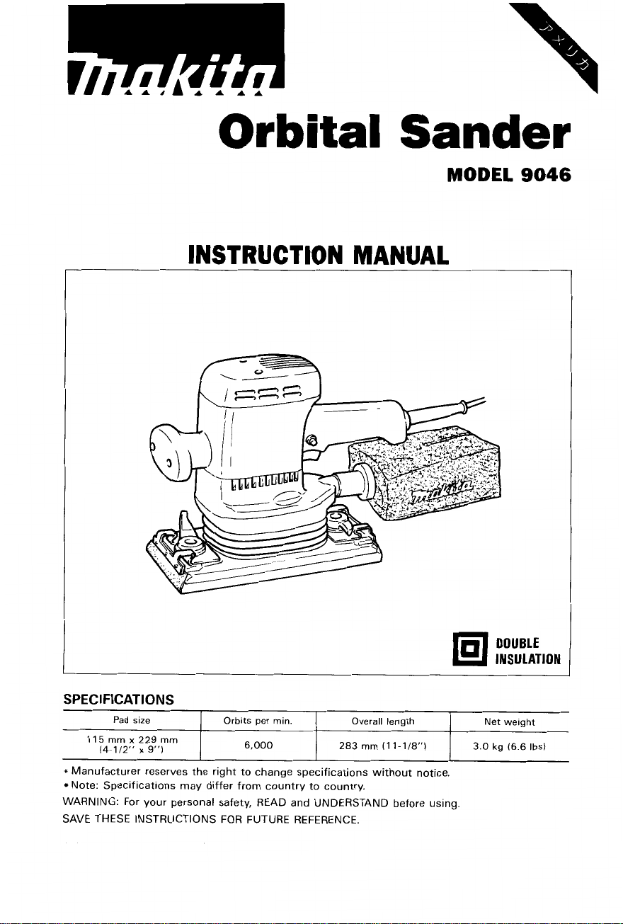
Orbital
Sander
MODEL
INSTRUCTION MANUAL
-
--
9046
SPECIFICATIONS
Pad size
115
mm
x
229 mm
(4-1/2”
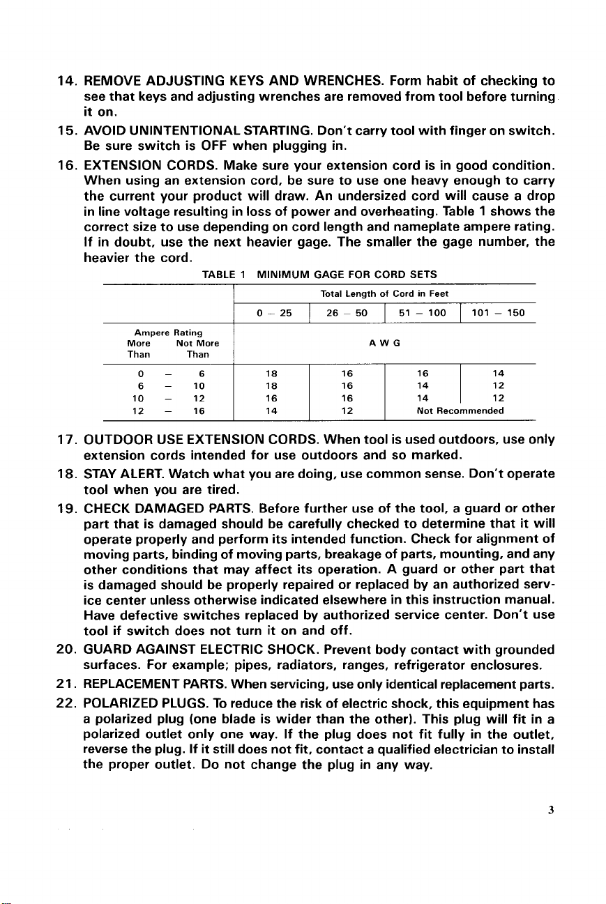
x
9”)
*
Manufacturer reserves the right to change specifications without notice.
Note: Specifications may differ from country to country.
WARNING: For your personal safety, READ and UNDERSTAND before using.
SAVE THESE INSTRUCTIONS FOR FUTURE REFERENCE.
Orbits per min. Overall length Net weight
I
6,000
283
mm
(1
I
1-1/8”)
I
3.0
kg
(6.6
Ibs)
IMPORTANT
SAFETY INSTRUCTIONS
(For
All
Tools)
WARNING:
PRECAUTIONS SHOULD ALWAYS
WHEN USING ELECTRIC TOOLS, BASIC SAFETY
BE
FOLLOWED TO REDUCE
THE RISK OF FIRE, ELECTRIC SHOCK, AND PERSONAL
INJURY, INCLUDING THE FOLLOWING:
.
READ ALL INSTRUCTIONS.
KEEP WORK AREA CLEAN. Cluttered areas and benches invite injuries.
1.
CONSIDER WORK AREA ENVIRONMENT. Don't use power tools
2.
lit.
or wet locations. Keep work area well
Don't use tool
KEEP CHILDREN AWAY. All visitors should be kept away from work area.
3.
Don't let visitors contact tool or extension cord.
STORE IDLE TOOLS. When not in use, tools should be stored
4.
or
locked-up place - out of reach of children.
DON'T FORCE TOOL.
5.
it
was intended.
USE RIGHT
6.
heavy-duty tool. Don't use tool for purpose not intended; for example, don't
use circular saw for cutting tree limbs or logs.
DRESS PROPERLY. Don't wear loose clothing or jewelry. They can be caught
7.
in
moving parts. Rubber gloves and non-skid footwear are recommended
when working outdoors. Wear protective hair covering to contain long hair.
USE SAFETY GLASSES. Also use face or dust mask
8.
dusty.
DON'T ABUSE CORD. Never carry
9.
receptacle. Keep cord from heat, oil, and sharp edges.
SECURE WORK. Use clamps or a vise to hold work.
IO.
your hand and
DON'T OVERREACH. Keep proper footing and balance at all times.
11.
MAINTAIN TOOLS WITH CARE. Keep tools sharp and clean for better and
12.
safer performance. Follow instructions for lubricating and changing accessories. Inspect tool cords periodically and
rized service facility. Inspect extension cords periodically and replace
damaged. Keep handles dry, clean, and free from oil and grease.
DISCONNECT TOOLS. When not
13.
ing
accessories, such as blades, bits, cutters.
in
presence of flammable liquids or gases.
It
will do the job better and safer at the rate for which
TOOL.
Don't force small tool
tool
it
frees both hands to operate tool.
in
Don't expose power tools to rain.
in
dry, and
or
attachment to do the job of a
if
cutting operation is
by cord or yank
if
damaged, have repaired by autho-
use, before servicing, and when chang-
it
to disconnect from
It's
safer than using
in
damp
high
if
2
Ampere Rating
More Not More
Than Than
0-
6
10
12
6
-
10
-
12
-
16
0
-
25
18 16
18 16
16 16 14 12
14 12
26 ~ 50 51 - 100 101 - 150
AWG
;:
Not Recommended
1
14
12
3
VOLTAGE WARNING: Before connecting the tool to a power source (receptacle,
outlet, etc.) be sure the voltage supplied is the same as that specified on the
nameplate of the tool.
for the tool can result
the tool.
voltage less than the nameplate rating is harmful to the motor.
If
in doubt,
A
power source with voltage greater than that specified
in
SERIOUS INJURY to the user - as well as damage to
DO
NOT PLUG IN THE
TOOL.
Using a power source
with
ADDITIONAL SAFETY RULES
1.
Hold the tool firmly.
2.
Do
not leave the tool running. Operate the tool only when hand-held.
3.
This tool has not been waterproofed,
surface.
so
do not use water on the workpiece
SAVE THESE INSTRUCTIONS.
4

Installing or removing the abrasive paper
CAUTION
Always be sure that the tool
:
is
switched off and unplugged before installing or removing
the paper.
When using the conventional type of abrasive paper (standard equipment)
:
Turn the clamp lever to open the clamper. Insert the paper end into the clamper, aligning
the holes in the paper with those in the pad. Then return the clamp lever to the original
position to secure the paper. Repeat the same process for the other end of the tool, main-
taining the proper paper tension.
1-
Conventional type
of
abrasive paper
When using the Velcro type of abrasive
paper (optional accessory)
Remove
all
dirt or foreign matter from the
:
pad. Attach the paper to the pad, aligning
the holes in the paper with those in the
pad.
CAUTION
:
Always use Velcro type of abrasive papers.
Never use pressure-sensitive abrasive paper.

Dust bag
To
install the dust bag, align the D mark
on the bag's entry port with the
on the dust spout of the tool and fit the
entry port onto the dust spout. Then turn
the dust bag clockwise to secure
place. For the best results, empty the dust
bag when
move the dust bag, follow the installation
procedures in reverse.
it
becomes about half full.
0
mark
it
To
in
re-
I
0
mark
7
D
mark
1
Dust bag
I
NOTE
:
If you connect a Makita dust collector/vacuum cleaner to your sander, more efficient and
cleaner operations can be performed.
Switch action
To start the tool, simply pull the trigger.
Release
operation, pull the trigger and then push in
the lock button. To stop the tool from the
locked position, pull the trigger fully, then
release
CAUTION
Before plugging in the tool, always check
to
perly and returns to the "OFF" position
when released.
Front grip
The front grip position can be changed in
90'
rotate
the trigger to stop. For continuous
it.
:
see
that the switch trigger actuates pro-
increments. Pull the front grip and
it
to the desired position.
Dust spout
tl
'igger
6

Operation
it
Turn the tool on and wait until
attains
full speed. Then gently place the tool on
the workpiece surface. Keep the base flush
with the workpiece
at
all times. Apply
slight pressure only. Excessive pressure
may damage the paper and shorten
tool
life.
CAUTION
:
Never run the tool without paper. You may seriously damage the pad.
MAINTENANCE
CAUTION
Always be sure that the tool
inspection or maintenance.
To maintain product SAFETY and RELIABILITY, repairs, carbon brush inspection and
replacement, any other maintenance or ajustement should be performed by Makita
Authorized or Factory Service Centers, always using Makita replacement parts.
:
is
switched off and unplugged before attempting to perform

ACCESSORIES
CAUTIO
N
These accessories or attachments are recommended for use with your Makita tool specified in this
manual. The use of any other accessories or attachments might present a risk of injury
The accessories or attachments should be used only in the proper and intended manner.
:
Abrasive paper
(with pre-punched holes)
5
mm
11
Velcro type abrasive paper
(with pre-punched holes) Part
11
(4-1/2”) x 280
5
mm
(4-1/2”) x 232
mm
mm
(1
1”)
(9-1/8“)
A-14102
A-14118
A-14124
A-14152 #lo0 Medium
A-14168 #120 Medium
A-14174
A-14180
A-14196
I
#150 I Fine
I
#180 I Fine
#240 Fine 10
No.
Grit
#150 Fine
#180
I
Fine 5
1
#240 I Fine
to
persons.
I
10
I
10
5
Joint
25
(for
connecting to Model 431)
Part
No.
192349-3
8

ORBITAL SANDER
Model
9046
Nov.-O1-'94
EN
Note: The switch, noise suppressor and other part configurations
may differ from country to country.
9

MODEL 9046 May-24-'95
'AN',"
A,,,
MACHINE
12
21
32
41
52
62
11
81
91
1
10
1
11
I2
1
1
13
14
1
15
1
16
1
11
1
18
1
19
1
20
1
21
1
22
4
23
1
24
1
25
1
26
1
27
1
28
3
1
29
1
30
31
2
32
1
1
33
34
1
35
1
Note
The
switch
DESCRIPTION
Tapping
screw 4x18
Top Cover
Tapping
Screw
Grip
Carbon
Brush
Grip
Compression
Flat
Tapping
Makita
Ball
lnsulafion
ARMATURE ASSEMBLY
IWilh
Fan
Ball Bedriny 6201DDW
Flat
Scroll
Earth
I
an
Gear
Tdppinq
Needle
Helcal
Ball
Crank
Bcdrinq
Tdppinq
Dust
Bdfllr:
Ta~ping
FlLld
support ComplP,'.
Motor
C,l,d
and
4x18
Cover
Brush
Holder
Base
Sprinq
5
Screw
608LB
Washer
12. 13
Scr~w
39
6203DDW
Refalncr
Screw
Compleir~
S~rew
24
PT 5x20
15
Flange
810
24
CT 4x12
Flange
Washer
Label
Bearing
ltPm
60
Wazhcr 26
Housing
Plats
68
Box
Bearing
Gear
Bedrirlq
Shdll
Bay
Plale
Hoiisiiig
other part bpc~111~alions
&
161
PT
4x20
PT 5x45
rnay
differ from
country
MACHINE
__
36
37
38
40
41
42
43
44
45
46
41
48
49
50
51
52
53
54
55
56
57
58
59
60
61
62
63
64
65
66
67
68
69
70
71
lo
country
$$&,
DESCRIPTION
1
Cord Guard
1
Strain
2
Tapping
I
Switch
1
Name
4
Tapping
1
Handle
Tapping
2
1
Packing
1
Scroll
2
lapping
1
Rubber
1
Plate
2
Tapping
3
Tapping
2
Flat
2
Clamp
2
Sleeve
2
Paper
4
P,"
1
Bala"Cer
1
Hex
1
0
1
Under
1
Pad
Tapping
4
Tapping
4
1
Base
1
Flat
1
Ball
1
Ring
1
Ring 15
1
Ball Bearing 6002DDW
1
Bearing
Tapping
4
Relief
Screw
Plate
Screw
Cover
Screw
4x18
cover
Screw
Sleeve
Screw
Screw
Washer
4
Lever
4
Clamp
Complele
3
Socket
Head
Ring
75
Cover
Screw
Bind CT 4x12
Screw
Bind CT 4x1 2
Washer
26
Bearing 6002DDW
19
Retainer
Screw
Flange PT 4x 12
4x18
Bind
CT
5x90
Flange
PI 4x1 2
Bind CT 4x20
CT 4x12
Boll
M5x16
24
US
10

MAKITA LIMITED ONE YEAR WARRANTY
Warranty
Every Makita
be free of defects from workmanship and materials for the period
original purchase. Should any trouble develop during this one-year period, return the COMPLETE
tool,
the trouble is caused by defective workmanship or material, Makita will repair (or at our option,
replace) without charge.
This Warranty does not apply where:
a
repairs have been made or attempted by others:
a
repain are required because of normal wear and tear:
The
a
alterations have been made
IN NO EVENT SHALL MAKITA BE LIABLE FOR ANY INDIRECT, INCIDENTAL OR CONSEQUENTIAL DAMAGES FROM THE SALE OR USE OF THE PRODUCT. THIS DISCLAIMER
APPLIES BOTH DURING AND AFTER THE TERM OF THIS WARRANTY.
MAKITA DISCLAIMS LIABILITY FOR ANY IMPLIED WARRANTIFS, INCLUDING IMPLIED
WARRANTIES OF “MERCHANTABILITY” AND “FITNESS FOR A SPFCIFIC PURPOSE,”
AFTER THE ONE-YEAR TERM
This Warranty gives you specific legal
state to state. Some states do not allow the exclusion or limitation
damages,
limitation
tool
is thoroughly inspected and tested before leaving the factory.
freight prepaid, to one of Makita’s Factory or Authorized Service Centers. If inspection shows
tool
has
been
abused, misused
so
the above limitation or exclusion may not apply
on
how long an implied warranty
or
improperly maintained;
to
the
tool.
OF
THIS WARRANTY.
rights,
u
Policy
It
of
ONE YEAR from the date of
and you may also have other rights which vary from
lasts,
so
the above Limitation may not apply
of
incidental or consequential
to
you. Some states do not allow
is warranted
to
you.
to
Makita Corporation
3-11
-8,
Sumiyoshi-cho,
446
883989
Japan
-
067
Anjo, Aichi
PRINTED IN JAPAN
1995 - 7
-
N
 Loading...