

Page 1

MODEL
INSTRUCTION MANUAL
Finishing Sander & Standard Equipment
904SN
0
Dust
@Tool
@Abra
Specifications
I
Continuous
size
Pad
114mmx234mm
(4.112") x (9-114")
*
Manufacturer reserves
*
Note: Specifications of parts and accessories may vary from country to country.
the
rating ~
,
(Input)
I
410w
i
right to change specifications of parts and accessories without notice
No
speed
10,000
O1min.
Overall
1
length
268
1
(10-518")
1
mm
1
w!i:kt
2.8
(6.2
kg
Ibsl
~
I
1
Power
2.5m
(8.2
ft.)
Page 2
IMPORTANT SAFETY INSTRUCTIONS
WARNING: When using electric tools, basic safety precautions should always be followed
to reduce the risk of fire, electric shock, and personal injury, including the following:
READ ALL INSTRUCTIONS.
1.
KEEP WORK AREA CLEAN. Cluttered areas and benches invite injuries.
2.
CONSIDER WORK AREA ENVIRONMENT. Don't
lit.
locations. Keep work area well
in presence of flammable liquids or
3. KEEP CHILDREN AWAY. All visitors should be kept away from work area. Don't
let
visitors contact tool or extension cord.
4. STORE IDLE TOOLS. When not in use, tools should be stored in dry, and high or
locked-up place
5.
DON'T FORCE TOOL.
was intended.
6. USE RIGHT TOOL. Don't force small tool
duty tool. Don't use tool for purpose not intended.
7. DRESS PROPERLY.
moving parts. Rubber gloves and non-skid footwear are recommended when working
outdoors. Wear protective hair covering to contain long hair.
8.
USE SAFETY GLASSES. Also use face or dust mask if cutting operation
9.
DON'T ABUSE CORD. Never carry tool by cord or yank
ceptacle. Keep cord from heat, oil, and sharp edges.
10. SECURE WORK.
and
it
frees both hands
11.
DON'T OVERREACH. Keep proper footing and balance
12.
MAINTAIN TOOLS WITH CARE. Keep tools sharp and clean for better and safer
performance. Follow instructions for lubricating and charging accessories.
tool cords periodically and if damaged, have repaired by authorized service facility.
Keep handles dry, clean, and free from oil and grease.
13. DISCONNECT TOOLS. When not in use, before servicing, and when changing accessories, such
14. REMOVE ADJUSTING KEYS AND WRENCHES. Form habit of checking to
that keys and adjusting wrenches are removed from tool before turning
15.
AVOID UNINTENTIONAL STARTING. Don't carry plugged-in tool with finger on
switch. Be sure switch
16. OUTDOOR USE EXTENTION CORDS. When tool
sion cords intended for use outdoors and
17. STAY ALERT.
when you are tired.
-
out of reach of children.
It
will do the job better and safer
Don't wear
Use clamps or
to
operate tool.
as
blades, bits, cutters.
is
OFF when plugging in.
Watch what you are doing, use common sense. Don't operate tool
Don't expose power tools to rain. Don't use tool
gases.
or
loose
clothing or jewelry. They can be caught in
a
vise
to hold work.
so
marked.
use
power tools in damp or wet
at
the rate for which
attachment to do the job of a heavy-
is
dusty.
it
to disconnect from re-
It's
safer than using your hand
at
all
times.
Inspect
see
it
on.
is
used outdoors, use only exten-
it
2
Page 3
18.
CHECK DAMAGED PARTS. Before further use of the tool, a guard or other part
that
is
damaged should be carefully checked to determine that
ly
and perform
its
intended function. Check for alignment of moving parts, binding
it
will operate proper-
of moving parts, breakage of parts, mounting, and other conditions that may affect
its
operation. A guard or other part that
replaced
by
an authorized service center unless otherwise indicated elsewhere in this
is
damaged should be properly repaired or
instruction manual. Have defective switches replaced by authorized service center.
Don't use tool if switch does not turn
19.
GUARD AGAINST ELECTRIC SHOCK.
on and
off.
Prevent
body
contact
with
grounded
it
faces. For example; pipes, radiators, ranges, refrigerator enclosures.
20.
REPLACEMENT PARTS. When servicing, use only identical replacement parts.
SAVE THESE INSTRUCTIONS.
sur-
VOLTAGE WARNING: Before connecting the tool to a power source (receptacle. outlet, etc.1 be sure
the voltage supplied
voltage greater than that specified for the tool can result in
damage to the tool.
less
than the nameplate rating
How
to
use
is
the same as that specified on the nameplate of the tool. A power source with
If in doubt,
DO
NOT
is
harmful to the motor.
PLUG
IN
SERIOUS
THE
TOOL. Using a power source with voltage
INJURY to the user - as
well
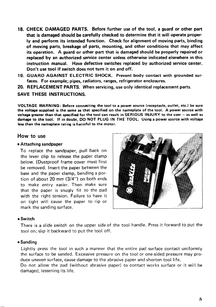
Attaching sandpaper
To replace the sandpaper, pull back
on
the lever clip to release the paper clamp
below. (Dustproof frame cover must first
be removed. Insert the paper between the
a
base and the paper clamp, bending
tion
of about
20
mm
(3/4")
on
por-
both ends
to make entry easier. Then make sure
is
that the paper
snugly fit
with the right tension. Failure to have
on tight will cause the paper
to
to
the pad
it
rip or
mark the sanding surface.
Switch
There
is
a
tool
slide switch on the upper side of the tool handle. Press
on;
slip
it
backward to put the tool off.
it
forward to put the
Sanding
a
Lightly press the tool in such
manner that the entire pad surface contact uniformly
the surface to be sanded. Excessive pressure on the tool or one-sided pressure may produce uneven surface, cause damage to the abrasive paper and shorten tool life.
it
Do not allow the pad (without abrasive paper) to contact works surface or
its
damaged, lessening
life.
will be
as
3
Page 4

0
Dust bag attachment
To
install the dust bag, fit the bag's
entry port onto the dust chute on the
see
right side of the sander, then
that the
small hole on the port fits over the pin
protruding from the chute by turning left
or right.
When removing the dust bag, turn the bag
to the left
to
slip the hole off the pin,
then simply pull off the dust bag.
Removing the frame cover
Remove from either the front or back
shown, when taking off the frame cover.
0
Regular emptying
of
dust bag
Regular emptying of the dust bag insures
the maximum suction force.
A
full bag
makes for ineffective dust collection.
as
0
Operation with coolant
a
This tool can be used to sand with waterproof paper and
coolant, but coolant should
never be allowed to enter the motor area. To use coolant, first remove the dust bag and
Do
a
clean off any dust adhering to the tool.
dry run for 2 or 3 minutes with the tool
held off the surface in order to remove dust adhering to the dust chute area. Then use
only enough coolant to
give
good operation
as
excessive coolant can easily be splashed
into the motor and markedly shorten motor life. Coolant may also bridge parts which
a
could result in
commercial
228 mm
be
4
(9")
used by cutting
shock hazard.
abrasive paper of the
x 280 mm
it
in half.
(1
1-1/16"1
size
may
..
..
..
-
.-
.. .
,.
.:_
'280
mm ( 11-1/16")
.
..
...
_.
.-.
..
..
.
..
..
Page 5

Maintenance
0
Carbon brushes
Replace carbon brushes when they wear
to
about
6
mm
down
(1/4")
or spark-
ing will occur. Both brushes should be
at
changed
the same time.
Optional accessories
CAUTION:
0
Abrasive papers
#
The
use
of
any other accessories not specified
60
I
742501-9
1
Coarse
I
in
this
manual might
be
hazardous.
#180
742505-1
5
Page 6

FINISHING
Model
9045N
SANDER
6
Page 7

'ibM
61
71
81
91
10
1
1
12
2
15
2
16
1
17
1
18
1
19
1
20
21
2
22
1
1
23
1
24
1
25
1
26
1
27
1
28
1
29
2
30
-
DESCRIPTION
Rivet 0-5
Name Plate
P.
H
Screw
M5x35
Carbon Brush
Brush
Holder
Slider
Rubber Washer
Switch
FIELD ASSEMBLY
IWith Garter Spring
Baffle Plate
separate
Motor Housing
IWith Brush
H Bolt
Rubber Pin 4
P
CORD ASSEMBLY
(Assembled Cord. Plug
Cord
Strain
P.
P.
stopper
Frame
(With Needle Bearing 8101
Frame Cover
Poly V-Belt 3-250
V-Pulley 3-26
Spindle
Key 4
Steel
Cap
Cover
Holder
M5x40 (With Washer)
H.
Screw
M4x12 (With Washer1
Guard
Relief
H.
Screw
M4xl8 IWith Washer1
H. Screw
M4x10 (With Washer)
Band
x
21
x
2
&
&
S.
Screw
Cord Guard)
M5x8
':EM
,,!&
DESCRIPTION
MACHINE
31
32
33
34
35
36
37
38
39
40
41
42
x
2)
43 44
45
46
47 48
49
50
51
52
53
ACCESS0
403
;;;
P.
2
H.
Screw
M14x25
Rubber
1
2
1
1
1
1
1
1
2
2
2
2
1
1
1
1
1
1
1
1
1
1
R
I
ES
1 AbrariwPaper 114-150
~
;
Sleeve
P
H.
Screw
M4x30 (With Warherl
Handle
Cover
Rubber Pin
6
Balance
Weight
Bare
(With Sponge Rubber)
Ball Bearing 6002LLB
Bearing Retainer 40
C.
H.
Screw
H.
Screw
Nut M4
Bearing 6003DDU
Washer
26
H.
Screw
70
Bag
F.3Ste"W
M4x12
M4x10
M5x12
C.
Push Button
H.
Ball
F.
F. Washer 7
C.
Bearing Retainer
(With Sponge Rubber)
Ball Bearing M)BLB
Insulation Washer
ARMATURE ASSEMBLY
lAwmbled Items 49
Fan
Ball Bearing 6200LLB
1
Dust
-
531
7
Page 8

P
Every Makita tool is thoroughly inspected and tested before leaving the factory. It is warranted to
be free of defects from workmanship and materials for the period of ONE YEAR from the date of
original purchase. Should any trouble develop during this one-year period, return the COMPLETE
tool, freight prepaid, to one of Makita’s Factory or Authorized Service Centers. If inspection shows
the trouble is caused by defective workmanship
replace) without charge.
This Warranty does not apply where:
repairs have been made or attempted by others:
0
repairs are required because
The tool has been abused, misused or improperly maintained;
alterations have been made to the tool.
IN NO EVENT SHALL MAKITA BE LIABLE FOR ANY INDIRECT, INCIDENTAL OR CONSEQUENTIAL DAMAGES FROM THE SALE OR USE OF THE PRODUCT. THIS DISCLAIMER
APPLIES BOTH DURING AND AFTER THE TERM OF THIS WARRANTY.
MAKITA DISCLAIMS LIABILITY FOR ANY IMPLIED WARRANTIES, INCLUDING IMPLIED
WARRANTIES
AFTER THE ONE-YEAR TERM
This Warranty gives you specific legal rights, and you may also have other rights which vary from
state to state. Some states do not allow the exclusion or Limitation of incidental or consequential
damages,
limitation
.
. . . . . . . . . . . .
. . . . . . . -.
. ._
__. . . -.
MAKITA LIMITED ONE YEAR WARRANTY
Warranty Policy
or material, Makita
of
nonnal wear and tear:
OF
“MERCHANTABILITY” AND “FITNESS FOR A SPECIFIC PURPOSE,
so
the above limitation or exclusion may not apply to you. Some states
on
how long an implied warranty lasts,
OF
THIS WARRANTY.
so
the above limitation may not apply to
will
repair (or at our option,
do
not allow
you.
-.
-
___
11-8.3-chome, Sumiyorhi-cho. Anjo, Aichi
FlArtkrir-,Ltd.
883130-062
B
446,
Japan
PRINTED IN JAPAN
1985-6-N
 Loading...