

Makita 8434D, 8444D, 8414D User Manual
Cordless Percussion-Driver Drill
GB
Instruction Manual
Perceuse percussion-visseuse sans fil
F
Akku-Schlagbohrschrauber
D
Trapano avvitatore percussione a batteria
I
Accu slagboor/schroevedraaier
NL
Taladro atornillador con percusión a batería
E
Berbequim de percussão a bateria
P
Akku-slagboremaskine/skruemaskine
DK
Sladdlös slagborr/skruvmaskin
S
Batteridrevet slagbor med skrutrekker
N
Akkukäyttöinen iskupora/ruuvinväännin
SF
Ασύρµατο κρουστικ κατσαβίδι-τρυπάνι Οδηγίες χρήσεως
GR
Manuel d’instructions
Betriebsanleitung
Istruzioni per l’uso
Gebruiksaanwijzing
Manual de instrucciones
Manual de instruções
Brugsanvisning
Bruksanvisning
Bruksanvisning
Käyttöohje
8414D
8434D
8444D
1
3
2
12
A
4
B
5
34
8
6
7
9
56
10
11
14
15
13
12
78
2
16
18
19
17
910
20
11 12
21
13 14
22
23
3

ENGLISH
Explanation of general view
1Button
2 Battery cartridge
3 Switch trigger
4 Reversing switch lever
5 Speed change lever
6 Action mode change lever
7Arrow
8 Adjusting ring
SPECIFICATIONS
Model 8414D 8434D 8444D
Capacities
Concrete............................................... 13 mm 14 mm 16 mm
Steel ..................................................... 13 mm 13 mm 13 mm
Wood.................................................... 45 mm 50 mm 65 mm
Wood screw.......................................... 6 mm x 75 mm 6 mm x 75 mm 10 mm x 89 mm
Machine screw ..................................... 6 mm 6 mm 6 mm
No load speed (min
High (3)................................................. 0 – 1,600 0 – 1,700 0 – 1,700
Medium (2) ........................................... 0 – 550 0 – 600 0 – 600
Low (1) ................................................. 0 – 300 0 – 300 0 – 300
Blows per minute (min
High (3)................................................. 0 –24,000 0 – 25,500 0– 25,500
Medium (2) ........................................... 0 – 8,250 0 – 9,000 0 – 9,000
Low (1) ................................................. 0 – 4,500 0 – 4,500 0 – 4,500
Overall length .......................................... 259 mm 259 mm 259 mm
Net weight ............................................... 2.4 kg 2.5 kg 2.7 kg
Rated voltage .......................................... D. C. 12 V D. C. 14.4 V D. C. 18 V
-1
)
-1
)
9 Graduations
10 Steel band
11 Grip base
12 Side grip
13 Protrusion
14 Groove
15 Sleeve
16 Bit
17 Bit holder
18 Depth rod
19 Clamp screw
20 Blow-out bulb
21 Limit mark
22 Brush holder cap
23 Screwdriver
• Due to our continuing program of research and devel-
opment, the specifications herein are subject to change
without notice.
• Note: Specifications may differ from country to country.
Intended use
The tool is intended for impact drilling in brick, concrete
and stone as well as for drilling without impact in wood,
metal, ceramic and plastic.
Safety hints
For your own safety, please refer to the enclosed safety
instructions.
ADDITIONAL SAFETY RULES FOR POWER
TOOL
DO NOT let comfort or familiarity with product
(gained from repeated use) replace strict adherence
to hammer drill safety rules. If you use this power
tool unsafely or incorrectly, you can suffer serious
personal injury.
1. Wear ear protectors with impact drills. Exposure
to noise can cause hearing loss.
2. Use auxiliary handles supplied with the tool.
Loss of control can cause personal injury.
3. Hold tools by insulated gripping surfaces when
performing an operation where the cutting tool
may contact hidden wiring or its own cord. Contact with a “live” wire will make exposed metal
parts of the tool “live” and shock the operator.
4. Always be sure you have a firm footing.
Be sure no one is below when using the tool in
high locations.
GEB003-1
4
5. Hold the tool firmly with both hands.
6. Keep hands away from rotating parts.
7. Do not leave the tool running. Operate the tool
only when hand-held.
8. Do not touch the bit or the workpiece immediately after operation; they may be extremely hot
and could burn your skin.
9. Some material contains chemicals which may be
toxic. Take caution to prevent dust inhalation
and skin contact. Follow material supplier safety
data.
SAVE THESE INSTRUCTIONS.
IMPORTANT SAFETY INSTRUCTIONS FOR
CHARGER & BATTERY CARTRIDGE
1. Before using battery cartridge, read all instructions and cautionary markings on (1) battery
charger, (2) battery, and (3) product using battery.
2. Do not disassemble battery cartridge.
3. If operating time has become excessively
shorter, stop operating immediately. It may
result in a risk of overheating, possible burns
and even an explosion.
4. If electrolyte gets into your eyes, rinse them out
with clear water and seek medical attention right
away. It may result in loss of your eyesight.
5. Always cover the battery terminals with the battery cover when the battery cartridge is not
used.
6. Do not short the battery cartridge:
ENC004-1

(1) Do not touch the terminals with any conduc-
tive material.
(2) Avoid storing battery cartridge in a container
with other metal objects such as nails, coins,
etc.
(3) Do not expose battery cartridge to water or
rain.
A battery short can cause a large current flow,
overheating, possible burns and even a breakdown.
7. Do not store the tool and battery cartridge in
locations where the temperature may reach or
exceed 50°C (122°F).
8. Do not incinerate the battery cartridge even if it
is severely damaged or is completely worn out.
The battery cartridge can explode in a fire.
9. Be careful not to drop or strike battery.
SAVE THESE INSTRUCTIONS.
Tips for maintaining maximum battery life
1. Charge the battery cartridge before completely
discharged.
Always stop tool operation and charge the battery cartridge when you notice less tool power.
2. Never recharge a fully charged battery cartridge.
Overcharging shortens the battery service life.
3. Charge the battery cartridge with room temperature at 10°C – 40°C (50°F – 104°F). Let a hot battery cartridge cool down before charging it.
4. Charge the Nickel Metal Hydride battery cartridge when you do not use it for more than six
months.
FUNCTIONAL DESCRIPTION
CAUTION:
• Always be sure that the tool is switched off and the bat-
tery cartridge is removed before adjusting or checking
function on the tool.
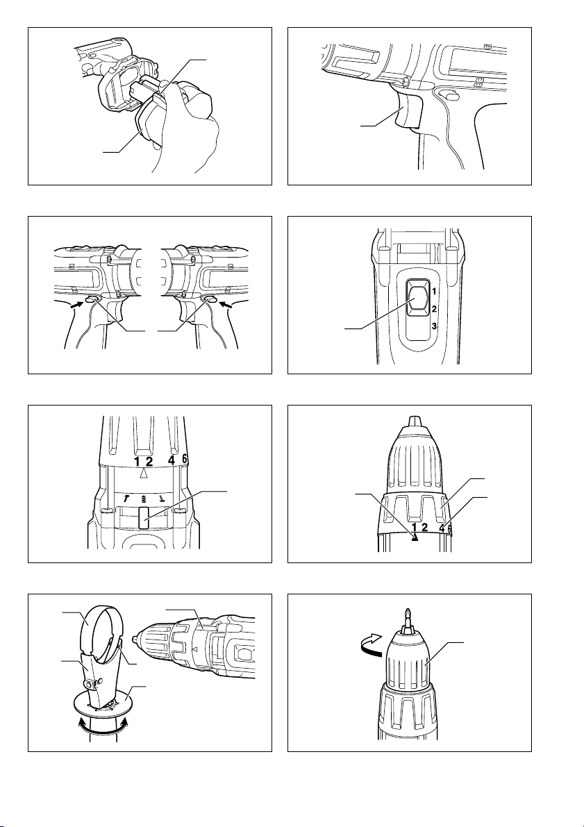
Installing or removing battery cartridge (Fig. 1)
• Always switch off the tool before insertion or removal of
the battery cartridge.
• To remove the battery cartridge, withdraw it from the
tool while pressing the buttons on both sides of the cartridge.
• To insert the battery cartridge, align the tongue on the
battery cartridge with the groove in the housing and slip
it into place. Always insert it all the way until it locks in
place with a little click. If not, it may accidentally fall out
of the tool, causing injury to you or someone around
you.
• Do not use force when inserting the battery cartridge. If
the cartridge does not slide in easily, it is not being
inserted correctly.
Switch action (Fig. 2)
CAUTION:
• Before inserting the battery cartridge into the tool,
always check to see that the switch trigger actuates
properly and returns to the “OFF” position when
released.
To start the tool, simply pull the switch trigger. Tool speed
is increased by increasing pressure on the switch trigger.
Release the switch trigger to stop.
Reversing switch action (Fig. 3)
This tool has a reversing switch to change the direction of
rotation. Depress the reversing switch lever from the “A”
side for clockwise rotation or from the “B” side for counterclockwise rotation.
When the reversing switch lever is in the neutral position,
the switch trigger cannot be pulled.
CAUTION:
• Always check the direction of rotation before operation.
• Use the reversing switch only after the tool comes to a
complete stop. Changing the direction of rotation
before the tool stops may damage the tool.
• When not operating the tool, always set the reversing
switch lever to the neutral position.
Speed change (Fig. 4)
This tool has a three-gear speed change lever. To
change the speed, first switch off the tool and then slide
the speed change lever to the “1” position for low speed,
“2” position for medium speed or “3” position for high
speed. Be sure that the speed change lever is set to the
correct position before operation. Use the right speed for
your job.
NOTE:
When changing the position from “1” to “3” or from “3” to
“1”, it may be a little difficult to slide the speed change
lever. At this time, switch on and run the tool for a second
at the “2” position, then stop the tool and slide to your
desired position.
CAUTION:
• Always set the speed change lever fully to the correct
position. If you operate the tool with the speed change
lever positioned halfway between the “1” position, “2”
position and “3” position, the tool may be damaged.
• Do not use the speed change lever while the tool is running. The tool may be damaged.
Selecting the action mode (Fig. 5)
This tool employs an action mode changing lever. Select
one of the three modes suitable for your work needs by
using this lever.
For rotation only, slide the lever so that it points toward
the m mark on the tool body.
For rotation with hammering, slide the lever so that it
points toward the mark on the tool body.
For rotation with clutch, slide the lever so that it points
toward the mark on the tool body.
NOTE:
When changing the position from to m, it may be a little difficult to slide the mode change lever. At this time,
switch on and run the tool for a second at the position,
then stop the tool and slide to your desired position.
CAUTION:
Always set the lever correctly to your desired mode mark.
If you operate the tool with the lever positioned halfway
between the mode marks, the tool may be damaged.
Adjusting the fastening torque (Fig. 6)
The fastening torque can be adjusted in 16 steps by turning the adjusting ring so that its graduations are aligned
with the arrow on the tool body. The fastening torque is
minimum when the number 1 is aligned with the arrow,
and maximum when the number 16 is aligned with the
arrow.
Before actual operation, drive a trial screw into your
material or a piece of duplicate material to determine
which torque level is required for a particular application.
5

ASSEMBLY
CAUTION:
• Always be sure that the tool is switched off and the battery cartridge is removed before carrying out any work
on the tool.
Installing side grip (auxiliary handle) (Fig. 7)
Always use the side grip to ensure operating safety.
Install the side grip so that the protrusions on the grip
base fit in between the grooves on the barrel. Then
tighten the grip by turning clockwise.
Installing or removing driver bit or drill bit
Turn the sleeve counterclockwise to open the chuck jaws.
Place the bit in the chuck as far as it will go. Turn the
sleeve clockwise to tighten the chuck. To remove the bit,
turn the sleeve counterclockwise. (Fig. 8)
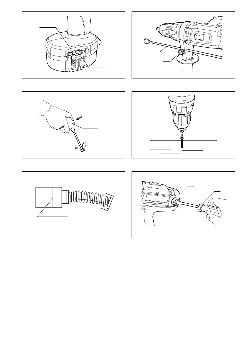
When not using the driver bit, keep it in the bit holders.
Bits 45 mm long can be kept there. (Fig. 9)
Adjustable depth rod (Fig. 10)
The adjustable depth rod is used to drill holes of uniform
depth. Loosen the clamp screw, set to desired position,
then tighten the clamp screw.
OPERATION
Hammer drilling operation
CAUTION:
• There is a tremendous and sudden twisting force
exerted on the tool/bit at the time of hole breakthrough, when the hole becomes clogged with chips
and particles, or when striking reinforcing rods embedded in the concrete. Always use the side grip (auxiliary
handle) and firmly hold the tool by both side grip and
switch handle during operations. Failure to do so may
result in the loss of control of the tool and potentially
severe injury.
First, slide the action mode change lever so that it points
to the marking. The adjusting ring can be aligned in
any torque levels for this operation.
Be sure to use a tungsten-carbide tipped bit.
Position the bit at the desired location for the hole, then
pull the switch trigger. Do not force the tool. Light pressure gives best results. Keep the tool in position and prevent it from slipping away from the hole.
Do not apply more pressure when the hole becomes
clogged with chips or particles. Instead, run the tool at an
idle, then remove the bit partially from the hole. By
repeating this several times, the hole will be cleaned out
and normal drilling may be resumed.
Blow-out bulb (optional accessory) (Fig. 11)
After drilling the hole, use the blow-out bulb to clean the
dust out of the hole.
Screwdriving operation (Fig. 12)
First, slide the action mode change lever so that it points
to the marking. Adjust the adjusting ring to the proper
torque level for your work. Then proceed as follows.
Place the point of the driver bit in the screw head and
apply pressure to the tool. Start the tool slowly and then
increase the speed gradually. Release the switch trigger
as soon as the clutch cuts in.
NOTE:
• Make sure that the driver bit is inserted straight in the
screw head, or the screw and/or bit may be damaged.
• When driving wood screws, predrill pilot holes to make
driving easier and to prevent splitting of the workpiece.
See the chart.
Nominal diameter of
wood screw (mm)
3.1 2.0 – 2.2
3.5 2.2 – 2.5
3.8 2.5 – 2.8
4.5 2.9 – 3.2
4.8 3.1 – 3.4
5.1 3.3 – 3.6
5.5 3.6 – 3.9
5.8 4.0 – 4.2
6.1 4.2 – 4.4
NOTE:
• If the tool is operated continuously until the battery cartridge has discharged, allow the tool to rest for 15 minutes before proceeding with a fresh battery.
Recommended size of
pilot hole (mm)
Drilling operation
CAUTION:
• Pressing excessively on the tool will not speed up the
drilling. In fact, this excessive pressure will only serve
to damage the tip of your bit, decrease the tool performance and shorten the service life of the tool.
• There is a tremendous force exerted on the tool/bit at
the time of hole break through. Hold the tool firmly and
exert care when the bit begins to break through the
workpiece.
• A stuck bit can be removed simply by setting the
reversing switch to reverse rotation in order to back out.
However, the tool may back out abruptly if you do not
hold it firmly.
• Always secure small workpieces in a vise or similar
hold-down device.
• If the tool is operated continuously until the battery cartridge has discharged, allow the tool to rest for 15 minutes before proceeding with a fresh battery.
First, slide the action mode change lever so that it points
to the m marking. The adjusting ring can be aligned in
any torque levels for this operation. Then proceed as follows.
Drilling in wood
When drilling in wood, the best results are obtained with
wood drills equipped with a guide screw. The guide
screw makes drilling easier by pulling the bit into the
workpiece.
6
 Loading...