

Page 1
Cordless PercussionDriver Drill
Equipped with Electric Brake
MODEL 8413D
MODEL 8433D
MODEL 8443D
INSTRUCTION MANUAL
WARNING:
For your personal safety, READ and UNDERSTAND before using.
SAVE THESE INSTRUCTIONS FOR FUTURE REFERENCE.
www.makitatools.com
Page 2

SPECIFICATIONS
Model 8413D 8433D 8443D
Concrete 13 mm (1/2”) 14 mm (9/16”) 16 mm (5/8”)
Steel 13 mm (1/2”) 13 mm (1/2”) 13 mm (1/2”)
Capacities
No load speed
(RPM)
Blows per minute
Overall length 267 mm (10-1/2”) 267 mm (10-1/2”) 267 mm (10-1/2”)
Net weight 2.3 kg (5.1 lbs) 2.4 kg (5.3 lbs) 2.6 kg (5.7 lbs)
Wood 30 mm (1-3/16”) 36 mm (1-7/16”) 38 mm (1-1/2”)
Wood screw
Machine screw 6 mm (1/4”) 6 mm (1/4”) 6 mm (1/4”)
High 0 - 1,300/min. 0 - 1,300/min. 0 - 1,400/min.
Low 0 - 400/min. 0 - 400/min. 0 - 450/min.
High 0 - 19,500 0 - 19,500 0 - 21,000
Low 0 - 6,000 0 - 6,000 0 - 6,750
6 mm x 75 mm
(1/4” x 3”)
6 mm x 75 mm
(1/4” x 3”)
10 mm x 90 mm
(3/8” x 3-1/2”)
Battery
Cartridge
1222
1233 50 min.
1234 60 min.
1235 70 min.
1422
1433 50 min.
1434 60 min.
1435 70 min.
1822
1833 50 min.
1834 60 min.
1835 70 min.
Vol tage
12 V
14.4 V
18 V DC1804
Battery
Charger
DC1414
Input Output Charging time
D.C.
7.2 V - 14.4 V
A. C. only
50 Hz - 60 Hz
D.C.
7.2 V - 18 V
• Manufacturer reserves the right to change specifications without notice.
• Specifications may differ from country to country.
2
45 min.
45 min.
45 min.
Page 3

GENERAL SAFETY RULES USA003-1
(FOR All BATTERY OPERATED TOOLS)
WARNING:
Read and understand all instructions. Failure to follow all
instructions listed below, may result in electric shock, fire and/or
serious personal injury.
SAVE THESE INSTRUCTIONS
Work Area
1. Keep your work area clean and well lit.
Cluttered benches and dark areas invite accidents.
2. Do not operate power tools in explosive
atmospheres, such as in the presence of
flammable liquids, gases, or dust. Powe r
tools create sparks which may ignite the dust
or fumes.
3. Keep bystanders, children, and visitors
away while operating a power tool. Distrac-
tions can cause you to lose control.
Electrical Safety
4. A battery operated tool with integral batteries or a separate battery pack must be
recharged only with the specified charger
for the battery. A charger that may be suit-
able for one type of battery may create a risk
of fire when used with another battery.
5. Use battery operated tool only with specifically designated battery pack. Use of any
other batteries may create a risk of fire.
Personal Safety
6. Stay alert, watch what you are doing, and
use common sense when operating a
power tool. Do not use tool while tired or
under the influence of drugs, alcohol, or
medication. A moment of inattention while
operating power tools may result in serious
personal injury.
7. Dress properly. Do not wear loose clothing or jewelry. Contain long hair. Keep
your hair, clothing, and gloves away from
moving parts. Loose clothes, jewelry, or long
hair can be caught in moving parts.
8. Avoid accidental starting. Be sure switch
is in the locked or off position before
inserting battery pack. Carrying tools with
your finger on the switch or inserting the battery pack into a tool with the switch on invites
accidents.
9. Remove adjusting keys or wrenches
before turning the tool on. A wrench or a
key that is left attached to a rotating part of
the tool may result in personal injury.
10. Do not overreach. Keep proper footing
and balance at all times. Proper footing and
balance enable better control of the tool in
unexpected situations.
11. Use safety equipment. Always wear eye
protection. Dust mask, non-skid safety
shoes, hard hat, or hearing protection must
be used for appropriate conditions.
3
Page 4

Tool Use and Care
12. Use clamps or other practical way to
secure and support the workpiece to a
stable platform. Holding the work by hand or
against your body is unstable and may lead
to loss of control.
13. Do not force tool. Use the correct tool for
your application. The correct tool will do the
job better and safer at the rate for which it is
designed.
14. Do not use tool if switch does not turn it
on or off. A tool that cannot be controlled
with the switch is dangerous and must be
repaired.
15. Disconnect battery pack from tool or
place the switch in the locked or off position before making any adjustments,
changing accessories, or storing the tool.
Such preventive safety measures reduce the
risk of starting the tool accidentally.
16. Store idle tools out of reach of children
and other untrained persons. Tools are
dangerous in the hands of untrained users.
17. When battery pack is not in use, keep it
away from other metal objects like: paper
clips, coins, keys, nails, screws, or other
small metal objects that can make a connection from one terminal to another.
Shorting the battery terminals together may
cause sparks, burns, or a fire.
18. Maintain tools with care. Keep cutting
tools sharp and clean. Properly maintained
tools with sharp cutting edge are less likely to
bind and are easier to control.
19. Check for misalignment or binding of
moving parts, breakage of parts, and any
other condition that may affect the tool’s
operation. If damaged, have the tool serviced before using. Many accidents are
caused by poorly maintained tools.
20. Use only accessories that are recommended by the manufacturer for your
model. Accessories that may be suitable for
one tool may create a risk of injury when
used on another tool.
SERVICE
21. Tool service must be performed only by
qualified repair personnel. Service or main-
tenance performed by unqualified personnel
may result in a risk of injury.
22. When servicing a tool, use only identical
replacement parts. Follow instructions in
the Maintenance section of this manual.
Use of unauthorized parts or failure to follow
Maintenance instructions may create a risk of
shock or injury.
SPECIFIC SAFETY RULES USB023-2
DO NOT let comfort or familiarity with product (gained from
repeated use) replace strict adherence to cordless hammer drill
safety rules. If you use this tool unsafely or incorrectly, you can
suffer serious personal injury.
1. Hold tool by insulated gripping surfaces
when performing an operation where the
cutting tool may contact hidden wiring.
Contact with a “live” wire will make exposed
metal parts of the tool “live” and shock the
operator.
4
2. Be aware that this tool is always in an
operating condition, because it does not
have to be plugged into an electrical outlet.
Page 5

3. Always be sure you have a firm footing. Be
sure no one is below when using the tool in
high locations.
4. Hold the tool firmly.
5. Keep hands away from rotating parts.
6. Do not leave the tool running. Operate the
tool only when hand-held.
7. Do not touch the bit or the workpiece
immediately after operation; they may be
extremely hot and could burn your skin.
8. Some material contains chemicals which
may be toxic. Take caution to prevent dust
inhalation and skin contact. Follow material supplier safety data.
SAVE THESE INSTRUCTIONS
WARNING:
MISUSE or failure to follow the safety rules stated in this
instruction manual may cause serious personal injury.
SYMBOLS USD302-1
The followings show the symbols used for tool.
V .......................volts
................... direct current
................... no load speed
n
˚
.../min................revolutions or reciprocation per
minute
................number of blow
IMPORTANT SAFETY INSTRUCTIONS FOR
CHARGER & BATTERY CARTRIDGE
1. SAVE THESE INSTRUCTIONS - This manual contains important safety and operating instructions for battery charger.
2. Before using battery charger, read all
instructions and cautionary markings on
(1) battery charger, (2) battery, and (3)
product using battery.
3. CAUTION - To reduce risk of injury, charge
only MAKITA rechargeable batteries
marked on the charger label. Other types
of batteries may burst causing personal
injury and damage.
4. Do not expose charger to rain or snow.
USC001-3
5
Page 6

5. Use of an attachment not recommended
or sold by the battery charger manufacturer may result in a risk of fire, electric
shock, or injury to persons.
6. To reduce risk of damage to electric plug
and cord, pull by plug rather than cord
when disconnecting charger.
7. Make sure cord is located so that it will
not be stepped on, tripped over, or otherwise subjected to damage or stress.
8. An extension cord should not be used
unless absolutely necessary. Use of
Table 1: RECOMMENDED MINIMUM AWG SIZE FOR EXTENSION CORDS FOR BATTERY CHARGERS
Length of Cord (Feet) 25 50 100 150
AWG Size of Cord 18 18 18 16
improper extension cord could result in a
risk of fire and electric shock. If extension
cord must be used, make sure:
a. That pins on plug of extension cord
are the same number, size, and shape
as those of plug on charger;
b. That extension cord is properly wired
and in good electrical condition;
c. That wire size is at least as large as
the one specified in the table below.
9. Do not operate charger with damaged
cord or plug - replace them immediately.
10. Do not operate charger if it has received a
sharp blow, been dropped, or otherwise
damaged in any way; take it to a qualified
serviceman.
11. Do not disassemble charger or battery
cartridge; take it to a qualified serviceman
when service or repair is required, Incorrect reassembly may result in a risk of
electric shock or fire.
12. To reduce risk of electric shock, unplug
charger from outlet before attempting any
maintenance or cleaning. Turning off controls will not reduce this risk.
13. The battery charger is not intended for
use by young children or infirm persons
without supervision.
14. Young children should be supervised to
ensure that they do not play with the battery charger.
15. If operating time has become excessively
shorter, stop operating immediately. It
may result in a risk of overheating, possible burns and even an explosion.
16. If electrolyte gets into your eyes, rinse
them out with clear water and seek medical attention right away. It may result in
loss of your eyesight.
6
Page 7

ADDITIONAL SAFETY RULES FOR CHARGER &
BATTERY CARTRIDGE
1. Do not charge Battery Cartridge when
temperature is BELOW 10°C (50°F) or
ABOVE 40°C (104°F).
2. Do not attempt to use a step-up transformer, an engine generator or DC power
receptacle.
3. Do not allow anything to cover or clog the
charger vents.
4. Always cover the battery terminals with
the battery cover when the battery cartridge is not used.
5. Do not short the battery cartridge:
(1) Do not touch the terminals with any
conductive material.
(2) Avoid storing battery cartridge in a
container with other metal objects
such as nails, coins, etc.
(3) Do not expose battery cartridge to
A battery short can cause a large current
flow, overheating, possible burns and
even a breakdown.
6. Do not store the tool and Battery Cartridge in locations where the temperature
may reach or exceed 50°C (122°F).
7. Do not incinerate the Battery Cartridge
even if it is severely damaged or is completely worn out. The battery cartridge can
explode in a fire.
8. Be careful not to drop, shake or strike battery.
9. Do not charge inside a box or container of
any kind. The battery must be placed in a
well ventilated area during charging.
SAVE THESE INSTRUCTIONS
water or rain.
7
Page 8
FUNCTIONAL
DESCRIPTION
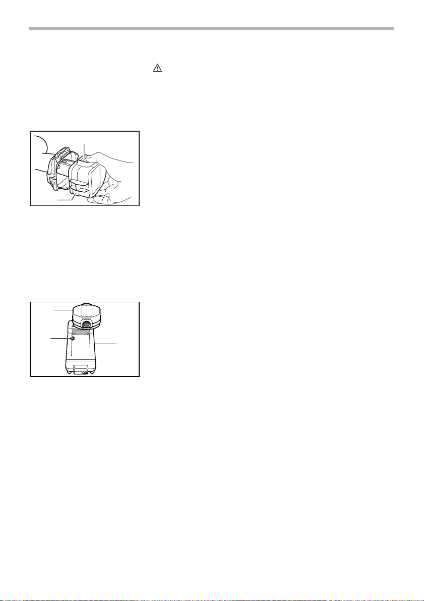
1
2
1. Button
2. Battery cartridge
1
2
1. Battery cartridge
2. Charging light
3. Battery charger
3
CAUTION:
• Always be sure that the tool is switched off and the
battery cartridge is removed before adjusting or
checking function on the tool.
002402
Installing or removing battery cartridge
• Always switch off the tool before insertion or removal of
the battery cartridge.
• To remove the battery cartridge, withdraw it from the tool
while pressing the buttons on both sides of the cartridge.
• To insert the battery cartridge, align the tongue on the
battery cartridge with the groove in the housing and slip
it into place. Always insert it all the way until it locks in
place with a little click. If not, it may accidentally fall out
of the tool, causing injury to you or someone around you.
• Do not use force when inserting the battery cartridge. If
the cartridge does not slide in easily, it is not being
inserted correctly.
004346
Charging
1. Plug the battery charger into the proper AC voltage
source. The charging light will flash in green color.
2. Insert the battery cartridge so that the plus and minus
terminals on the battery cartridge are on the same sides
as their respective markings on the charger. Insert the
cartridge fully into the port so that it rests on the charger
port floor.
3. When the battery cartridge is inserted, the charging light
color will change from green to red and charging will
begin. The charging light will remain lit steadily during
charging.
4. When the charging light color changes from red to
green, the charging cycle is complete.
5. If you leave the battery cartridge in the charger after the
charging cycle is complete, the charger will switch into
its “trickle charge (maintenance charge)” mode.
6. After charging, unplug the charger from the power
source.
8
Page 9

NOTE:
• The battery charger is for charging Makita battery
cartridge. Never use it for other purposes or for other
manufacturer’s batteries.
• When you charge a new battery cartridge or a battery
cartridge which has not been used for a long period of
time, it may not accept a full charge. This is a normal
condition and does not indicate a problem. You can
recharge the battery cartridge fully after discharging it
completely and recharging a couple of times.
• If you charge a battery cartridge from a just operated
tool or a battery cartridge which has been left in a
location exposed to direct sunlight or heat for a long
time, the charging light may flash in red color. If this
occurs, wait for a while. Charging will begin after the
battery cartridge cools. The battery cartridge will cool
faster if you remove the battery cartridge from the
battery charger.
• If the charging light flashes alternately in green and red
color, charging is not possible. The terminals on the
charger or battery cartridge are clogged with dust or the
battery cartridge is worn out or damaged.
Trickle charge (Maintenance charge)
If you leave the battery cartridge in the charger to prevent
spontaneous discharging after full charge, the charger will
switch into its “trickle charge (maintenance charge)” mode
and keep the battery cartridge fresh and fully charged.
Tips for maintaining maximum battery life
1. Charge the battery cartridge before completely discharged.
Always stop tool operation and charge the battery cartridge when you notice less tool power.
2. Never recharge a fully charged battery cartridge.
Overcharging shortens the battery service life.
3. Charge the battery cartridge with room temperature at
10°C - 40°C (50°F - 104°F).
Let a hot battery cartridge cool down before charging it.
4. Charge the Nickel Metal Hydride battery cartridge when
you do not use it for more than six months.
9
Page 10

1
1. Switch trigger
1
A
1. Reversing switch lever
002404
Switch action
CAUTION:
• Before inserting the battery cartridge into the tool,
always check to see that the switch trigger actuates
properly and returns to the “OFF” position when
released.
To start the tool, simply pull the switch trigger. Tool speed is
increased by increasing pressure on the switch trigger.
Release the switch trigger to stop.
Electric brake
This tool is equipped with an electric brake. If the tool consistently fails to quickly stop after switch trigger release, have
tool serviced at a Makita service center.
002409
Reversing switch action
This tool has a reversing switch to change the direction of
rotation. Depress the reversing switch lever from the A side
for clockwise rotation or from the B side for counterclockwise
B
rotation.
When the reversing switch lever is in the neutral position, the
switch trigger cannot be pulled.
CAUTION:
• Always check the direction of rotation before operation.
• Use the reversing switch only after the tool comes to a
complete stop. Changing the direction of rotation before
the tool stops may damage the tool.
• When not operating the tool, always set the reversing
switch lever to the neutral position.
1
1. Speed change lever
10
002414
Speed change
To change the speed, first switch off the tool and then slide
the speed change lever to the “II” side for high speed or “I”
side for low speed. Be sure that the speed change lever is
set to the correct position before operation. Use the right
speed for your job.
Page 11

1. Action mode changing ring
2. Arrow
2
1. Graduations
2. Adjusting ring
3. Arrow
1
2
1
3
CAUTION:
• Always set the speed change lever fully to the correct
position. If you operate the tool with the speed change
lever positioned halfway between the “I” side and “II”
side, the tool may be damaged.
• Do not use the speed change lever while the tool is
running. The tool may be damaged.
002419
Selecting the action mode
This tool employs an action mode changing ring. Select one
of the three modes suitable for your work needs by using this
ring.
For rotation only, turn the ring so that the arrow on the tool
body points toward the mark on the ring.
For rotation with hammering, turn the ring so that the arrow
points toward the mark on the ring.
For rotation with clutch, turn the ring so that the arrow points
toward the mark on the ring.
CAUTION:
• Always set the ring correctly to your desired mode mark.
If you operate the tool with the ring positioned halfway
between the mode marks, the tool may be damaged.
002426
Adjusting the fastening torque
The fastening torque can be adjusted in 16 steps by turning
the adjusting ring so that its graduations are aligned with the
arrow on the tool body. The fastening torque is minimum
when the number 1 is aligned with the arrow, and maximum
when the number 16 is aligned with the arrow.
Before actual operation, drive a trial screw into your material
or a piece of duplicate material to determine which torque
level is required for a particular application.
ASSEMBLY
CAUTION:
• Always be sure that the tool is switched off and the
battery cartridge is removed before carrying out any
work on the tool.
11
Page 12

2
1. Teeth
2. Grip base
3. Side grip
1. Sleeve
002427
Installing side grip (auxiliary handle)
1
Always use the side grip to ensure operating safety. Install
the side grip so that the teeth on the grip fit in between the
3
protrusions on the tool barrel.
Then tighten the grip by turning clockwise at the desired
position. It may be swung 360° so as to be secured at any
position.
002431
Installing or removing driver bit or drill bit
Turn the sleeve counterclockwise to open the chuck jaws.
Place the bit in the chuck as far as it will go. Turn the sleeve
1
clockwise to tighten the chuck.
To remove the bit, turn the sleeve counterclockwise.
002432
When not using the driver bit, keep it in the bit holders. Bits
45 mm (1-3/4”) long can be kept there.
1
1. Bit
2. Bit holder
1. Depth rod
2. Clamp screw
12
2
002437
Adjustable depth rod
1
The adjustable depth rod is used to drill holes of uniform
depth. Loosen the clamp screw, set to desired position, then
tighten the clamp screw.
2
Page 13

OPERATION
Hammer drilling operation
CAUTION:
• There is a tremendous and sudden twisting force
exerted on the tool/bit at the time of hole break-through,
when the hole becomes clogged with chips and
particles, or when striking reinforcing rods embedded in
the concrete. Always use the side grip (auxiliary handle)
and firmly hold the tool by both side grip and switch
handle during operations. Failure to do so may result in
the loss of control of the tool and potentially severe
injury.
First, turn the action mode changing ring so that the arrow on
the tool body points to the marking. The adjusting ring can
be aligned in any torque levels for this operation.
Be sure to use a tungsten-carbide tipped bit.
Position the bit at the desired location for the hole, then pull
the switch trigger. Do not force the tool. Light pressure gives
best results. Keep the tool in position and prevent it from slipping away from the hole.
Do not apply more pressure when the hole becomes clogged
with chips or particles. Instead, run the tool at an idle, then
remove the bit partially from the hole. By repeating this several times, the hole will be cleaned out and normal drilling
may be resumed.
1. Blow-out bulb
1
002449
Blow-out bulb (optional accessory)
After drilling the hole, use the blow-out bulb to clean the dust
out of the hole.
13
Page 14

002450
Screwdriving operation
First, turn the action mode changing ring so that the arrow on
the tool body points to the marking. Adjust the adjusting
ring to the proper torque level for your work. Then proceed as
follows.
Place the point of the driver bit in the screw head and apply
pressure to the tool. Start the tool slowly and then increase
the speed gradually. Release the switch trigger as soon as
the clutch cuts in.
NOTE:
• Make sure that the driver bit is inserted straight in the
screw head, or the screw and/or bit may be damaged.
• When driving wood screws, predrill pilot holes to make
driving easier and to prevent splitting of the workpiece.
See the chart.
Nominal diameter
of wood screw (mm)
3.1 mm (1/8”)
3.5 mm (9/64”)
3.8 mm (5/32”)
4.5 mm (11/64”)
4.8 mm (3/16”)
5.1 mm (13/64”)
5.5 mm (7/32”)
5.8 mm (7/32”)
6.1 mm (15/64”)
Recommended size
of pilot hole (mm)
2.0 - 2.2 mm (5/64” - 3/32”)
2.2 - 2.5 mm (3/32” - 3/32”)
2.5 - 2.8 mm (3/32” - 7/64”)
2.9 - 3.2 mm (7/64” - 1/8”)
3.1 - 3.4 mm (1/8” - 9/64”)
3.3 - 3.6 mm (1/8” - 9/64”)
3.7 - 3.9 mm (9/64” - 5/32”)
4.0 - 4.2 mm (5/32” - 11/64”)
4.2 - 4.4 mm (11/64” - 11/64”)
14
• If the tool is operated continuously until the battery
cartridge has discharged, allow the tool to rest for 15
minutes before proceeding with a fresh battery.
Page 15

Drilling operation
CAUTION:
• Pressing excessively on the tool will not speed up the
drilling. In fact, this excessive pressure will only serve to
damage the tip of your bit, decrease the tool
performance and shorten the service life of the tool.
• There is a tremendous force exerted on the tool/bit at the
time of hole break through. Hold the tool firmly and exert
care when the bit begins to break through the workpiece.
• A stuck bit can be removed simply by setting the
reversing switch to reverse rotation in order to back out.
However, the tool may back out abruptly if you do not
hold it firmly.
• Always secure small workpieces in a vise or similar holddown device.
• If the tool is operated continuously until the battery
cartridge has discharged, allow the tool to rest for 15
minutes before proceeding with a fresh battery.
First, turn the action mode changing ring so that the arrow on
the tool body points to the marking. The adjusting ring can
be aligned in any torque levels for this operation. Then proceed as follows.
Drilling in wood
When drilling in wood, the best results are obtained with
wood drills equipped with a guide screw. The guide screw
makes drilling easier by pulling the bit into the workpiece.
Drilling in metal
To prevent the bit from slipping when starting a hole, make
an indentation with a center-punch and hammer at the point
to be drilled. Place the point of the bit in the indentation and
start drilling.
Use a cutting lubricant when drilling metals. The exceptions
are iron and brass which should be drilled dry.
15
Page 16

MAINTENANCE
1
1. Limit mark
1
2
1. Brush holder cap
2. Screwdriver
CAUTION:
• Always be sure that the tool is switched off and the
battery cartridge is removed before attempting to
perform inspection or maintenance.
001145
Replacing carbon brushes
Remove and check the carbon brushes regularly. Replace
when they wear down to the limit mark. Keep the carbon
brushes clean and free to slip in the holders. Both carbon
brushes should be replaced at the same time. Use only identical carbon brushes.
002453
Use a screwdriver to remove the brush holder caps. Take out
the worn carbon brushes, insert the new ones and secure
the brush holder caps.
After replacing brushes, insert the battery cartridge into the
tool and break in brushes by running tool with no load for
about 1 minute. Then check the tool while running and electric brake operation when releasing the switch trigger. If electric brake is not working well, ask your local Makita service
center for repair.
To maintain product SAFETY and RELIABILITY, repairs, any
other maintenance or adjustment should be performed by
Makita Authorized or Factory Service Centers, always using
Makita replacement parts.
16
Ni-Cd
EN0001-1
Recycling the Battery
The only way to dispose of a Makita battery is to recycle it.
The law prohibits any other method of disposal.
To recycle the battery:
1. Remove the battery from the tool.
2. a) Take the battery to your nearest Makita Factory Service Center
or
b) Take the battery to your nearest Makita Authorized
Service Center or Distributor that has been designated as a Makita battery recycling location.
Page 17

Call your nearest Makita Service Center or Distributor to
determine the location that provides Makita battery recycling.
See your local Yellow Pages under “Tools-Electric”.
ACCESSORIES
CAUTION:
• These accessories or attachments are recommended for
use with your Makita tool specified in this manual. The
use of any other accessories or attachments might
present a risk of injury to persons. Only use accessory
or attachment for its stated purpose.
If you need any assistance for more details regarding these
accessories, ask your local Makita service center.
• Drill bits
• Hammer drill bits
• Screw bits
• Blow-out bulb
• Safety goggles
• Various type of Makita genuine batteries and chargers
• Grip assembly
• Depth rod
• Rubber pad assembly
• Wool bonnet
• Foam polishing pad
• Plastic carrying case
17
Page 18

Memo
18
Page 19

Memo
19
Page 20

Memo
20
Page 21

Cut
Makita U.S.A., Inc.
14930 Northam Street
La Mirada, CA 90638-5753
Fold
First-Class
Postage
Required
Post Office will
not deliver
without proper
postage.
21
Page 22

MAIL THIS PORTION
Your answers to the following questions are appreciated.
1. This product was purchased from:
Home Center
Hardware/Lumber Store
Tool Distributor
Industrial Supply
Construction Supply
2. Use of the product is intended for:
Construction Trade
Industrial Maintenance
Home Maintenance
Hobby
Other ( )
5. Any comments:
DATE PURCHASED MODEL NO.
MONTH DAY YEAR
INTL. LAST NAME / COMPANY NAME
Other ( )
3. How did you learn about this product:
4. Most favored points are:
SERIAL NO.
Magazine
From Dealer
Newspaper
Store Display
Catalog
Design
Features
Size
Price
Makita Brand
Radio
Exhibition
From Friend
Previous Usage
Other ( )
Repair Service
Durability
Powe r
Other ( )
STATUS
Married
Single
SEX
MF
STREET ADRESS
CITY
AREA
S TATE
AGE:
BE SURE TO COMPLETE THE CUSTOMER’S PORTION OF THIS FORM AND RETAIN FOR YOUR RECORDS.
Paste Paste Paste Paste Paste Paste
22
Please return this portion by facsimile or mail.
Facsimile No: (714) 522-8133
ZIP CODE PHONE
Under 19 20-29 30-39 40-49 50-60 Over 60
CODE
Paste Paste Paste Paste Paste Paste Paste Paste
Paste Paste Paste Paste Paste Paste
Page 23

FACTORY SERVICE CENTERS
1-800-4-MAKITA
RETAIN THIS PORTION FOR YOUR RECORDS
ARIZONA
3707 E. Broadway Rd., Ste. 6
Phoenix, AZ 85040
(602) 437-2850
CALIFORNIA
41850 Christy St.
Fremont, CA 94538-5107
(510) 657-9881
14930 Northam St.
La Mirada, CA 90638-5753
(714) 522-8088
1970 Fulton Avenue
Sacramento, CA 95825
(916) 482-5197
7674 Clairemont Mesa Blvd.
San Diego, CA 92111
(858) 278-4471
16735 Saticoy St., Ste. 105
Van Nuys, CA 91406
(818) 782-2440
COLORADO
11839 E. 51st Ave.
Denver, CO 80239-2709
(303) 371-2850
FLORIDA
750 East Sample Road
Pompano Beach, FL 33064
(954) 781-6333
GEORGIA
4680 River Green Parkway NW
Duluth, GA 30096
(770) 476-8911
ILLINOIS
1450 Feehanville Dr.
Mt. Prospect, IL 60056-6011
(847) 297-3100
MARYLAND
7397 Washington Boulevard,
Suite 104 Elkridge, MD 21075
(410) 796-4401
MASSACHUSETTS
232 Providence Hwy.
Westwood, MA 02090
(781) 461-9754
MINNESOTA
6427 Penn Ave. South
Richfield, MN 55423
(612) 869-5199
MISSOURI
9876 Watson Road
St. Louis, MO 63126-2221
(314) 909-9889
NEBRASKA
4129 S. 84th St.
Omaha, NE 68127
(402) 597-2925
NEVADA
3375 S. Decatur Blvd.
Suites. 22 - 24
Las Vegas, NV 89102
(702) 368-4277
NEW JERSEY
251 Herrod Blvd.
Dayton, NJ 08810-1539
(609) 655-1212
NEW YORK
4917 Genessee Street
Cheektowaga, NY 14225
(716) 685-9503
OREGON
828 19th Avenue, N.W.
Portland, OR 97209
(503) 222-1823
PENNSYLVANIA
1704 Babcock Blvd.
Pittsburgh, PA 15209
(412) 822-7370
PUERTO RICO
200 Guayama St.
Hato Rey, PR 00917
(787) 250-8776
TENNESSEE
1120 Elm Hill P.
Suile 170 Nashville, TN 372
(615) 248-3321
TEXAS
12801 Stemmons Fwy Ste. 809
Farmers Branch, TX 75234
(972) 243-1150
12701 Directors Dr.
Stafford, TX 77477-3701
(281) 565-8665
3453 IH-35 North, Ste. 101
San Antonio, TX 78219
(210) 228-0676
WISCONSIN
Lincoln Plaza Shopping Ctr.
2245 S. 108th St. West Allis, WI
53227
(414) 541-4776
CUSTOMER’S RECORD
When you need service: Send
complete tool (prepaid) to one
of the Makita Factory Service
Centers listed, or to an Authorized
Makita Service Center. Be sure
to attach a letter to the outside of
the carton detailing the problem
with your tool.
Date Purchased
Dealer’s Name & Address
Model No.
Serial No.
23
Page 24

WARNING
Some dust created by power sanding, sawing, grinding, drilling, and other
construction activities contains chemicals known to the State of California
to cause cancer, birth defects or other reproductive harm. Some examples
of these chemicals are:
• lead from lead-based paints,
• crystalline silica from bricks and cement and other masonry products, and
• arsenic and chromium from chemically-treated lumber.
Your risk from these exposures varies, depending on how often you do this
type of work. To reduce your exposure to these chemicals: work in a well
ventilated area, and work with approved safety equipment, such as those
dust masks that are specially designed to filter out microscopic particles.
MAKITA LIMITED ONE YEAR WARRANTY
Warranty Policy
Every Makita tool is thoroughly inspected and tested before leaving the factory. It is warranted to be free of
defects from workmanship and materials for the period of ONE YEAR from the date of original purchase.
Should any trouble develop during this one year period, return the COMPLETE tool, freight prepaid, to one of
Makita’s Factory or Authorized Service Centers. If inspection shows the trouble is caused by defective
workmanship or material, Makita will repair (or at our option, replace) without charge.
This Warranty does not apply where:
• repairs have been made or attempted by others:
• repairs are required because of normal wear and tear:
• the tool has been abused, misused or improperly maintained:
• alterations have been made to the tool.
IN NO EVENT SHALL MAKITA BE LIABLE FOR ANY INDIRECT, INCIDENTAL OR CONSEQUENTIAL
DAMAGES FROM THE SALE OR USE OF THE PRODUCT. THIS DISCLAIMER APPLIES BOTH DURING
AND AFTER THE TERM OF THIS WARRANTY.
MAKITA DISCLAIMS LIABILITY FOR ANY IMPLIED WARRANTIES, INCLUDING IMPLIED WARRANTIES OF
“MERCHANTABILITY” AND “FITNESS FOR A SPECIFIC PURPOSE,” AFTER THE ONE YEAR TERM OF THIS
WARRANTY.
This Warranty gives you specific legal rights, and you may also have other rights which vary from state to state.
Some states do not allow the exclusion or limitation of incidental or consequential damages, so the above
limitation or exclusion may not apply to you. Some states do not allow limitation on how long an implied
warranty lasts, so the above limitation may not apply to you.
884288D983
Makita Corporation of America
2650 Buford Hwy., Buford, GA 30518
 Loading...