

Page 1
2-Speed Hammer Drill
8419B-2
DOUBLE
INSULATION
Page 2
SPECIFICATIONS
Model 8419B-2
Capacities
Wood................................................................................................................................... High: 18 mm (3/4”)
Low: 30 mm (1-1/8”)
Steel ................................................................................................................................... High: 6.5 mm (1/4”)
Low: 13 mm (1/2”)
Concrete............................................................................................................................ High: 14 mm (9/16”)
Low: 19 mm (3/4”)
No load speed (RPM) ....................................................................................................................... High: 2,300
Low: 900
Blows per minute ............................................................................................................................. High: 46,000
Low: 18,000
Overall length ...........................................................................................................................350 mm (13-3/4”)
Net weight .......................................................................................................................................3 kg (6,6 lbs)
• Due to our continuing programme of research and development, the specifications herein are subject to change with-
out notice.
• Note: Specifications may differ from countr y to country.
Power s up ply
The tool should be connected only to a power supply of the same voltage as indicated on the nameplate, and can only
be operated on single-phase AC supply. They are double-insulated in accordance with European Standard and can,
therefore, also be used from sockets without earth wire.
For European countries only
Noise and Vibration
The typical A-weighted noise levels are
The typical weighted root mean square acceleration
value is 8 m/s
The undersigned, Yasuhiko Kanzaki, authorized by
Makita Corporation, 3-11-8 Sumiyoshi-Cho, Anjo, Aichi,
446 Japan declares that this product
manufactured by Makita Corporation in Japan is in compliance with the following standards or standardized documents,
in accordance with Council Directives, 73/23/EEC,
89/336/EEC and 98/37/EC.
sound pressure level: 99 dB (A)
sound power level: 112 dB (A)
– Wear ear protection. –
2
.
EC-DECLARATION OF CONFORMITY
(Serial No. : series production)
HD400, EN50144, EN55014, EN61000*
*from 1st Jan. 2001
Yasuhiko Kanzaki
CE 94
Symbols
The followings show the symbols used for the tool. Be
sure that you understand their meaning before use.
❏ Read instruction manual.
❏ Wear safety glasses.
❏ Only for EU countries
Do not dispose of electric equipment
together with household waste material!
In observance of European Directive 2002/
96/EC on waste electrical and electronic
equipment and its implementation in accordance with national law, electric equipment
that have reached the end of their life must
be collected separately and returned to an
environmentally compatible recycling facility.
Director
MAKITA INTERNATIONAL EUROPE LTD.
Michigan Drive, Tongwell, Milton Keynes,
Bucks MK15 8JD, ENGLAND
2
Page 3
12
34
56
78
3
Page 4

ENGLISH
1 Change ring
2 Chuck key
3 Tighten
Explanation of general view
4 Depth gauge
5 Change lever
6 Trigger switch
7 Lock button
SAFETY INSTRUCTIONS
Warning! When using electric tools, basic safety precautions should always be followed to reduce the
risk of fire, electric shock and personal injury, including the following. Read all these instructions before
attempting to operate this product and save these
instructions.
For safe operation:
1. Keep work area clean
Cluttered areas and benches invite injuries.
2. Consider work area environment
Don’t expose power tools to rain. Don’t use power
tools in damp or wet locations. Keep work area well
lit. Don’t use power tools in presence of flammable
liquids or gases.
3. Guard against electric shock
Prevent body contact with grounded surfaces
(e.g. pipes, radiators, ranges, refrigerators).
4. Keep children away
Do not let visitors contact tool or extension cord.
All visitors should be kept away from work area.
5. Store idle tools
When not in use, tools should be stored in dry, high,
or locked-up place, out of the reach of children.
6. Don’t force tool
It will do the job better and safer at the rate for which
it was intended.
7. Use right tool
Don’t force small tools or attachments to do the job
of a heavy duty tool. Don’t use tools for purposes not
intended; for example, don’t use circular saw for cutting tree limbs or logs.
8. Dress properly
Do not wear loose clothing or jeweller y. They can be
caught in moving parts. Rubber gloves and non-skid
footwear are recommended when working outdoors.
Wear protective hair covering to contain long hair.
9. Use safety glasses and hearing protection
Also use face or dust mask if cutting operation is
dusty.
10. Connect dust extraction equipment
If devices are provided for the connection of dust
extraction and collection facilities, ensure these are
connected and proper ly used.
11. Don’t abuse cord
Never carry tool by cord or yank it to disconnect it
from receptacle. Keep cord from heat, oil and sharp
edges.
12. Secure work
Use clamps or a vice to hold work. It’s safer than
using your hand and it frees both hands to operate
tool.
13. Don’t overreach
Keep proper footing and balance at all times.
14. Maintain tools with care
Keep tools sharp and clean for better and safer performance. Follow instructions for lubricating and
changing accessories. Inspect tool cords periodically and, if damaged, have repaired by authorised
service facility. Inspect extension cords periodically
and replace if damaged. Keep handles dry, clean
and free from oil and grease.
15. Disconnect tools
When not in use, before servicing, and when changing accessories such as blades, bits and cutters.
16. Remove adjusting keys and wrenches
Form the habit of checking to see that keys and
adjusting wrenches are removed from tool before
turning it on.
17. Avoid unintentional starting
Don’t carry plugged-in tool with finger on switch.
Be sure switch is off when plugging in.
18. Outdoor use extension cords
When tool is used outdoors, use only extension
cords intended for use outdoors and so marked.
19. Stay alert
Watch what you are doing. Use common sense.
Do not operate tool when you are tired.
20. Check damaged parts
Before further use of the tool, a guard or other part
that is damaged should be carefully checked to
determine that it will operate properly and perform
its intended function. Check for alignment of moving
parts, binding of moving parts, breakage of par ts,
mounting, and any other conditions that may affect
its operation. A guard or other par t that is damaged
should be properly repaired or replaced by an
authorised service centre unless otherwise indicated
elsewhere in this instruction manual. Have defective
switches replaced by and author ised service centre.
Do not use tool if switch does not turn it on and off.
21. Warning
The use of any other accessory or attachment other
than recommended in this operating instruction or
the catalogue may present a risk of personal injury.
22. Have your tool repaired by an expert
This electric appliance is in accordance with the relevant safety rules. Repairing of electric appliances
may be carried out only by experts otherwise it may
cause considerable danger for the user.
ADDITIONAL SAFETY RULES
1. Wear a hard hat (safety helmet), safety glasses
and/or face shield. It is also highly recommended that you wear a dust mask, ear protectors and thickly padded gloves.
2. Under normal operation, the tool is designed to
produce vibration. The screws can come loose
easily, causing a breakdown or accident. Check
tightness of screws carefully before operation.
3. Always be sure you have a firm footing. Be sure
no one is below when using the tool in high locations.
4
Page 5

4. Hold the tool firmly with both hands. Always use
the side grip.
5. Keep hands away from rotating parts.
6. Do not leave the tool running. Operate the tool
only when hand-held.
7. When drilling into walls, floors or wherever
‘‘live’’ electrical wires may be encountered, DO
NOT TOUCH ANY METAL PARTS OF THE TOOL!
Hold the tool by the insulated grasping surfaces
to prevent electric shock if you drill into a ‘‘live’’
wire.
8. Do not touch the bit or the workpiece immediately after operation; they may be extremely hot
and could burn your skin.
SAVE THESE INSTRUCTIONS.
OPERATING INSTRUCTIONS
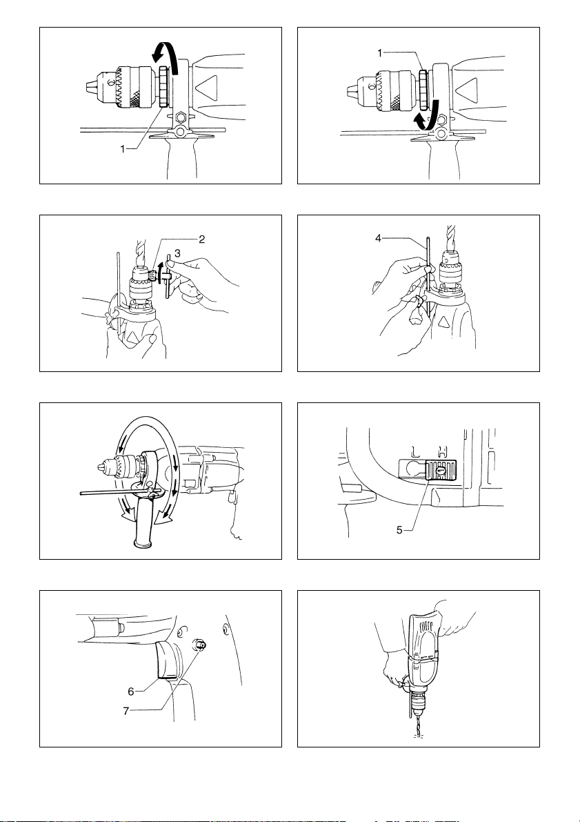
Selecting action mode
Rotation with hammering (Fig. 1)
For drilling in concrete, granite, tile, etc., turn the change
ring in the direction of
concrete and masonry drilling bit.
Rotation only (Fig. 2)
For drilling in wood, metal or plastic materials, turn the
change ring in the direction of
conventional bit for drilling in wood or metal.
marking. Be sure to use a
W
V
marking. Use a
Installing or removing drill bit (Fig. 3)
CAUTION:
Always be sure that the tool is switched off and
unplugged before installing or removing the bit.
To install the bit, place it in the chuck as far as it will go.
Tighten the chuck by hand. Place the chuck key in each
of the three holes and tighten clockwise. Be sure to
tighten all three chuck holes evenly.
To remove the bit, turn the chuck key counterclockwise in
just one hole, then loosen the chuck by hand. After using
the chuck key, be sure to retur n it to the original position.
Adjusting depth of drilling (Fig. 4)
Loosen the wing bolt and adjust the depth gauge to the
desired depth. After adjusting, tighten the wing bolt.
Side grip (auxiliary handle) (Fig. 5)
The side grip swings around to either side, allowing easy
handling of the tool in any position. Loosen the wing nut,
swing the side grip to the desired position and then
tighten the wing nut.
Speed change (Fig. 6)
To change the tool speed, press the change lever and
slide it to the ‘‘L’’ position for low speed or the ‘‘H’’ position
for high speed. If the change lever does not slide easily,
turn the chuck slightly in either direction while sliding the
change lever.
Switch action (Fig. 7)
To start the tool, simply pull the trigger. Release the trigger to stop. For continuous operation, pull the trigger and
then push in the lock button. To stop the tool from the
locked position, pull the trigger fully, then release it.
CAUTION:
Before plugging in the tool, always check to see that the
trigger switch actuates properly and returns to the ‘‘OFF’’
position when released.
Hammer drilling operation (Fig. 8)
Position the bit at the location for the hole, then pull the
trigger. Do not force the tool. Light pressure gives best
results. Keep the tool in position and prevent it from slipping away from the hole.
Do not apply more pressure when the hole becomes
clogged with chips or particles. Instead, run the tool at an
idle, then remove from the hole. By repeating this several
times, the hole will be cleaned out.
Drillng operation
• Drilling in wood
When drilling in wood, best results are obtained with
wood drills equipped with a guide screw. The guide
screw makes drilling easier by pulling the bit into the
workpiece.
• Drilling in metal
To prevent the bit from slipping when starting a hole,
make an indentation with a centerpunch and hammer
at the point to be drilled. Place the point of the bit in the
indentation and start drilling.
Use a cutting lubricant when drilling metals. The exceptions are iron and brass which should be drilled dry.
CAUTION:
• Pressing excessively on the tool will not speed up the
drilling. In fact, this excessive pressure will only serve
to damage the tip of your bit, decrease the tool performance and shorten the service life of the tool.
• There is a tremendous force exerted on the tool/bit at
the time of hole breakthrough. Hold the tool firmly and
exert care when the bit begins to break through the
workpiece.
• Always secure small workpieces in a vise or similar
hold-down device.
MAINTENANCE
CAUTION:
Always be sure that the tool is switched off and
unplugged before attempting to perform inspection or
maintenance.
To maintain product SAFETY and RELIABILITY, repairs,
carbon brush inspection and replacement, any other
maintenance or adjustment should be performed by Makita Authorized or Factory Service Centers, always using
Makita replacement parts.
5
Page 6

ACCESSORIES
CAUTION:
These accessories or attachments are recommended for use with your Makita tool specified in this manual. The use of
any other accessories or attachments might present a risk of injury to persons. The accessories or attachments should
be used only in the proper and intended manner.
• Tungsten-carbide tipped bit
L
D
M
* ‘‘M’’ stands for max. drilling depth.
D (mm) 5 6.5 7.5 8 8.5 9.5 10.5 11 12.5 14 16 19
L (mm) 70 80 90 120 100 180 120 150 180 300 220
M (mm) 40 50 60 95 75 155 95 125 155 275 160
6
Page 7

7
Page 8

Makita Corporation
Anjo, Aichi, Japan
883097A228
 Loading...