

Makita 8280D, 8280DWAE, 8280DZ, 8280DWALE, 8280DWE Technical Information
...
T
ECHNICAL INFORMATION
Models No.
8280D
PRODUCT
P 1 / 5
Description
Cordless Percussion Driver Drill
CONCEPT AND MAIN APPLICATIONS
Models 8280D has been developed by adding percussion mechanism to
Model 6280D for a compact, yet powerful and durable 14.4V cordless percussion
driver drill. Its brief advantages are;
*Compact design with an overall length of only 214mm (8-3/8")
*Very versatile with 3 work modes; Percussion drill, Drill, Screwdriver
*All metal gear construction for extra-high transmission durability
This new product is available in the variations listed below.
Model No.
8280DZ without without
8280DWAE
8280DWALE
8280DWE
8280DWLE
8280DWPE
8280DWPLE Ni-Cd Battery PA14 (1.3Ah)
8280DWPE3
Ni-Cd Battery 1422 (2.0Ah)
Ni-Cd Battery 1420 (1.3Ah)
Battery
Type Q'ty
2
2
2
2 ML140
2
2
3
Charger
DC1414
Rechargeable
flashlight
without
without
ML140
without
without
ML140
without
L
H
Dimensions: mm (")
Length (L) 214 (8-3/8)
Width (W)
Height (H)
94 (3-11/16)
243 (9-9/16)
W
Specification
Voltage: (V)
Battery
No load speed:
min-1=rpm
Impact per minute:
min-1=bpm
Chuck capacity: mm ( " )
Capacities
Max. fastening
torque: N.m
Torque adjustment
Net weight: kg (lbs) [includes battery]
Cell
Capacity: (Ah)
High speed
Low speed
High speed
Low speed
Steel: mm ( " )
Wood: mm ( " )
Masonry: mm ( " )
1.3 Ah (Battery 1420, PA14) 2.0 Ah (Battery 1422)
0.8 - 10 (1/32 - 3/8)
Hard joint
Soft joint
16 stages plus drill mode
Standard equipment
Model No.
(+) (-) Bit 2-65
Battery cover
Plastic carrying case
Note: The standard equipment listed above may differ from country to country.
8280DZ
1
No
No
8280DWAE, 8280DWALE, 8280DWE,
8280DWLE, 8280DWPE, 8280DWPLE
1
2
Yes
14.4
Ni-Cd
0 - 1,200
0 - 350
0 - 18,000
0 - 5,250
10 (3/8)
25 (1)
10 (3/8)
36
20
1.7 (3.7)
8280DWPE3
1
3
Yes
Optional accessories
Battery 1420
Battery PA14
Battery 1422
Battery 1434
Battery 1435
Battery 1435F
Charger DC1414
Charger DC1804
Charger DC1439
Automotive charger DC1422
Automotive charger DC1822
Assorted drill bits for wood
Assorted drill bits for steel
Assorted driver bits
Assorted TCT drill bits
P 2 / 5
Repair
[1] Removal/Installation of Drill Chuck
When replacing Gear assembly, remove drill chuck beforehand as described below.
(It is not necessary to remove Drill chuck when disassembling Housing only.)
REMOVAL
1) After fully opening Chuck jaws, remove the chuck screw (M6x22 (-) Flat head screw) by turning it clockwise.
If it is difficult to remove, use a Makita Impact wrench.
2) Slide Speed change lever to the position of "Low", and turn Change ring to "Drill mode".
And then secure one end of a hex wrench with Chuck jaws. Hold the machine firmly, and then remove Drill chuck
by hitting the other end of the hex wrench using plastic hammer to turn Drill chuck counterclockwise. (Fig. 1)
INSTALLATION
1) Secure one end of a hex wrench with Chuck jaws, and the other with vise.
Shift Speed change lever to "Low", and set the machine in the mode of drilling in forward rotation. Hold the grip
of the machine firmly so that your hand cannot be pulled away by reaction torque. And then fasten Spindle to Drill
chuck by pulling the trigger of Switch until Spindle is locked. (Fig. 2)
Note: Release the trigger of Switch just after Spindle is locked. Do not keep on pulling the trigger for longer than
one second.
2) Fasten Drill chuck to Spindle with the chuck screw (M6x22 (-) Flat head screw) by turning it counterclockwise.
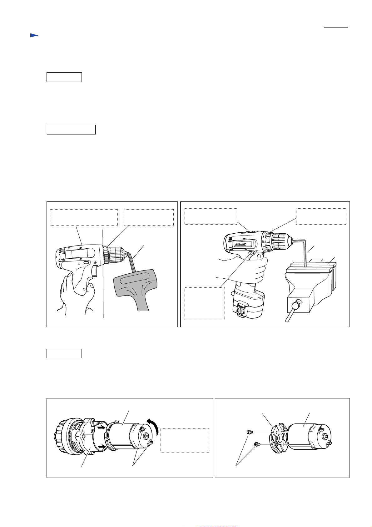
Fig. 1
Slide Speed change lever
to the position of "Low".
Turn Change ring
to "Drill mode".
2
4
6
8
Hex wrench
Fig. 2
Shift Speed change
lever to "Low".
Turn Change ring
to "Drill mode".
Hex wrench
Push in R/F
change lever
for forward
rotation mode.
[2] Removal/Installation of Motor from/on Gear Assembly
REMOVAL
1) Pull Motor out of Gear assembly while turning it in the counterclockwise direction when viewed from the terminal
end of Motor. (Fig. 3)
2) Remove Motor bracket from Motor by removing two Pan head screws. Now Motor can be replaced (Fig. 4)
Vise
Fig. 3 Fig. 4
Motor
Pull Motor
while turning
counterclockwise.
TerminalsGear assembly Pan head screw
Motor bracket
Motor
 Loading...