

Page 1

T
Subject
For Models
ECHNICAL INFORMATION
Change of Light Circuit
BDF430F, BTD123F
73027
April, 2005
(page 1 of 3)
Country
Description
End bell complete
Connector
All countries
Light circuit has been changed for addition of afterglow function.
See illustration below.
Current New
Color index of lead wires' sheath
Switch
Black
Red
Orange
LED circuit
Connector
End bell complete
Switch
Color index of lead wires' sheath
Black
Red
Orange
LED circuit
Part for
Terminal
afterglow
function
Terminal
Interchangeability(I/C)
Current part New part NoteQ'tyItem No.
039 No
007
Light Circuit
631579-6
Light Circuit
631537-2
I/CQ'ty
1
1
Light Circuit
631624-7
Light Circuit
No
631630-2
For BTD123F
1
For BDF430F
1
Implementation
BDF430F: From serial No. 6435E (April, 2005)
BTD123F: From serial No. 2823E (April, 2005)
Assembling way of light circuit
1. Disconnect connector A, and then remove LED circuit B. (Refer to Fig. 1 and 2 in page 2.)
2. Separate insulated terminal C from switch. (Refer to Fig. 2 in page 2.)
3. Detach orange colored lead wire from the root of the insulated terminal C (Refer to Fig. 2 in page 2.)
4. Strip the orange colored lead wire D in 7mm or 8mm. (Refer to Fig. 2 in page 2.)
5. After clamping a stripped end of orange colored lead wire E of new type light circuit and the stripped lead wire D with
insulated terminal RBV1.25-3.5T (Part No. 654037-5), reassemble it to switch terminal. (Refer to Fig. 3 and 4 in page 3.)
6. Connect the connector Fa of the new type light circuit with the connector Fb of lead wire from switch as Fig 4 in page 3.
7. Set LED circuit G of the new type light circuit in place as Fig. 3 in page 3.
8. Install a part for afterglow function H into motor housing as Fig. 4 in page 3. And then fix housing R with housing L.
Operation check of a light with afterglow function
1. Check that the light turns on when pulling a trigger of switch.
2. Check that the light continues to illuminate for about 10 seconds after releasing the trigger.
Page 2
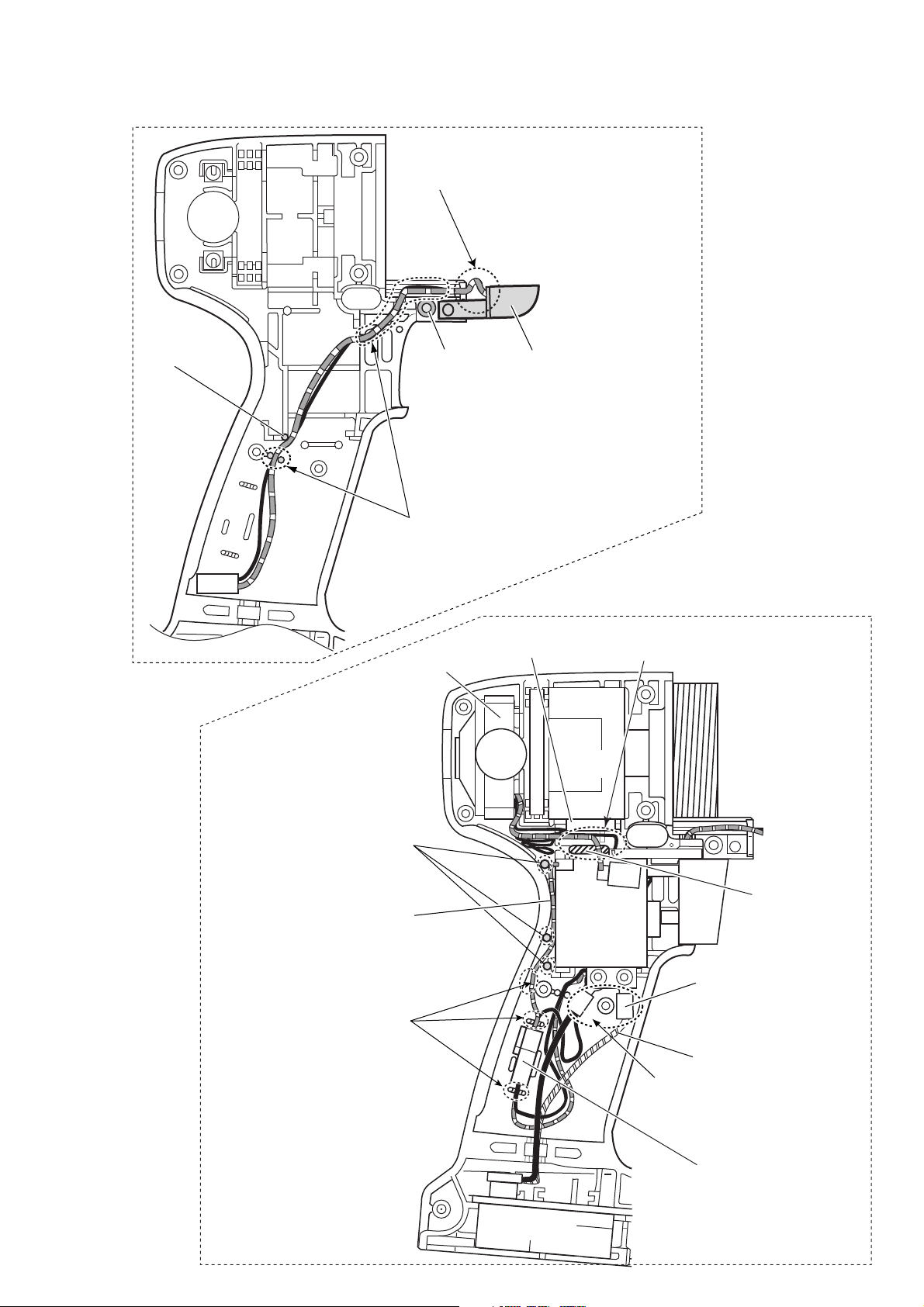
Fig. 1
73027
(page 2 of 3)
The current type cordless tool
Red colored lead wire must be slack in this point.
Pin
Boss
Insert two lead wires for LED circuit
into the bottom of lead wire holders.
Endbell complete
LED circuit B
FET
Route a block colored lead wire (between
Endbell complete and switch) to outside of the rib.
DC
Motor
Fig. 2
Pin
Lead wire (red)
from Switch
Hold the lead wires from Switch
and LED circuit securely with
these lead wire holders.
Rib
Switch
Insulated terminal C
Lead wire D
Insulated terminals should not
touch the boss.
Connector A
Terminal
Page 3
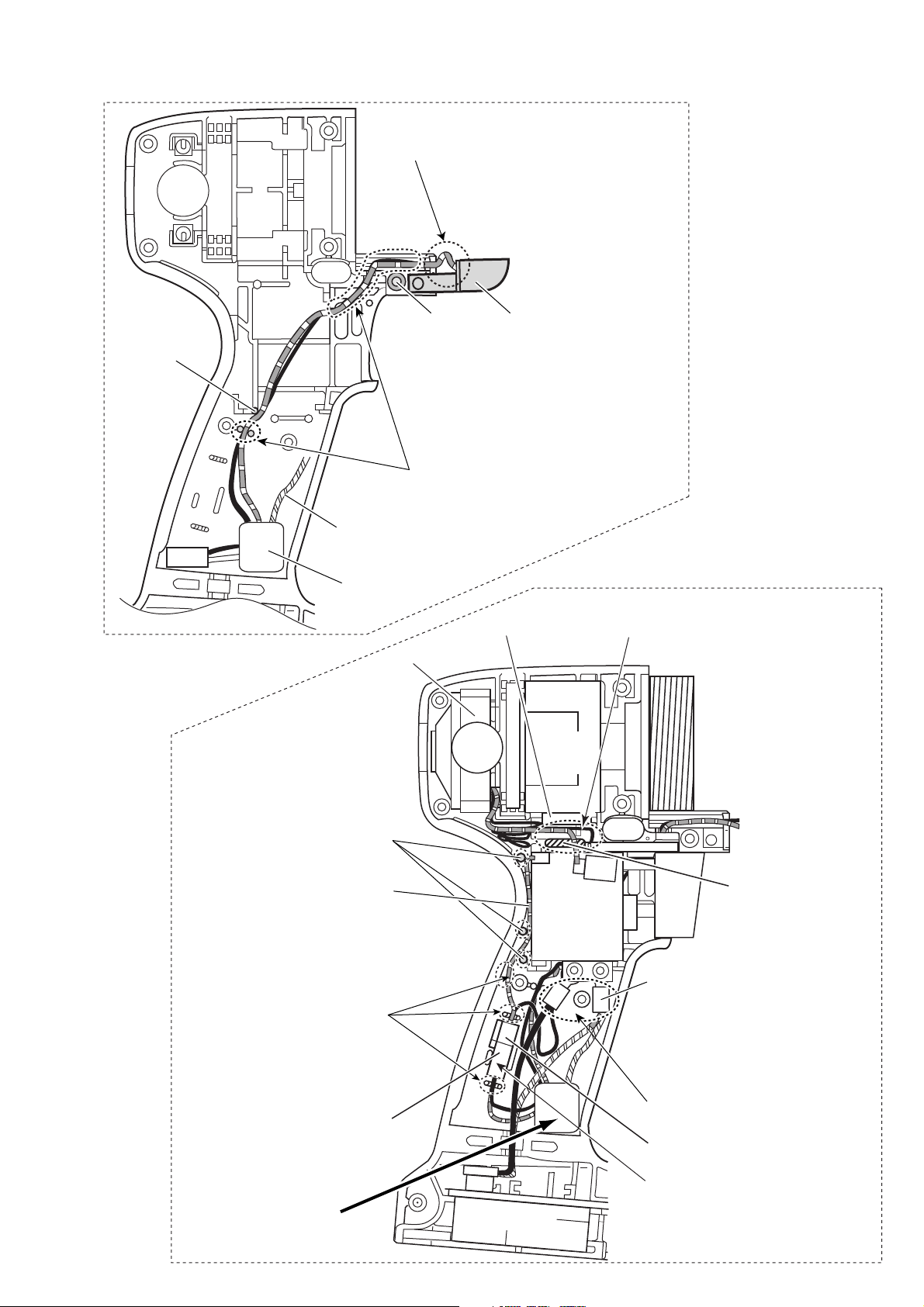
Fig. 3
The new type cordless tool
Red colored lead wire must be slack in this point.
73027
(page 3 of 3)
Pin
Boss
Insert two lead wires for LED circuit
into the bottom of lead wire holders.
Lead wire E
Part for afterglow
function
Endbell complete
LED circuit G
Fig. 4
Route a block colored lead wire (between
FET
Endbell complete and switch) to outside of the rib.
DC
Motor
Pin
Lead wire (red)
from Switch
Hold the lead wires from Switch
and LED circuit securely with
these lead wire holders.
Connector Fa
Part for afterglow
function H
Terminal
Rib
Switch
After clamping a stripped end of
orange colored lead wire E (Re:
Fig. 3) and the stripped lead wire D
(Re: Fig. 2) with insulated terminal
RBV1.25-3.5T (Part No.654037-5),
reassemble it to switch.
Insulated terminals should not
touch the boss.
Connector Fb
Lead wires should not touch
connector Fa and Fb to avoid
being pinched and damaged.
 Loading...