

Page 1
T
Subject
For Models
ECHNICAL INFORMATION
Modification of Housing Set and Guide Plate,
Addition of Stopper Plate, Sub Plate, Torsion Spring 9 and M4x8 Pan Head Screw
BHR200
71250
( Page 1 of 2 )
Country
Description
All countries
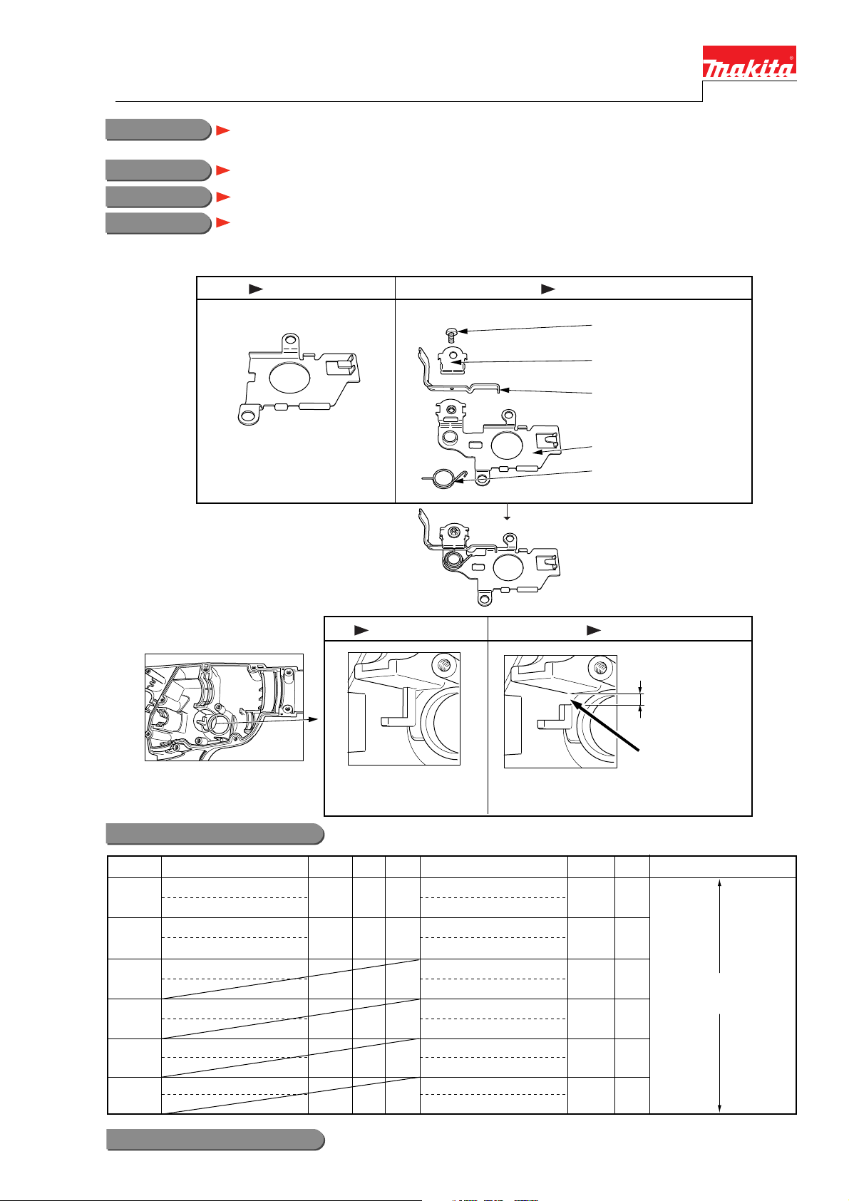
Housing set and Guide plate have been modified.
Stopper plate, Sub plate, Torsion spring 9 and M4x8 pan head screw have been added.
See illustration below for the detail.
Current New
Pan head screw M4x8
(911110-7)
Sub plate
(345456-3)
Stopper plate
(345458-9)
Guide plate
(344900-7)
Guide plate
(345457-1)
Torsion spring 9
(231678-0)
The new parts are assembled
as the left.
Current New
(Housing (L) complete)
Interchangeability(I/C)
Current part
050, 088 11
Housing Set
183393-1
Guide Plate
075
344900-7
092 1
093 1
094 1
095 1
Left side of Housing set
(152864-9)
Housing Set
No
183891-5
Guide Plate
No 11
345457-1
Stopper Plate
345458-9
Sub Plate
345456-3
Torsion Spring 9
231678-0
Pan Head Screw M4x8
911110-7
Left side of Housing set
(154525-7)
New part Note
3mm up to 4mm
Deleted
Q'tyItem No. I/CQ'ty
Interchangeable
as a set
Implementation
From serial No. 90836E (August, 2004)
Page 2
71250
( Page 2 of 2 )
Steps to replace the relevant parts
Remove Guide plate, Change plate and Compression spring 4 from machine in advance.
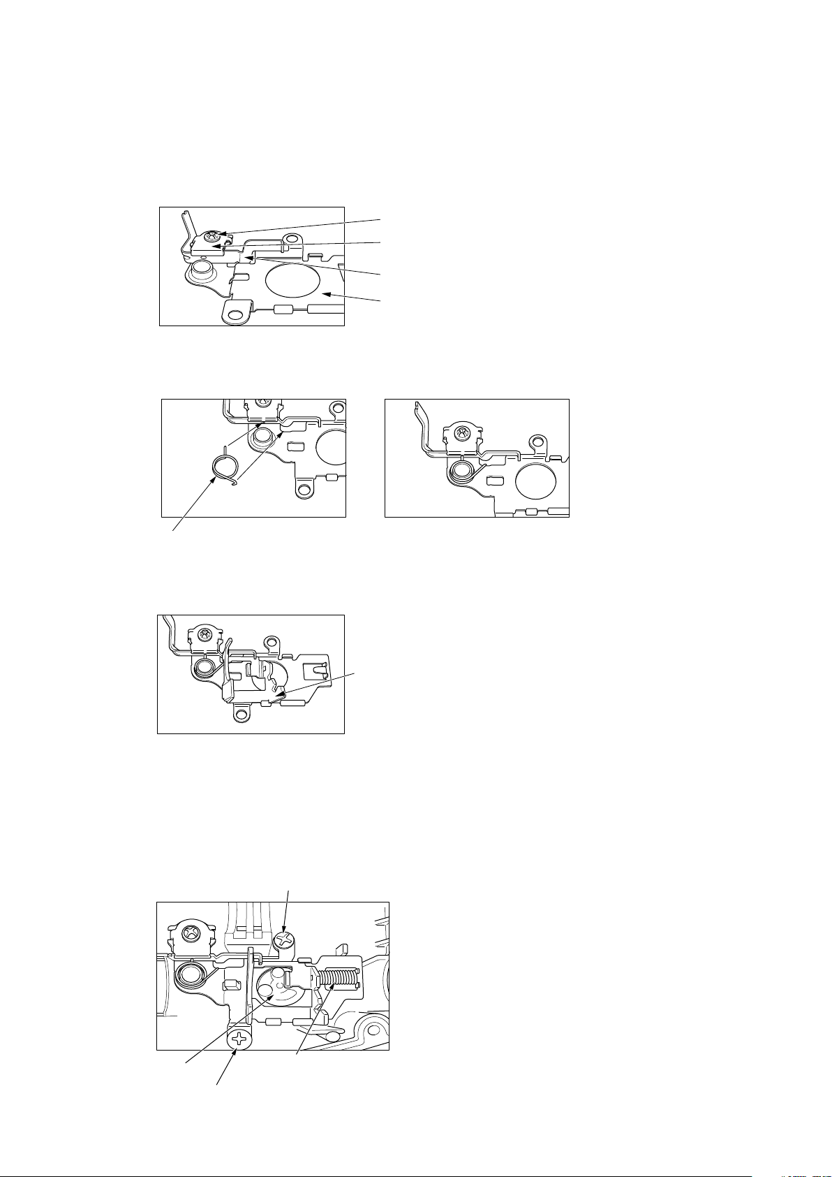
1) After putting Stopper plate on the new Guide plate, hold them with Sub plate by screwing M4x8 Pan head screw
as Fig. 1.
Fig. 1
Pan head screw M4x8 (911110-7)
Sub plate (345456-3)
Stopper plate (345458-9)
Guide plate (345457-1)
2) Insert Torsion spring 9 into the hole of stopper plate as Fig. 2, and then hook it on Guide plate as Fig. 3.
Fig. 2 Fig. 3
Torsion spring 9
(231678-0)
3) Put Change plate between Stopper plate and Guide plate.
(Change plate)
4) See Fig. 4.
Pre-set Change lever to "Hammer mode", and then secure
them with two 4x12 Tapping screws.
Hook compression spring 4 on Guide plate and Change plate.
Shift Change lever to "Hammer drill mode" so that Change plate does not come out of place.
(Tapping screw 4x12)
(Change lever)
(Compression spring 4)
(Tapping screw 4x12)
 Loading...