

Page 1
T
ECHNICAL INFORMATION
Models No.
Description
6993D
Cordless impact
driver 9.6V
6994D
Cordless impact
wrench 9.6V
CONCEPTION AND MAIN APPLICATIONS
The above models are the improved version
of the following existing models.
* 6993D : push button version
of the existing model 6903VD
* 6994D : push button version
of the existing model 6907D
The variations of these models are listed below.
Battery
Model No.
6993D
6993DW
6993DWE
6994DW
6994DWE
Specification
No.
9120
9120
9120
9120
9120
Type
Ni-Cd
Ni-Cd
Ah
1.3
1.3
1.3
1.3
1.3
Q'ty
1 pc.
1 pc.
2 pcs.
1 pc.
2 pcs.
Charger
Without
DC 9710
DC 9710
DC 9710
DC 9710
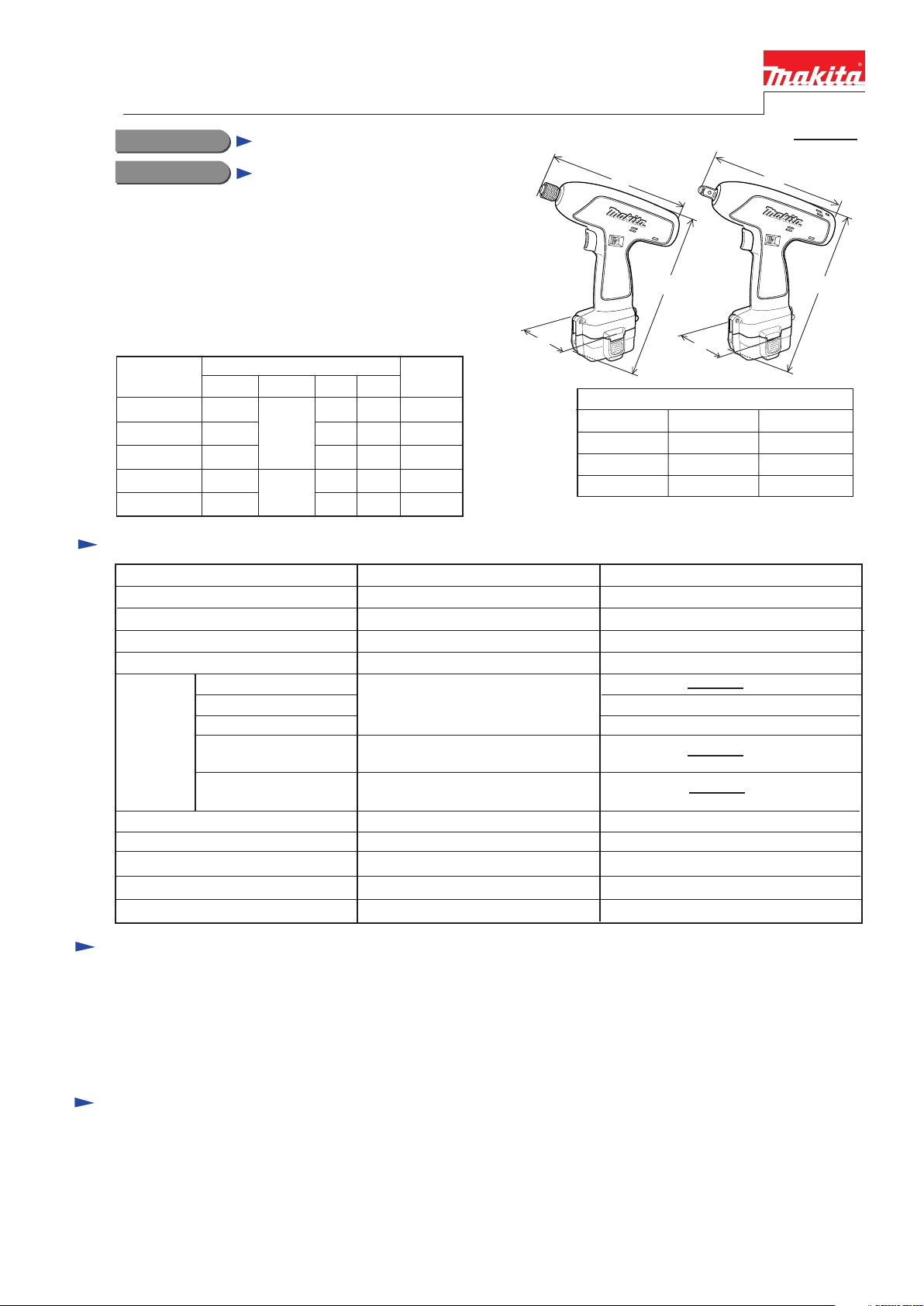
6993D
W
L
Dimensions : mm ( " )
Model No.
Width ( W )
Height ( H )
Length ( L )
NEW TOOL
P 1 / 5
L
6994D
H
W
6993D
77 (3)
228 (8-13/16)
188 (7-3/8) 185 (7-1/4)
6994D
77 (3)
228 (8-13/16)
H
Model No.
Voltage (V)
No load speed (min-1=rpm)
Impact per minute (min-1=bpm)
Driving shank : mm ( " )
Machine screw
Standard bolt
Capacities
Max. fastening torque
Reverse switch
Electric brake
Charging time with DC9710
Net weight: kg (lbs)
High Tensile bolt
Course thread: mm (")
Self drilling screw
:mm (")
M4 - M10 (5/32 - 3/8)
22 - 90 (7/8 - 3-1/2) in length
4 - 6 (5/32 - 1/4) in diameter
13 - 45 (1/2 - 1-3/4) in length
68.6 N.m (700Kgf.cm, 600 in.lbs) 68.6 N.m (700Kgf.cm, 600 in.lbs)
** approx. 60 minutes ** approx. 60 minutes
6993D
D/C 9.6
0 - 2,200
0 - 2,800
6.35 (1/4) Hex
Yes
Yes
1.3 (3.0 )
Standard equipment
For Mod.6993D
* Philips bit 2-65 .............. 1 pc.(Except North America, South America
Europe and Great Britain)
* Battery cover ................. 1 pc.
* Plastic carrying case ....... 1 pc.
< Note > The standard equipment for the tool shown may differ from country to country.
For Mod.6994D
* Battery cover ................. 1 pc.
* Plastic carrying case ....... 1 pc.
6994D
D/C 9.6
0 - 2,000
0 - 2,600
9.5 (3/8) Square
M5 - M12 (3/16 - 15/32)
M5 - M10 (3/16 - 3/8)
Yes
Yes
1.3 (3.0 )
Optional accessories
For Mod.6993D
* Various driver bits and socket bits
* Various drill chuck sets
* Bit piece
* Set plate for batteries
without set plate
* Ni-Cd Battery 9100, 9102, 9102A
and 9120
* Ni-MH Battery 9133, 9134 and 9135
* Charger DC1411 and DC1801
* Automotive charger DC1422
For Mod.6994D
* Ni-Cd Battery 9100, 9102, 9102A
and 9120
* Ni-MH Battery 9133, 9134 and 9135
* Charger DC1411 and DC1801
* Automotive charger DC1422
* Set plate for batteries without set plate
Page 2
Features and benefits
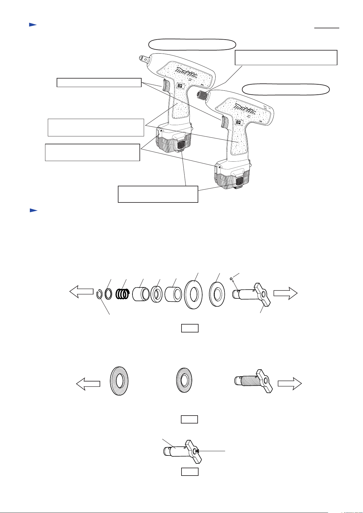
Variable speed for easier start up
Gripping angle makes bit centering
easier and operation more convenient.
Set plate can be installed for your
existing batteries of non-push button.
P 2 / 5
6994D Cordless impact wrench
Easy sleeve system for quick replacing
the bits
6993D Cordless impact driver
Push button type battery
for easy and quick replacement
Repair
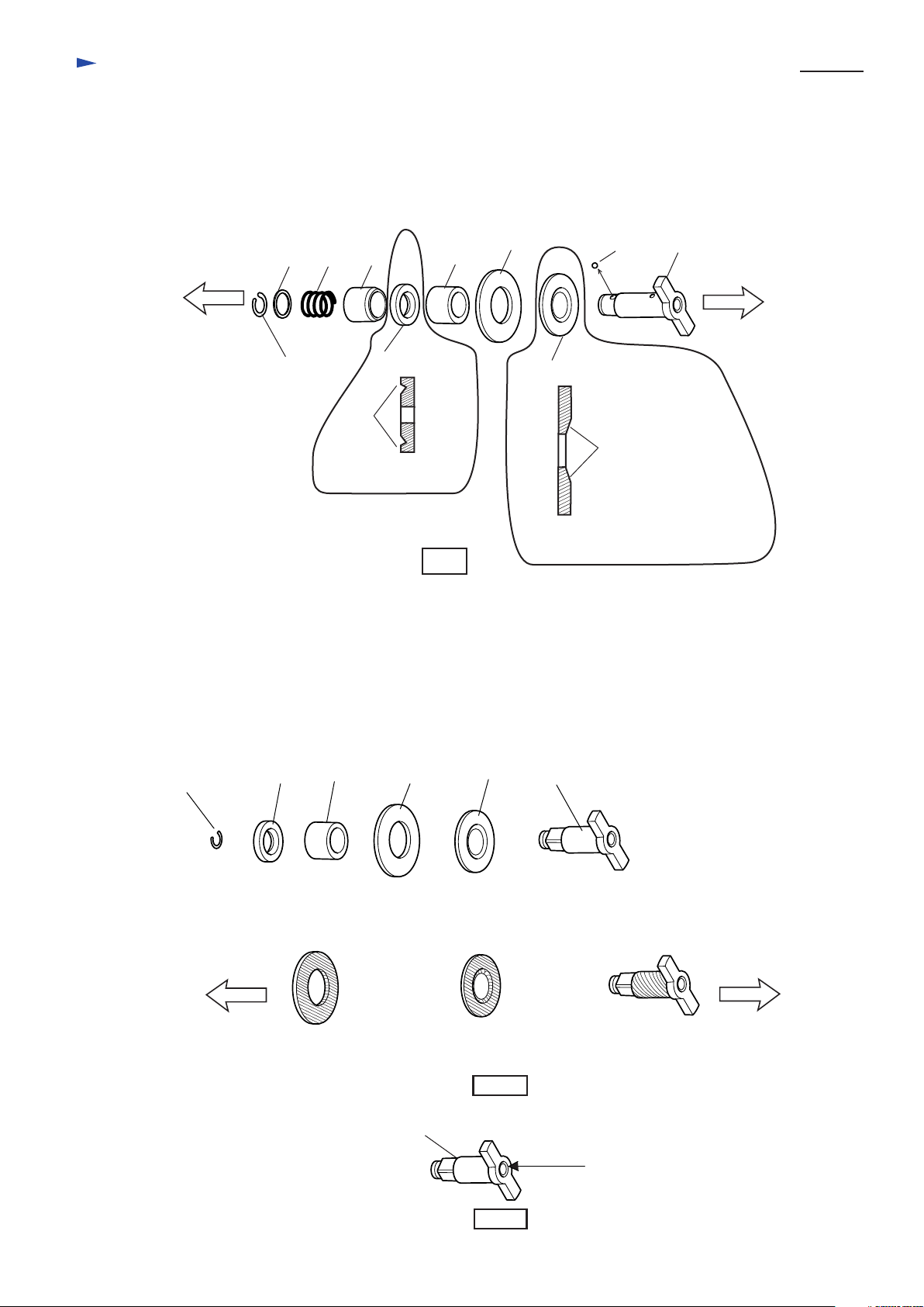
< 1 > Removing and assembling anvil section for Model 6993D
Remove ring spring 11 from the groove of anvil with retaining ring plier. Then, the following parts can be
removed from anvil. See Fig. 1.
(16) Flat washer 12
(19) Oil seal 14
(22) Nylon washer 14
Bit installing side
< Note in assembling >
1. Lubrication : Apply 0.5 g MAKITA grease N No.2 to the hatched portions illustrated in Fig. 2.
(21) Rubber sleeve 20
Bit installing side
(16) (17)
(15) Ring spring 11
(17) Compression spring 13
(20) Sleeve 14
(14) Steel ball
(18) (19) (20)
Fig. 1
(22) Nylon washer 14
(18) Sleeve
(21) Rubber washer 20
(21)
(22)
(14)
(23) Anvil
Hammer installing side
(23) Anvil
Hammer and spindle
installing side
The portion sliding
on nylon washer 14
2. Lubrication : Apply 2 g MAKITA grease N No.2 into the anvil's hole where spindle is to be assembled.
(23) Anvil
The portion on which
anvil slides.
Fig. 2
Fig. 3
The cylindric part
of anvil
Apply grease here.
Page 3
Repair
3. Assembling oil seal 14 and nylon washer 20 for Model 6993D
Oil seal 14 and nylon washer 20 have to be assembled as illustrated in Fig. 4.
P 3 / 5
Bit installing side
(15) Ring spring 11
Side view
(16) Flat washer 12
(19) Oil seal 14
(22) Nylon washer 14
(16) (17)
(18)
Lip
The lip has to be faced
to bit installing side.
(17) Compression spring 13
(20) Sleeve 14
(14) Steel ball
(20)
(19) Oil seal 14
Fig. 4
(18) Sleeve
(21) Rubber washer 20
(21)
(22) Nylon washer 14
The concave portion has to be
faced to hammer installing side.
(14)
Concave portion
(23) Anvil
Hammer installing side
< 1-A > Removing and assembling anvil section for Model 6994D
Remove ring spring 7 from the groove of anvil with retaining ring plier. Then, the following parts can be
removed from anvil. See Fig. 1A.
(15) Oil seal 14
(18) Nylon washer 14
Ring spring 7
< Note in assembling >
1. Lubrication : Apply 0.5 g MAKITA grease N No.2 to the hatched portions illustrated in Fig. 2.
Bit installing side
(15)
(21) Rubber sleeve 20
The portion sliding
on nylon washer 14
(16) Sleeve 14
(19) Anvil
(16) (17)
(17) Rubber washer 20
(18)
(22) Nylon washer 14
The portion on which
anvil slides.
Fig. 2A
(19)
(19) Anvil
The cylindric part
of anvil
Hammer and spindle
installing side
2. Lubrication : Apply 2 g MAKITA grease N No.2 into the anvil's hole where spindle is to be assembled.
(19) Anvil
Apply grease here.
Fig. 3A
Page 4
Repair
P 4 / 5
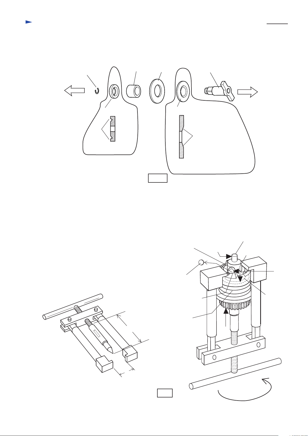
3. Assembling oil seal 14 and nylon washer 20 for Model 6994D
Oil seal 14 and nylon washer 20 have to be assembled as illustrated in Fig. 4A.
(15) Oil seal 14
(18) Nylon washer 14
Ring spring 7
Bit installing side
(15) Oil seal 14
Lip
The lip has to be faced
to bit installing side.
< 2 > Removing hammer
(1) Press down hammer with 1R045: Large gear extractor
by turning the handle.
(2)Adjust the opening for steel ball inserting to the cam groove top of spindle.
(3)Take off steel ball 5.6 from spindle.
(4)Apply MAKITA grease N No.2 each 0.5 g to the position No. (1) - (4) in Fg. 5.
(16) Sleeve 14
(19) Anvil
(16) (17)
Fig. 4A
(17) Rubber washer 20
(18) Nylon washer 14
The concave portion has to be
faced to hammer installing side.
(19)
Hammer installing side
Concave portion
1R045 Large gear extractor
L= 85mm
L=105mm
L=130mm
W: The maximum opening width
is 170mm.
Steel ball 5.6 x 2 pcs.
Compression spring 24
L
W
Cam groove top
of spindle
Opening for steel
ball inserting
Fig. 5
Spindle
(1)
(2)
(3)
Hammer
(4)
Page 5
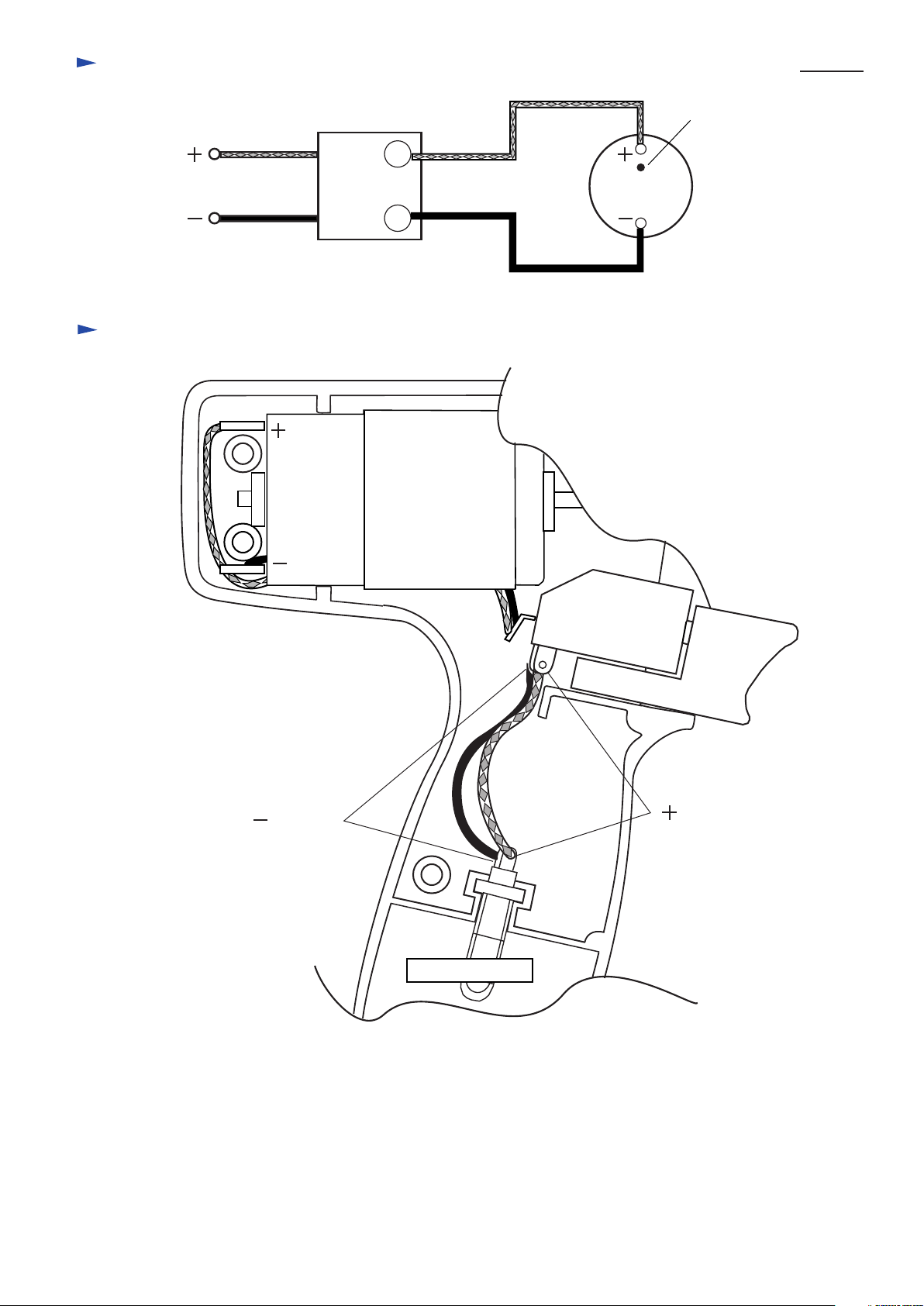
Circuit diagram
P 5 / 5
Red point
T
Battery holder
T
Wiring diagram
Switch
Terminal
Terminal
M1
M2
DC motor
Red
Black
DC motor
Lead wire (black)
Terminal
Variable speed
control switch
Lead wire (red)
Terminal
Battery holder
 Loading...