

Page 1
GB
Cordless Impact Wrench Instruction Manual
F
Boulonneuse sans fil Manuel d’instructions
D Akku-Schlagschrauber
I
Avvitatrice ad impulso a batteria
NL Snoerloze slagmoersleutel
E Llave de impacto a batería
P Chave de impacto a bateria
DK Elektronisk akku slagnøgle
S Sladdlös mutterdragare
N Batteridrevet slagskrunøkkel
SF Akku-iskuväännin
GR Ασύρµατο κρουστικ Οδηγίες χρήσεως
Betriebsanleitung
Istruzioni per l’uso
Gebruiksaanwijzing
Manual de instrucciones
Manual de instruções
Brugsanvisning
Bruksanvisning
Bruksanvisning
Käyttöohje
6915D
Page 2
4
1
3
5
2
12
6
7
34
Kg.cm
1000
8
800
600
400
200
0
M12X45
M10X45
1234
9
M14X45
11
11
11
10
M14
M12
M10
Kg.cm
8
1200
1000
800
600
400
200
0
1234 56
9
M8X45
M12X50
M10X45
11
11
11
M12
M10
M8
10
56
2
Page 3

ENGLISH
1 Push button
2 Battery cartridge
3 O-ring
4 Socket
Explanation of general view
5Pin
6 Switch trigger
7 Reversing switch
8 Fastening torque
9 Fastening time
10 Seconds
11 Proper fastening torque for
SPECIFICATIONS
Model 6915D
Capacities
Standard bolt ............................................... M8 – M14
High tensile bolt ........................................... M6 – M12
Square drive ..................................................... 12.7 mm
No load speed (min
Impacts per minute .......................................... 0 – 2,500
Max. fastening torque ....................................... 117 N•m
Overall length .................................................... 221 mm
Net weight (with battery cartridge) ....................... 1.9 kg
Rated voltage .................................................. D.C. 12 V
• Due to our continuing program of research and deve-
lopment, the specifications herein are subject to
change without notice.
• Note: Specifications may differ from country to country.
Intended use
The tool is intended for fastening bolts and nuts.
Safety Hints
For your own safety, please refer to the enclosed safety
instructions.
–1
) ..................................... 0 – 1,800
IMPORTANT SAFETY INSTRUCTIONS FOR
CHARGER & BATTERY CARTRIDGE
1. Before using battery cartridge, read all instruc-
tions and cautionary markings on (1) battery
charger, (2) battery, and (3) product using battery.
2. Do not disassemble battery cartridge.
3. If operating time has become excessively
shorter, stop operating immediately. It may
result in a risk of overheating, possible burns
and even an explosion.
4. If electrolyte gets into your eyes, rinse them out
with clear water and seek medical attention right
away. It may result in loss of your eyesight.
5. Always cover the battery terminals with the bat-
tery cover when the battery cartridge is not
used.
6. Do not short the battery cartridge:
(1) Do not touch the terminals with any conduc-
tive material.
(2) Avoid storing battery cartridge in a container
with other metal objects such as nails, coins,
etc.
(3) Do not expose battery cartridge to water or
rain.
A battery short can cause a large current flow,
overheating, possible burns and even a breakdown.
7. Do not store the tool and battery cartridge in
locations where the temperature may reach or
exceed 50°C (122°F).
ENC004-1
8. Do not incinerate the battery cartridge even if it
is severely damaged or is completely worn out.
The battery cartridge can explode in a fire.
9. Be careful not to drop or strike battery.
SAVE THESE INSTRUCTIONS.
Tips for maintaining maximum battery life
1. Charge the battery cartridge before completely
discharged.
Always stop tool operation and charge the battery cartridge when you notice less tool power.
2. Never recharge a fully charged battery cartridge.
Overcharging shortens the battery service life.
3. Charge the battery cartridge with room temperature at 10°C – 40°C (50°F – 104°F). Let a hot battery cartridge cool down before charging it.
4. Charge the Nickel Metal Hydride battery cartridge when you do not use it for more than six
months.
ADDITIONAL SAFETY RULES FOR TOOL
1. Be aware that this tool is always in an operating
condition, because it does not have to be
plugged into an electrical outlet.
2. Hold tool by insulated gripping surfaces when
performing an operation where the cutting tool
may contact hidden wiring. Contact with a “live”
wire will also make exposed metal parts of the
tool “live” and shock the operator.
3. Wear ear protectors.
4. Check the socket carefully for wear, cracks or
damage before installation.
5. Hold the tool firmly.
6. Always be sure you have a firm footing.
7. Be sure no one is below when using the tool in
high locations.
8. The proper fastening torque may differ depending upon the kind or size of the bolt. Check the
torque with a torque wrench.
ENB025-1
SAVE THESE INSTRUCTIONS.
3
Page 4

OPERATING INSTRUCTIONS
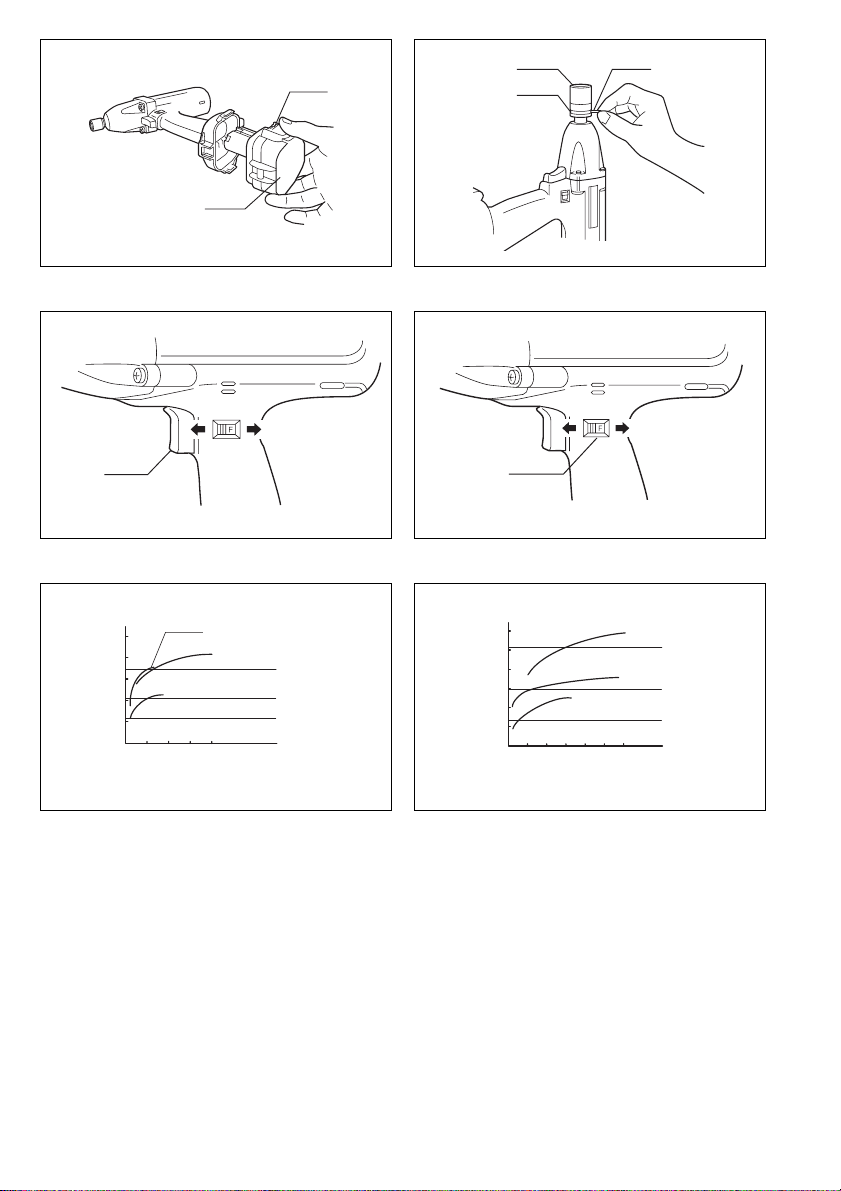
Installing or removing battery cartridge (Fig. 1)
• Always switch off the tool before insertion or removal of
the battery cartridge.
• To remove the battery cartridge, withdraw it from the
tool while pressing the push buttons on both sides of
the cartridge.
• To insert the battery cartridge, align the tongue on the
battery cartridge with the groove in the housing and slip
it into place. Always insert it all the way until it locks in
place with a little click. If not, it may accidentally fall out
of the tool, causing injury to you or someone around
you.
• Do not use force when inserting the battery cartridge. If
the cartridge does not slide in easily, it is not being
inserted correctly.
Selecting correct socket
Always use the correct size socket for bolts and nuts. An
incorrect size socket will result in inaccurate and inconsistent fastening torque and/or damage to the bolt or nut.
Installing or removing socket (Fig. 2)
Important:
Always be sure that the tool is switched off and the battery cartridge is removed before installing or removing
the socket.
Move the O-ring out of the groove in the socket and
remove the pin from the socket. Fit the socket onto the
anvil of the tool so that the hole in the socket is aligned
with the hole in the anvil. Insert the pin through the hole
in the socket and anvil. Then return the O-ring to the original position in the socket groove to retain the pin. To
remove the socket, follow the installation procedures in
reverse.
Switch action (Fig. 3)
CAUTION:
Before inserting the battery cartridge into the tool, always
check to see that the switch trigger actuates properly and
returns to the “OFF” position when released.
To start the tool, simply pull the trigger. Tool speed is
increased by increasing pressure on the trigger. Release
the trigger to stop.
Reversing switch action (Fig. 4)
CAUTION:
• Always check the direction of rotation before operation.
• Use the reversing switch only after the tool comes to a
complete stop. Changing the direction of rotation
before the tool stops may damage the tool.
This tool has a reversing switch to change the direction
of rotation. Slide the reversing switch to the left for
clockwise rotation or to the right for counterclockwise
rotation.
Operation (Fig. 5 & 6)
The proper fastening torque may differ depending upon
the kind or size of the bolt. The relation between fastening torque and fastening time is shown in the figures.
Hold the tool firmly and place the socket over the bolt or
nut. Turn the tool on and fasten for the proper fastening
time.
NOTE:
• Hold the tool pointed straight at the bolt or nut without
applying excessive pressure on the tool.
• Excessive fastening torque may damage the bolt or
nut. Before starting your job, always perform a test
operation to verify the adequate fastening speed and
time for your bolt or nut.
The fastening torque is affected by a wide variety of
factors including the following. After fastening, always
check the torque with a torque wrench.
1. When the battery cartridge is discharged almost
completely, voltage will drop and the fastening
torque will be reduced.
2. Socket
• Failure to use the correct size socket will cause a
reduction in the fastening torque.
• A worn socket (wear on the hex end or square
end) will cause a reduction in the fastening
torque.
3. Bolt
• Even though the torque coefficient and the class
of bolt are the same, the proper fastening torque
will differ according to the diameter of the bolt.
• Even though the diameters of bolts are the same,
the proper fastening torque will differ according to
the torque coefficient, the class of bolt and the
bolt length.
4. The use of the universal joint or the extension bar
somewhat reduces the fastening force of the impact
wrench. Compensate by fastening for a longer
period of time.
5. Type of materials to be fastened, the manner of holding the tool and the tool speed will affect the torque.
CAUTION:
If the tool is operated continuously until the battery cartridge has discharged, allow the tool to rest for 15 minutes
before proceeding with a fresh battery.
MAINTENANCE
CAUTION:
Always be sure that the tool is switched off and the battery cartridge is removed before carrying out any work on
the tool.
To maintain product safety and reliability, repairs, maintenance or adjustment should be carried out by a Makita
Authorized Service Center.
ACCESSORIES
CAUTION:
• These accessories or attachments are recommended
for use with your Makita tool specified in this manual.
The use of any other accessories or attachments might
present a risk of injury to persons. Only use accessory
or attachment for its stated purpose.
If you need any assistance for more details regarding
these accessories, ask your local Makita service center.
• Socket (with pin and O-ring)
• Extension bar (with pin and O-ring)
• Universal joint (with pin and O-ring)
• Bit adapter (with pin and O-ring)
• Phillips bit
• Various type of Makita genuine batteries and chargers
• Plastic carrying case
4
Page 5

NEDERLANDS
1 Knop
2 Accu
3O-ring
4Sok
Verklaring van algemene gegevens
5 Pen
6 Trekschakelaar
7 Omkeerschakelaar
8 Aantrekkoppel
9 Aantrektijd
10 Seconden
11 Juist aantrekkoppel voor
TECHNISCHE GEGEVENS
Model 6915D
Capaciteiten
Standaardbout ............................................. M8 – M14
Trekvaste bout ............................................. M6 – M12
Vierkant ............................................................ 12,7 mm
Toerental onbelast (min
Aantal slagen per minuut ................................. 0 – 2 500
Maximaal aantrekkoppel .................................. 117 N•m
Totale lengte ...................................................... 221 mm
Netto gewicht (accu inbegrepen) .......................... 1,9 kg
Nominale spanning ......................................... D.C. 12 V
• In verband met ononderbroken research en ontwikke-
ling behouden wij ons het recht voor bovenstaande
technische gegevens te wijzigen zonder voorafgaande
kennisgeving.
• Opmerking: De technische gegevens kunnen van land
tot land verschillen.
Doeleinden van gebruik
Dit gereedschap is bedoeld voor het vastdraaien van
bouten en moeren.
Veiligheidswenken
Volg veiligheidshalve de bijgevoegde veiligheidsvoorschriften nauwkeurig op.
–1
) ............................... 0 – 1 800
BELANGRIJKE
VEILIGHEIDSVOORSCHRIFTEN VOOR
ACCULADER EN ACCU
1. Lees alle voorschriften en waarschuwingen op
(1) de acculader, (2) de accu, en (3) het product
waarvoor de accu wordt gebruikt, aandachtig
door alvorens de acculader in gebruik te nemen.
2. Neem de accu niet uit elkaar.
3. Als de gebruikstijd van een opgeladen accu aan-
zienlijk korter is geworden, moet u het gebruik
ervan onmiddellijk stopzetten. Voortgezet
gebruik kan oververhitting, brandwonden en
zelfs een ontploffing veroorzaken.
4. Als er elektrolyt in uw ogen is terechtgekomen,
spoel dan uw ogen met schoon water en roep
onmiddellijk de hulp van een dokter in. Elektrolyt
in de ogen kan blindheid veroorzaken.
5. Bedek de accuklemmen altijd met de accukap
wanneer u de accu niet gebruikt.
6. Voorkom kortsluiting van de accu:
(1) Raak de accuklemmen nooit aan met een
geleidend materiaal.
(2) Bewaar de accu niet in een bak waarin
andere metalen voorwerpen zoals spijkers,
munten e.d. worden bewaard.
(3) Stel de accu niet bloot aan water of regen.
Kortsluiting van de accu kan oorzaak zijn van
een grote stroomafgifte, oververhitting, brandwonden, en zelfs defecten.
7. Bewaar het gereedschap en de accu niet op
plaatsen waar de temperatuur kan oplopen tot
50°C of hoger.
8. Werp de accu nooit in het vuur, ook niet wanneer
hij zwaar beschadigd of volledig versleten is. De
accu kan namelijk ontploffen in het vuur.
9. Wees voorzichtig dat u de accu niet laat vallen
en hem niet blootstelt aan schokken of stoten.
BEWAAR DEZE VOORSCHRIFTEN.
Tips voor een maximale levensduur van de accu
1. Laad de accu op voordat hij volledig ontladen is.
Stop het gebruik van het gereedschap en laad de
accu op telkens wanneer u vaststelt dat het vermogen van het gereedschap is afgenomen.
2. Laad een volledig opgeladen accu nooit opnieuw
op. Als u de accu te veel oplaadt, zal hij minder
lang meegaan.
3. Laad de accu op bij een kamertemperatuur tussen 10°C en 40°C. Laat een warme accu afkoelen
alvorens hem op te laden.
4. Laad de nikkel-metaalhydride accu op telkens
wanneer u hem langer dan zes maanden niet
hebt gebruikt.
AANVULLENDE
VEILIGHEIDSVOORSCHRIFTEN VOOR HET
GEREEDSCHAP
1. Denk eraan dat dit gereedschap altijd gebruiksklaar is, aangezien het niet op een stopcontact
hoeft te worden aangesloten.
2. Houd het gereedschap bij de geïsoleerde handgrepen vast wanneer u boort op plaatsen waar
de boor op verborgen elektrische bedrading kan
stoten. Door contact met een onder spanning
staande draad zullen ook de niet-geïsoleerde
metalen delen van het gereedschap onder spanning komen te staan, zodat de gebruiker een
elektrische schok kan krijgen.
3. Draag oorbeschermers.
4. Controleer de sok nauwkeurig op slijtage,
scheuren of beschadiging alvorens deze op het
gereedschap te monteren.
5. Houd het gereedschap stevig vast.
6. Zorg ervoor dat u altijd stevige steun voor de
voeten hebt.
7. Controleer of er niemand beneden u aanwezig is
wanneer u het gereedschap op een hoge plaats
gaat gebruiken.
8. Het juiste aantrekkoppel kan verschillen afhankelijk van de soort of grootte van de bout. Controleer het aantrekkoppel met een
momentsleutel.
BEWAAR DEZE VOORSCHRIFTEN.
14
Page 6

BEDIENINGSVOORSCHRIFTEN
Installeren of verwijderen van de accu (Fig. 1)
• Schakel het gereedschap altijd uit alvorens de accu te
installeren of te verwijderen.
• Om de accu te verwijderen, neemt u deze uit het
gereedschap terwijl u de knoppen aan beide zijden van
de accu indrukt.
• Om de accu te installeren, past u de tong op de accu in
de groef in de houder, en dan schuift u de accu erin.
Schuif de accu zo ver mogelijk erin, totdat deze met
een klikgeluid vergrendelt. Indien u dit niet doet, kan de
accu per ongeluk uit het gereedschap vallen en uzelf of
anderen verwonden.
• Als de accu moeilijk in de houder gaat, moet u niet proberen hem met geweld erin te duwen. Indien de accu
er niet gemakkelijk ingaat, betekent dit dat u hem niet
op de juiste wijze erin steekt.
Selecteren van de juiste sok
Gebruik altijd een sok van de juiste maat voor het vastdraaien van bouten en moeren. Het gebruik van een sok
van de onjuiste maat zal een onnauwkeurig of onregelmatig aantrekkoppel en/of beschadiging van de bout of
moer tot gevolg hebben.
Installeren of verwijderen van de sok (Fig. 2)
Belangrijk:
Controleer altijd of het gereedschap is uitgeschakeld en
de accu is verwijderd alvorens de sok te installeren of te
verwijderen.
Verwijder de O-ring uit de groef in de sok en verwijder de
pen uit de sok. Schuif de sok over het draaistuk van het
gereedschap zodat het gat in de sok op één lijn komt met
het gat in het draaistuk. Steek de pen door het gat in de
sok en in het draaistuk. Breng de O-ring weer op zijn oorspronkelijke plaats in de groef aan, zodat de pen op zijn
plaats wordt gehouden. Om de sok te verwijderen, voert
u deze procedure in omgekeerde volgorde uit.
Werking van de trekschakelaar (Fig. 3)
LET OP:
Alvorens de accu in het gereedschap te plaatsen, moet u
altijd controleren of de trekschakelaar juist werkt en bij
loslaten naar de “OFF” positie terugkeert.
Om het gereedschap te starten, drukt u gewoon de trekschakelaar in. Oefen meer druk uit op de trekschakelaar
om het toerental te vermeerderen. Om het gereedschap
te stoppen, de trekschakelaar loslaten.
Werking van de omkeerschakelaar (Fig. 4)
LET OP:
• Controleer altijd de draairichting alvorens het gereedschap te gebruiken.
• Verander de stand van de omkeerschakelaar pas
nadat het gereedschap volledig tot stilstand is gekomen. Indien u de draairichting verandert terwijl het
gereedschap nog draait, kan het gereedschap beschadigd raken.
Dit gereedschap heeft een omkeerschakelaar voor het
veranderen van de draairichting. Schuif de omkeerschakelaar naar links voor rechtse draairichting, of naar
rechts voor linkse draairichting.
Bediening (Fig. 5 en 6)
Het juiste aantrekkoppel voor de bout hangt af van de
soort of grootte van de bout. De verhouding tussen het
aantrekkoppel en de aantrektijd is op de grafieken aangegeven.
Houd het gereedschap stevig vast en plaats de sok over
de bout of moer. Schakel het gereedschap in en draai de
bout of moer in de juiste aantrektijd vast.
OPMERKING:
• Plaats het gereedschap recht op de bout of moer en
zorg ervoor dat u niet te veel druk op het gereedschap
uitoefent.
• Een te groot aantrekkoppel kan de bout of moer
beschadigen. Alvorens het eigenlijke werk te doen,
moet u daarom altijd een proefje doen met een gelijke
bout of moer voor het vaststellen van de juiste aantreksnelheid en aantrektijd.
Het aantrekkoppel wordt beïnvloed door een aantal verschillende factoren, waaronder de volgende. Controleer
na het vastdraaien altijd het aantrekkoppel met een
momentsleutel.
1. Wanneer de accu bijna leeg is, neemt het voltage af
en vermindert het aantrekkoppel.
2. Sok
• Het gebruik van een sok van de onjuiste maat zal
resulteren in een te laag aantrekkoppel.
• Een versleten sok (slijtage op het zeskante of vierkante uiteinde) zal resulteren in een te laag aantrekkoppel.
3. Bout
• Zelfs wanneer de koppelverhouding en de klasse
van de bout overeenkomen, kan door verschillen
in de diameter van de bouten het juiste aantrekkoppel per bout toch afwijken.
• Ook al zijn de diameters van twee bouten gelijk,
dan kunnen er nog verschillen in het juiste aantrekkoppel van de twee bouten optreden ten
gevolge van verschillen in de koppelverhouding en
de klasse en lengte van de bouten.
4. Het aantrekkoppel is iets lager wanneer een kogelgewrichtverbinding of verlengstaaf wordt gebruikt. U
kunt dit verlies aan aantrekkoppel compenseren
door de aantrektijd te verlengen.
5. Het materiaal van de vast te draaien bout of moer,
de manier van vasthouden van het gereedschap en
het toerental hebben invloed op het aantrekkoppel.
LET OP:
Indien u het gereedschap zonder onderbreking gebruikt
totdat de accu is uitgeput, dient u het gereedschap 15
minuten te laten rusten alvorens met een verse accu verder te werken.
ONDERHOUD
LET OP:
Controleer altijd of het gereedschap is uitgeschakeld en
de accu is losgekoppeld vooraleer onderhoud uit te voeren aan het gereedschap.
Opdat het gereedschap veilig en betrouwbaar blijft, dienen alle reparaties, onderhoud of afstellingen te worden
uitgevoerd bij een erkend Makita service centrum.
15
Page 7

ACCESSOIRES
LET OP:
• Deze accessoires of hulpstukken worden aanbevolen
voor gebruik met het Makita gereedschap dat in deze
gebruiksaanwijzing is beschreven. Bij gebruik van
andere accessoires of hulpstukken bestaat er gevaar
voor persoonlijke verwonding. Gebruik de accessoires
of hulpstukken uitsluitend voor hun bestemde doel.
Raadpleeg het dichtstbijzijnde Makita Servicecentrum
voor verder advies of bijzonderheden omtrent deze
accessoires.
• Sok (met pen en O-ring)
• Verlengstaaf (met pen en O-ring)
• Aantrekkoppel (met pen en O-ring)
• Bitadapter (met pen en O-ring)
• Phillips schroefbit
• Diverse types originele Makita accu’s en acculaders
• Plastic draagkoffer
16
Page 8

ENGLISH
EC-DECLARATION OF CONFORMITY
The undersigned, Yasuhiko Kanzaki, authorized by Makita
Corporation, 3-11-8 Sumiyoshi-Cho, Anjo, Aichi 446-8502
Japan declares that this product
manufactured by Makita Corporation in Japan is in compliance with the following standards or standardized documents,
in accordance with Council Directives, 89/336/EEC and
98/37/EC.
(Serial No. : series production)
EN50260, EN55014,
FRANÇAISE
DÉCLARATION DE CONFORMITÉ CE
Je soussigné, Yasuhiko Kanzaki, mandaté par Makita Corporation, 3-11-8 Sumiyoshi-Cho, Anjo, Aichi 446-8502
Japan, déclare que ce produit
fabriqué par Makita Corporation au Japon, est conformes
aux normes ou aux documents normalisés suivants,
conformément aux Directives du Conseil, 89/336/CEE et
98/37/EG.
(No. de série: production en série)
EN50260, EN55014,
DEUTSCH
Hiermit erklärt der Unterzeichnete, Yasuhiko Kanzaki,
Bevollmächtigter von Makita Corporation, 3-11-8
Sumiyoshi-Cho, Anjo, Aichi 446-8502 Japan, daß dieses von der Firma Makita Corporation in Japan hergestellte Produkt
gemäß den Ratsdirektiven 89/336/EWG und 98/37/EG
mit den folgenden Normen bzw. Normendokumenten
übereinstimmen:
CE-KONFORMITÄTSERKLÄRUNG
(Serien-Nr.: Serienproduktion)
EN50260, EN55014.
ITALIANO
DICHIARAZIONE DI CONFORMITÀ CON LE NORME
Il sottoscritto Yasuhiko Kanzaki, con l’autorizzazione
della Makita Corporation, 3-11-8 Sumiyoshi-Cho, Anjo,
Aichi 446-8502 Japan, dichiara che questo prodotto
fabbricato dalla Makita Corporation in Giappone è conformi alle direttive europee riportate di seguito:
secondo le direttive del Consiglio 89/336/CEE e 98/37/CE.
DELLA COMUNITÀ EUROPEA
(Numero di serie: Produzione in serie)
EN50260, EN55014
NEDERLANDS
EG-VERKLARING VAN CONFORMITEIT
De ondergetekende, Yasuhiko Kanzaki, gevolmachtigd
door Makita Corporation, 3-11-8 Sumiyoshi-Cho, Anjo,
Aichi 446-8502 Japan verklaart dat dit produkt
vervaardigd door Makita Corporation in Japan voldoet
aan de volgende normen of genormaliseerde documenten,
in overeenstemming met de richtlijnen van de Raad
89/336/EEC en 98/37/EC.
(Serienr. : serieproduktie)
EN50260, EN55014
ESPAÑOL
DECLARACIÓN DE CONFORMIDAD DE LA CE
El abajo firmante, Yasuhiko Kanzaki, autorizado por
Makita Corporation, 3-11-8 Sumiyoshi-Cho, Anjo, Aichi
446-8502 Japan, declara que este producto
(Número de serie: producción en serie)
fabricado por Makita Corporation en Japón cumple las
siguientes normas o documentos normalizados,
de acuerdo con las directivas comunitarias, 89/336/EEC
y 98/37/CE.
EN50260, EN55014
Yasuhiko Kanzaki
Director Amministratore
Directeur Directeur
Direktor Director
CE 99
MAKITA INTERNATIONAL EUROPE LTD.
Michigan Drive, Tongwell, Milton Keynes,
Bucks MK15 8JD, ENGLAND
35
Page 9

PORTUGUÊS
DECLARAÇÃO DE CONFORMIDADE DA CE
O abaixo assinado, Yasuhiko Kanzaki, autorizado pela
Makita Corporation, 3-11-8 Sumiyoshi-Cho, Anjo, Aichi
446-8502 Japan, declara que este produto
fabricado pela Makita Corporation no Japão obedece às
seguintes normas ou documentos normalizados,
de acordo com as directivas 89/336/CEE e 98/37/CE do
Conselho.
(N. de série: produção em série)
EN50260, EN55014
NORSK
Undertegnede, Yasuhiko Kanzaki, med fullmakt fra
Makita Corporation, 3-11-8 Sumiyoshi-Cho, Anjo, Aichi
446-8502 Japan bekrefter herved at dette produktet
fabrikert av Makita Corporation, Japan, er i overensstemmelse med følgende standarder eller standardiserte
dokumenter:
i samsvar med Råds-direktivene, 89/336/EEC og 98/37/EC.
EUs SAMSVARS-ERKLÆRING
(Serienr. : serieproduksjon)
EN50260, EN55014,
DANSK
EU-DEKLARATION OM KONFORMITET
Undertegnede, Yasuhiko Kanzaki, med fuldmagt fra
Makita Corporation, 3-11-8 Sumiyoshi-Cho, Anjo, Aichi
446-8502 Japan, erklærer hermed, at dette produkt
fremstillet af Makita Corporation i Japan, er i overens-
(Løbenummer: serieproduktion)
stemmelse med de følgende standarder eller normsættende dokumenter,
EN50260, EN55014
i overensstemmelse med Rådets Direktiver 89/336/EEC
og 98/37/EC.
SVENSKA
EG-DEKLARATION OM ÖVERENSSTÄMMELSE
Undertecknad, Yasuhiko Kanzaki, auktoriserad av
Makita Corporation, 3-11-8 Sumiyoshi-Cho, Anjo,
Aichi 446-8502 Japan deklarerar att denna produkt
tillverkad av Makita Corporation i Japan, uppfyller kraven
i följande standard eller standardiserade dokument,
i enlighet med EG-direktiven 89/336/EEC och 98/37/EC.
(serienummer: serieproduktion)
EN50260, EN55014
SUOMI
VAKUUTUS EC-VASTAAVUUDESTA
Makita Corporation, 3-11-8 Sumiyoshi-Cho, Anjo, Aichi
446-8502 Japan valtuuttamana allekirjoittanut, Yasuhiko
Kanzaki, vakuuttaa että tämä tämä tuote
(Sarja nro : sarjan tuotantoa)
valmistanut Makita Corporation Japanissa vastaa seuraavia standardeja tai stardardoituja asiakirjoja
EN50260, EN55014
neuvoston direktiivien 89/336/EEC ja 98/37/EC mukaisesti.
ΕΛΛΗΝΙΚΑ
Ο υπογράφων, Yasuhiko Kanzaki, εξουσιοδοτηµένος
απ την εταιρεία Makita Corporation, 3-11-8
Sumiyoshi-Cho, Anjo, Aichi 446-8502 Japan, δηλώνει
τι αυτ το προϊν
κατασκευασµένο απ την Εταιρεία Makita στην
Ιαπωνία, βρίσκεται σε συµφωνία µε τα ακλουθα
πρτυπα ή τυποποιηµένα έγγραφα,
σύµφωνα µε τις Οδηγίες του Συµβουλίου, 89/336/EEC
και 98/37/KE.
∆ΗΛΩΣΗ ΣΥΜΜΟΡΦΩΣΗΣ ΕΚ
(Αύξων Αρ.: παραγωγή σειράς)
EN50260, EN55014
36
Yasuhiko Kanzaki
CE 99
Director Direktor
Direktør Johtaja
Direktör ∆ιευθυντής
MAKITA INTERNATIONAL EUROPE LTD.
Michigan Drive, Tongwell, Milton Keynes,
Bucks MK15 8JD, ENGLAND
Page 10

ENGLISH
The typical A-weighted noise levels are
The typical weighted root mean square acceleration
value is 6 m/s
Noise and Vibration
sound pressure level: 93 dB (A)
sound power level: 106dB (A)
– Wear ear protection. –
2
.
FRANÇAISE
Les niveaux de bruit pondérés A types sont:
niveau de pression sonore: 93 dB (A)
niveau de puissance du son: 106 dB (A)
Bruit et vibrations
– Porter des protecteurs anti-bruit. –
L’accélération pondérée est de 6 m/s
2
.
DEUTSCH
Geräusch- und Vibrationsentwicklung
Die typischen A-bewerteten Geräuschpegel betragen:
Schalldruckpegel: 93 dB (A)
Schalleistungspegel: 106 dB (A)
– Gehörschutz tragen. –
Der gewichtete Effektivwert der Beschleunigung beträgt
2
.
6m/s
ITALIANO
I livelli del rumore pesati secondo la curva A sono:
Il valore quadratico medio di accellerazione è di 6 m/s
Rumore e vibrazione
Livello pressione sonora: 93 dB (A)
Livello potenza sonora: 106 dB (A)
– Indossare i paraorecchi. –
2
NEDERLANDS
De typische A-gewogen geluidsniveau’s zijn
De typische gewogen effectieve versnellingswaarde is
2
6m/s
Geluidsniveau en trilling
geluidsdrukniveau: 93 dB (A)
geluidsenergie-niveau: 106 dB (A)
– Draag oorbeschermers. –
.
ESPAÑOL
Los niveles típicos de ruido ponderados A son
El valor ponderado de la aceleración es de 6 m/s
Ruido y vibración
presión sonora: 93 dB (A)
nivel de potencia sonora: 106 dB (A)
– Póngase protectores en los oídos. –
2
.
PORTUGUÊS
Os níveis normais de ruído A são
O valor médio da aceleração é 6 m/s
Ruído e vibração
nível de pressão de som: 93 dB (A)
nível do sum: 106 dB (A)
– Utilize protectores para os ouvidos –
2
.
DANSK
De typiske A-vægtede lydniveauer er
Den vægtede effektive accelerationsværdi er 6 m/s
Lyd og vibration
lydtryksniveau: 93 dB (A)
lydeffektniveau: 106 dB (A)
– Bær høreværn. –
SVENSKA
De typiska A-vägda bullernivåerna är
Det typiskt vägda effektivvärdet för acceleration är
2
.
6m/s
Buller och vibration
ljudtrycksnivå: 93 dB (A)
ljudeffektnivå: 106 dB (A)
– Använd hörselskydd –
NORSK
De vanlige A-belastede støynivå er
.
Den vanlig belastede effektiv-verdi for akselerasjon er
2
.
6m/s
Støy og vibrasjon
lydtrykksnivå: 93 dB (A)
lydstyrkenivå: 106dB (A)
– Benytt hørselvern. –
SUOMI
Tyypilliset A-painotetut melutasot ovat
Tyypillinen kiihtyvyyden painotettu tehollisarvo on
2
.
6m/s
melutaso ja tärinä
äänenpainetaso: 93 dB (A)
äänen tehotaso: 106 dB (A)
– Käytä kuulosuojaimia. –
ΕΛΛΗΝΙΚΑ
Οι τυπικές A-µετρούµενες εντάσεις ήχου είναι
Η τυπική αξία της µετρούµενης ρίζας του µέσου
τετραγώνου της επιτάχυνσης είναι 6 m/s
Θρυβος και κραδασµς
πίεση ήχου: 93dB (A)
δύναµη του ήχου: 106dB (A)
– Φοράτε ωτοασπίδες. –
2
.
2
.
37
Page 11

38
Page 12

39
Page 13

Makita Corporation
884287D997
 Loading...