

Page 1
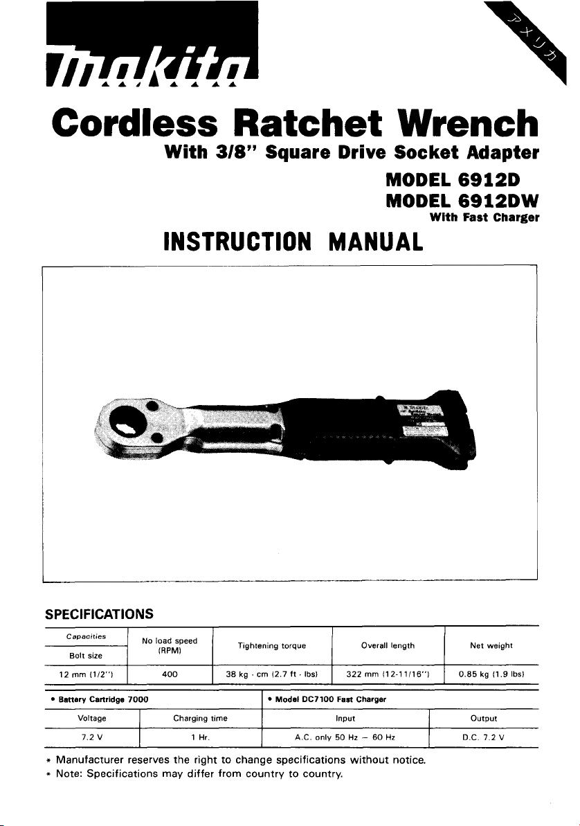
Cordless
With
Ratchet
318’’
Square
Wrench
Drive Socket Adapter
MODEL 6912D
MODEL
6912DW
With Fast Charger
SPECIFICATIONS
Capacities
7
Bolt size
12
mm
(112’’)
No
I
INSTRUCTION
load speed
IRPMI
400
1
Tightening torque Overall length Net weight
I
38 kg
.
cm
12.7 ft
.
Ibsl I 322
MANUAL
mm
I12-11/16”1
I
0.85 kg 11.9
Ibsl
Battery Cartridge 7000
Voltage
7.2 V
I
Charging time
1
Hr.
I
I
Model
DC7100 Fast Charger
Input
A.C.
only 50
Hz
I
-
60
Hz
output
D.C.
7.2 V
Page 2
IMPORTANT
SAFETY
WARNING:
WHEN USING ELECTRIC TOOLS, BASIC SAFE-
INSTRUCTIONS
(For
All Tools)
TY PRECAUTIONS SHOULD ALWAYS BE FOLLOWED
REDUCE THE RISK OF FIRE, ELECTRIC SHOCK, AND
PER-
SONAL INJURY, INCLUDING THE FOLLOWING:
READ ALL INSTRUCTIONS.
1.
KEEP WORK AREA CLEAN. Cluttered areas and benches invite injuries.
2.
CONSIDER WORK AREA ENVIRONMENT. Don't use power tools in damp
or wet locations. Keep work area well
Don't use tool in presence of flammable liquids or gases.
3.
KEEP CHILDREN AWAY. All visitors should be kept away from work area.
Don't let visitors contact tool or extension cord.
4.
STORE
or locked-up place
5.
DON'T FORCE TOOL.
it
6.
USE RIGHT TOOL. Don't force small tool or attachment to do the job of a
heavy-duty tool. Don't use tool for purpose not intended.
7.
DRESS PROPERLY. Don't wear loose clothing or jewelry. They can be caught
in moving parts. Rubber gloves and non-skid footwear are recommended
when working outdoors. Wear protective hair covering to contain long hair.
USE SAFETY GLASSES. Also use face or dust mask
8.
dusty.
DON'T ABUSE CORD. Never carry tool by cord or yank
9.
receptacle. Keep cord from heat, oil, and sharp edges.
SECURE WORK. Use clamps or a vise to hold work. It's safer than using
IO.
your hand and
11.
DON'T OVERREACH. Keep proper footing and balance at all times.
MAINTAIN TOOLS WITH CARE. Keep tools sharp and clean for better and
12.
safer performance. Follow instructions for lubricating and changing accessories. Inspect tool cords periodically and
rized service facility. Inspect extension cords periodically and replace
damaged. Keep handles dry, clean, and free from oil and grease.
DISCONNECT TOOLS. When not in use, before servicing, and when chang-
13.
ing accessories, such as blades, bits, cutters.
IDLE
TOOLS. When not
was intended.
in
-
out of reach of children.
It
will do the job better and safer at the rate for which
it
frees both hands to operate tool.
lit.
Don't expose power tools to rain.
use, tools should be stored in dry, and high
if
cutting operation is
it
to disconnect from
if
damaged, have repaired by autho-
TO
if
2
Page 3
14.
REMOVE ADJUSTING KEYS AND WRENCHES. Form habit of checking to
see that keys and adjusting wrenches are removed from tool before turning
it
on.
15.
AVOID UNINTENTIONAL STARTING. Don’t carry plugged-in tool
on switch. Be sure switch is
16.
OUTDOOR USE EXTENSION CORDS. When tool is used outdoors, use only
extension cords intended for use outdoors and
17.
STAY ALERT. Watch what you are doing, use common sense. Don’t operate
tool when you are tired.
18.
CHECK DAMAGED PARTS. Before further use of the tool, a guard or other
part that is damaged should be carefully checked to determine that
operate properly and perform its intended function. Check for alignment of
moving parts, binding of moving parts, breakage of parts, mounting, and any
other conditions that may affect its operation. A guard or other part that
is damaged should be properly repaired or replaced by an authorized service center unless otherwise indicated elsewhere in this instruction manual.
Have defective switches replaced by authorized service center. Don‘t use
tool if switch does not turn
19.
GUARD AGAINST ELECTRIC SHOCK. Prevent body contact with grounded
surfaces. For example; pipes, radiators, ranges, refrigerator enclosures.
20.
REPLACEMENT PARTS. When servicing, use only identical replacement parts.
VOLTAGE WARNING: Before connecting the tool to a power source (receptacle,
outlet, etc.) be sure the voltage supplied is the same as that specified on the
nameplate of the tool. A power source
for the tool can result
in
the tool. If
voltage less than the nameplate rating is harmful to the motor.
doubt, DO NOT PLUG IN THE TOOL. Using a power source
in
SERIOUS INJURY to the user - as well as damage to
OFF
when plugging
it
on and off.
with
in.
so
marked.
voltage greater than that specified
with
finger
it
will
with
3
Page 4
IMPORTANT SAFETY INSTRUCTIONS
I.
SAVE THESE INSTRUCTIONS
-
This manual
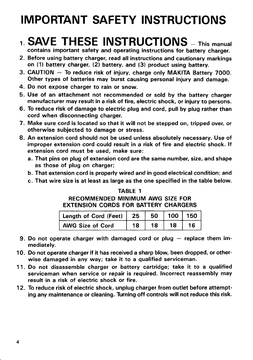
Length of Cord (Feet)
AWG Size of Cord
9.
Do not operate charger with damaged cord or plug - replace them im-
mediately.
IO.
Do
not operate charger if
wise damaged in any way; take
11.
Do not disassemble charger or battery cartridge; take
serviceman when service or repair is required. Incorrect reassembly may
result in a risk of electric shock or fire.
12.
To
reduce risk of electric shock, unplug charger from outlet before attempt-
ing any maintenance or cleaning. Turning off controls will not reduce this risk.
4
it
has received a sharp blow, been dropped, or other-
25
18
it
to a qualified serviceman.
100 150
50
18 18 16
it
to a qualified
Page 5

ADDITIONAL SAFETY RULES
FOR CHARGER
1.
Do not charge Battery Cartridge when temperature is
or ABOVE 4OoC
2.
Do not attempt to use a step-up transformer, an engine generator or DC power
receptacle.
3.
Do not allow anything to cover or clog the charger vents.
4.
Always cover the battery terminals
cartridge
5.
A
battery short can cause a large current flow, overheating, possible burns
and even a breakdown.
(1)
(2)
(3)
6.
Do not store the tool and Battery Cartridge in locations where the temperature may reach or exceed 5OoC (122OF).
7.
Do not incinerate the Battery Cartridge even
completely worn out. The battery cartridge can explode
is
Do not touch the terminals with any conductive material.
Avoid storing battery cartridge
as nails, coins, etc.
Do not expose battery cartridge to water or rain.
(104OF).
not used.
&
BATTERY CARTRIDGE
BELOW
with
the battery cover when the battery
in
a
container with other metal objects such
if
it
is severely damaged or is
in
10°C
a fire.
ADDITIONAL SAFETY RULES
(5OOF)
1.
Be aware that this
not have to be plugged into an electrical outlet.
2.
Don't use or leave the tool
3.
Don't use in rain.
4.
Check the socket carefully for cracks or damage before operation.
5.
To prevent bolts or nuts from being damaged,
tool
is always
in
damp or wet locations.
in
an operating condition, because
do
not overtighten them.
SAVE THESE INSTRUCTIONS.
it
does
5
Page 6

Installing or removing battery cartridge
.Always switch off the tool before insertion or removal of the battery cartridge.
.To remove the battery cartridge, pull out
the
set
plate on the tool andgrasp both
sides of the cartridge while withdrawing
from the barrel.
0
Do
not use force when inserting the battery cartridge.
If the cartridge does not slide in easily,
Charging
Plug the fast charger into your power
source. insert the battery cartridge
the plus and minus terminals on the battery cartridge are on the same sides
respective markings on the fast charger.
Insert the cartridge fully into the port
that
it
rests on the charger port floor.
The charging light will come on and charg-
ing will begin. If the charging light does
not come on, press the reset button. If the
charging light goes out within 10 seconds
even after pressing the reset button
couple of times, the battery cartridge
after the charging light goes out to press the reset button again.) Replace
one. When the charging light goes out after about one hour, you may remove the fully
charged battery cartridge.
After charging, unplug the charger from the power source.
so
as
I
it
I
it
is
not being inserted correctly.
that
their
so
a
is
dead. (CAUTION:
I------
I,
Wait
for more than 5 seconds
Battery cartridge
it
Set plate
with a new
I
I
CAUTION
0
Your new battery cartridge
0
If you try to charge a cartridge from a just-operated tool, sometimes the charging light
will not come on. If this occurs,
and try to charge
When you charge a new battery cartridge or a battery cartridge which has not been used
for
not indicate
it
0
If you wish to charge
fast charger.
6
:
is
not charged. You will need to charge
let
it
once more.
a
long period,
almost completely a couple of times.
it
may not accept a full charge. This
a
problem. You can recharge the battery cartridge fully after discharging
two
battery cartridges, allow 15 minutes between chargings on the
it
before use.
the cartridge cool off for a while. Then re-insert
is a normal condition and does
it
Page 7

Installing socket adapter
When you wish to use a smaller
install the socket adapter.
To
install
it,
insert the socket adapter into
the socket in the tool, making sure that the
tightening direction matches the arrow on
the tool.
To loosen the nut or bolt, turn the tool
over
(upside-down) and insert the socket
adapter into the socket in the tool.
Switch action
To start the tool, simply depress the switch
lever.
Release
the switch lever to stop.
size
socket,
Socket
I
adapter
I
CAUTION:
Before inserting the battery cartridge into the tool, always check to
Jever actuates properly and returns to the
"OFF"
position when released.
Switch
lever
see
that the switch
Operation
1.
Motor-driven semi-tightening operation
Make sure that the tightening direction
matches the arrow on the tool. Hold
the tool bv the orir, area and
socket over the nut or bolt. Turn the
tool on and continue to tighten until
the torque limiter actuates, then
the tool
CAUTION
When operating the tool, be sure to place the socket over the nut or bolt securely.
off
-.
:
dace
the
turn
3
'
Page 8

2.
Final manual tightening operation
After turning the tool off, perform the
final manual tightening operation by
pulling on the tool grip in the same
tightening direction.
The maximum
that can
1/2"
(socket
size
of
standard bolts
be
tightened with this tool
size:
13/16').
Refer to the
table for the correct tightening torque
and check the torque with
a
wrench.
torque
is
Standard
bolt
Size
M8
M10
M12
5/16"
3/8"
711 6"
112"
Tightening Socket
torque size
11 5 kg
.
cm
(8.3 ft
. Ibs.)
230 kg . cm
(16.6 ft. Ibs.)
400 kg . cm
(28.9 ft
.
Ibs.)
115kg.cm
.
Ibs.)
(8.3 ft
185 kg
.
cm
.
Ibs.)
296 kg . cm
.
Ibs.) 3/4"
.
.
Ibs.)
cm
439 kg
I
(13.4 ft
121.4 ft
(31.7 ft
I
13 mm
l7
mm
l9
mm
9/16"
21132"
13/16"
CAUTION
:
*When performing the final manual tightening operation, be sure to hold the grip area of
the tool.
as
*Avoid the following abusive techniques. They can cause the nut or bolt to break
as
cause tool damage.
I)
Gripping toward the end of the tool.
11)
Stepping on the tool.
Ill)
Strongly applying your weight to the tool.
IV)
Attaching a pipe or bar to the end of the tool to create more force on the tool.
0
During final tightening, if your hand does not feel an increasing force on the nut or bolt
as
you pull, the nut or bolt may already be tightened excessively. The nut or bolt may
be very close to breaking. Replace the nut or bolt with
3.
Loosening operation
To
loosen the nut or bolt, turn the tool over (upside-down). Loosen the nut or bolt by
a
new one.
well
pulling on the tool grip manually in the loosening direction. Then turn the tool on to
quickly and efficiently remove the nut or bolt.
8
Page 9

MAINTENANCE
CAUTION
Always be sure that the tool
attempting to perform inspection or maintenance.
To
should be performed
Makita replacement parts.
:
is
switched
maintain product SAFETY and RELlABl LITY, repairs, maintenance
by
Makita Authorized or Factory Service Centers, always using
off
and
the
battery cartridge
is
removed before
or
adjustment
9
Page 10

ACCESS0 R I
CAUTION
These accessories or attachments are recommended for use with your Makita tool specified in this
manual. The use of any other accessories or attachments might present
The accessories or attachments should be used only in the proper and intended manner.
e
Fast charger
Model DC7100
ES
:
a
risk
of
injury to persons.
e
Battery cartridge
Part
No.
632002-4
7000
*Charger 12V for car
Model DC7112
e
Socket adapter
(Square drive
Part
No.
9.5
size
785404-4
3/8")
Battery cover
Part
No.
414938-7
e
Socket adapter
(Square drive size 1 /2")
Part
No.
e
Battery holster
Holster
Part
No.
12.7
785403-6
holds
extra battery.
823033-36
10
Page 11

June-26-'86
CORDLESS RATCHET WRENCH
Model
69120
EN
Note: The switch and other part configurations
may differ from country to country.
11
Page 12

/LM
MODEL 6912D
$tD
DESCRIPTION
‘i,‘dn
A:D
DESCRIPTION
June-
26-’86
EN
~
1
2
Hex
Socket Head Bolt M4x18
2 1
3
4 1
5
6
7
8
9
10
11 1 Motor
12
13 1 Flat Washer 15
14 1 Internal
15
16
11
18 1
19 1
20 1
Sub Housing
2 Hex
Name
2
2
Flat
1
Housing
1
set
1 Switch
1 Compresrlon
1
3
3
1
R
Socket
Head
Boll
Spring
17
49
16
5
10
M4x25 (With Warherl
6
LIMITED
Plate
Hex Socker Head Bolt M4x25 (With Warherl
Washer 4
R
Plate
Lever
SpurGear
Gear
Sp~Gear
Pin3
Clutch Cam
Splndle
Steel
Ball
3
Flat
Washer
MAKflA
Warranty
Every Makita tool is thoroughly inspected and tested before leaving the factory.
be free of defects from workmanship and materials for the period of ONE YEAR from the date
origjnal purchase. Should any trouble develop during this one-year period, return the COMPLETE
tool, freight prepaid,
the trouble is caused by defective workmanship or material, Makita
replace) without charge.
This Warranty does not apply where:
repairs have been made or attempted by others:
repairs are required because of normal wear and tear:
The tool has been abused, misused
alterations have been made to the tool.
IN
NO EVENT SHALL MAKITA BE LIABLE FOR ANY INDIRECT, INCIDENTAL
SEOUENTIAL DAMAGES
APFLIES BOTH
MAKITA DISCLAIMS LIABILITY
WARRANTIES OF “MERCHANTABILITY” AND “FITNESS FOR A SPECIFIC PURPOSE.’’
AFTER THE ONE-YEAR TERM OF THIS WARRANTY.
This Warranty gives you specific legal rights, and you may also have other rights which vary from
state to state. Some states do not allow the exclusion or limitation of incidental or consequential
damages,
so
limitation on how long an implied warranty lasts,
to
one of Makita’s Factory or Authorized Service Centers. If inspection shows
or
improperly maintained;
FROM
DURING AND
THE SALE
AFTER
FOR
the above limitation or exclusion may not apply
7
21 1
22
23
24 1
25
26
21 1
28 1
29
30
31 1
32
33
34
35 1
36
31
38
39
40
ONE
YEAR WARRANTY
Policy
OR
THE
USE OF THE PRODUCT. THIS DISCLAIMER
TERM
OF
ANY IMPLIED WARRANTIES, INCLUDING IMPLIED
so
the above limitation may not apply
Needle Bearing 1015
1
Battery
Holder
Collar
1
Switch
Torsion
Spring
1
Spwg
1
Torslo”
Sleeve
Ratchet
1
1
Socker
1
Ring
1
1
1
4
1
2
2
THIS
WARRANTY.
to
Ratchet
Prn
Compresslo”
Steel
noustng
Hex
Sub Housing
Hex
Spring
5
Pawl
Spring
I
4
Pawl
Holder
21
Spring
18
4
SQrlng
Elall
3 5
L
Nut
M4
L
Nut
M4
Warher 4
will
repair (or at our option,
you. Some states do not allow
2
4
It
is warranted
-
OR
to
you.
to
of
CON-
Makita Corporation
3-11
-8,
Sumiyoshi-cho,
Anjo, Aichi
446
Japan
883549D065
PRINTED IN JAPAN
1992
-
5 - N
 Loading...