

Page 1
INSTRUCTION MANUAL
MANUEL D'INSTRUCTION
MANUAL DE INSTRUCCIONES
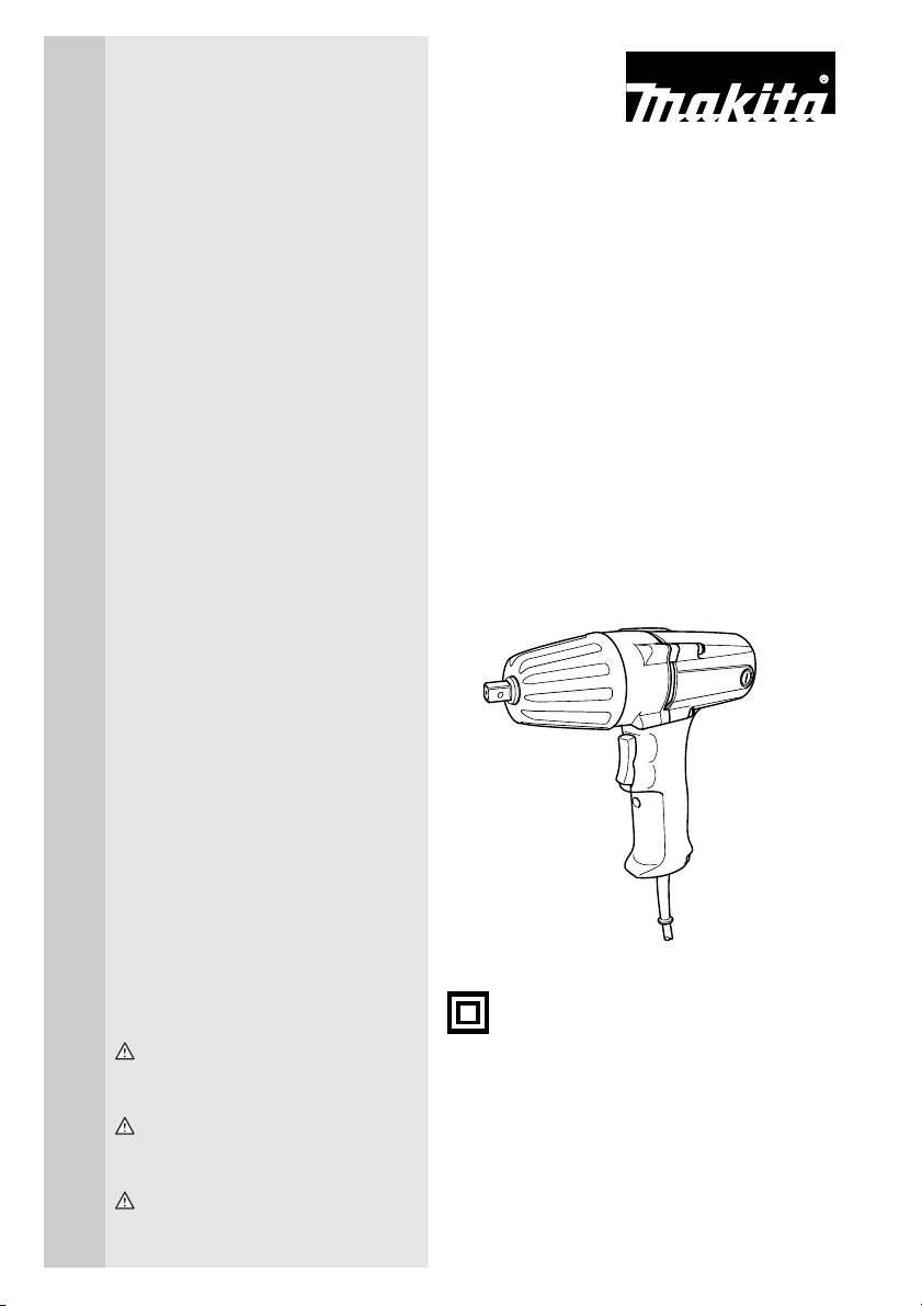
Impact Wrench
Boulonneuse à chocs
Llave de impacto
6905B
6906
002288
DOUBLE INSULATION
DOUBLE ISOLATION
DOBLE AISLAMIENTO
WARNING:
For your personal safety, READ and UNDERSTAND before using.
SAVE THESE INSTRUCTIONS FOR FUTURE REFERENCE.
AVERTISSEMENT:
Pour votre propre sécurité, prière de lire attentivement avant l’utilisation.
GARDER CES INSTRUCTIONS POUR RÉFÉRENCE ULTÉRIEURE.
ADVERTENCIA:
Para su seguridad personal, LEA DETENIDAMENTE este manual antes de usar la herramienta.
GUARDE ESTAS INSTRUCCIONES PARA FUTURA REFERENCIA.
Page 2

ENGLISH
SPECIFICATIONS
Model 6905B 6906
Capacities Bolt size M12 - M20 (1/2” - 3/4”) M16 - M22 (5/8” - 7/8”)
Square drive 12.7 mm (1/2”) 19 mm (3/4”)
No load speed (RPM) 1,700/min. 1,700/min.
Impacts per minute 2,000 1,600
Max. fastening torque 294 N.m (217 ft.lbs) 588 N.m (433 ft.lbs)
Overall length 270 mm (10-1/4”) 327 mm (12-7/8”)
Net weight 2.7 kg (6 lbs) 5 kg (11 lbs)
• Due to our continuing programme of research and development, the specifications herein are subject to change
without notice.
• Note: Specifications may differ from country to country.
GENERAL SAFETY RULES
GEA001-3
WARNING:
Read all instructions. Failure to follow all
instructions listed below may result in
electric shock, fire and/or serious injury. The
term “power tool” in all of the warnings listed
below refers to your mains-operated
(corded) power tool or battery-operated
(cordless) power tool.
SAVE THESE INSTRUCTIONS
Work area safety
1. Keep work area clean and well lit. Cluttered and
dark areas invite accidents.
2. Do not operate power tools in explosive
atmospheres, such as in the presence of
flammable liquids, gases or dust. Power tools
create sparks which may ignite the dust or fumes.
3. Keep children and bystanders away while
operating a power tool. Distractions can cause you
to lose control.
Electrical safety
4. Power tool plugs must match the outlet. Never
modify the plug in any way. Do not use any
adapter plugs with earthed (grounded) power
tools. Unmodified plugs and matching outlets will
reduce risk of electric shock.
5. Avoid body contact with earthed or grounded
surfaces such as pipes, radiators, ranges and
refrigerators. There is an increased risk of electric
shock if your body is earthed or grounded.
6. Do not expose power tools to rain or wet
conditions. Water entering a power tool will
increase the risk of electric shock.
7. Do not abuse the cord. Never use the cord for
carrying, pulling or unplugging the power tool.
Keep cord away from heat, oil, sharp edges or
moving parts. Damaged or entangled cords
increase the risk of electric shock.
8. When operating a power tool outdoors, use an
extension cord suitable for outdoor use. Use of a
cord suitable for outdoor use reduces the risk of
electric shock.
Personal safety
9. Stay alert, watch what you are doing and use
common sense when operating a power tool. Do
not use a power tool while you are tired or under
the influence of drugs, alcohol or medication. A
moment of inattention while operating power tools
may result in serious personal injury.
10. Use safety equipment. Always wear eye
protection. Safety equipment such as dust mask,
non-skid safety shoes, hard hat, or hearing
protection used for appropriate conditions will
reduce personal injuries.
11. Avoid accidental starting. Ensure the switch is in
the off-position before plugging in. Carrying
power tools with your finger on the switch or
plugging in power tools that have the switch on
invites accidents.
12. Remove any adjusting key or wrench before
turning the power tool on. A wrench or a key left
attached to a rotating part of the power tool may
result in personal injury.
13. Do not overreach. Keep proper footing and
balance at all times. This enables better control of
the power tool in unexpected situations.
2
Page 3

14. Dress properly. Do not wear loose clothing or
jewellery. Keep your hair, clothing, and gloves
away from moving parts. Loose clothes, jewellery
or long hair can be caught in moving parts.
15. If devices are provided for the connection of
dust extraction and collection facilities, ensure
these are connected and properly used. Use of
these devices can reduce dust-related hazards.
Power tool use and care
16. Do not force the power tool. Use the correct
power tool for your application. The correct power
tool will do the job better and safer at the rate for
which it was designed.
17. Do not use the power tool if the switch does not
turn it on and off. Any power tool that cannot be
controlled with the switch is dangerous and must be
repaired.
18. Disconnect the plug from the power source and/
or the battery pack from the power tool before
making any adjustments, changing accessories,
or storing power tools. Such preventive safety
measures reduce the risk of starting the power tool
accidentally.
19. Store idle power tools out of the reach of
children and do not allow persons unfamiliar
with the power tool or these instructions to
operate the power tool. Power tools are dangerous
in the hands of untrained users.
20. Maintain power tools. Check for misalignment or
binding of moving parts, breakage of parts and
any other condition that may affect the power
tools operation. If damaged, have the power tool
repaired before use. Many accidents are caused by
poorly maintained power tools.
21. Keep cutting tools sharp and clean. Properly
maintained cutting tools with sharp cutting edges
are less likely to bind and are easier to control.
22. Use the power tool, accessories and tool bits
etc. in accordance with these instructions and in
the manner intended for the particular type of
power tool, taking into account the working
conditions and the work to be performed. Use of
the power tool for operations different from those
intended could result in a hazardous situation.
Service
23. Have your power tool serviced by a qualified
repair person using only identical replacement
parts. This will ensure that the safety of the power
tool is maintained.
24. Follow instruction for lubricating and changing
accessories.
25. Keep handles dry, clean and free from oil and
grease.
SPECIFIC SAFETY RULES
GEB009-2
DO NOT let comfort or familiarity with
product (gained from repeated use)
replace strict adherence to recipro saw
safety rules. If you use this tool unsafely
or incorrectly, you can suffer serious
personal injury.
1. Hold power tools by insulated gripping surfaces
when performing an operation where the cutting
tool may contact hidden wiring or its own cord.
Contact with a “live” wire will make exposed metal
parts of the tool “live” and shock the operator.
2. Wear ear protectors.
3. Check the socket carefully for wear, cracks or
damage before installation.
4. Hold the tool firmly.
5. Always be sure you have a firm footing.
Be sure no one is below when using the tool in
high locations.
6. The proper fastening torque may differ
depending upon the kind or size of the bolt.
Check the torque with a torque wrench.
SAVE THESE INSTRUCTIONS
WARNING:
MISUSE or failure to follow the safety
rules stated in this instruction manual
may cause serious personal injury.
SYMBOLS
USD202-2
The followings show the symbols used for tool.
V ...........................volts
A........................... amperes
Hz .........................hertz
.................. alternating current
.......................no load speed
.......................Class II Construction
.../min ...................revolutions or reciprocation per
.................. number of blow
minute
3
Page 4
FUNCTIONAL DESCRIPTION
CAUTION:
• Always be sure that the tool is switched off and
unplugged before adjusting or checking function on
the tool.
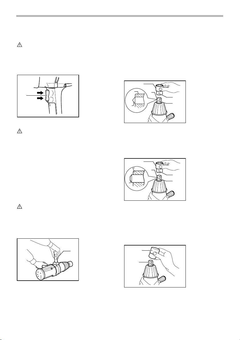
Switch action
1
002312
1. Switch trigger
Selecting correct socket
Always use the correct size socket for bolts and nuts. An
incorrect size socket will result in inaccurate and
inconsistent fastening torque and/or damage to the bolt
or nut.
Installing or removing socket
For model 6905B
For tool with light fit detent pin
1
2
4
2
007321
3
4
1. Socket
2. Anvil
3. Hole
4. Detent pin
CAUTION:
• Before plugging in the tool, always check to see
that the switch trigger actuates properly and returns
to the “OFF” position when released.
• Change the direction of rotation only when the tool
comes to a complete stop. Changing it before the
tool stops may damage the tool.
The switch is reversible, providing either clockwise or
counterclockwise rotation. To start the tool, simply pull
the lower part of the switch trigger for clockwise or the
upper part for counterclockwise. Release the switch
trigger to stop.
ASSEMBLY
CAUTION:
• Always be sure that the tool is switched off and
unplugged before carrying out any work on the tool.
Installing side grip
For 6906 only
Fit the side grip into the groove on the middle of the
hammer case and fasten securely.
002332
1. Side grip
1
Align the hole in the side of the socket with the detent pin
on the anvil and push it onto the anvil of the tool until it
locks into place. Tap it lightly if required.
To remove the socket, simply pull it off.
For tool with firm fit detent pin
1
2
2
4
To install the socket, align the hole in the side of the
socket with the detent pin on the anvil.
Push the socket onto the anvil until it snaps into place.
Tap it lightly if required.
To remove the socket, depress the detent pin through the
hole in the socket and pull the socket off the anvil.
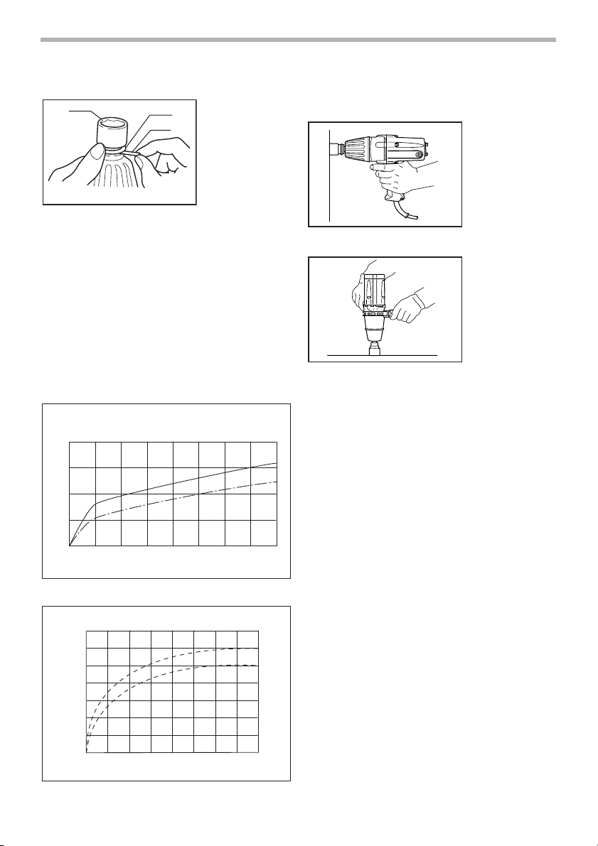
For model 6906
1
2
To install the socket, push it onto the anvil of the tool until
it locks into place.
To remove the socket, simply pull it off.
007322
3
4
002338
1. Socket
2. Anvil
3. Hole
4. Detent pin
1. Socket
2. Anvil
4
Page 5
For socket with O-ring and pin
1
005300
2
3
1. Socket
2. O-ring
3. Pin
Move the O-ring out of the groove in the socket and
remove the pin from the socket. Fit the socket onto the
anvil of the tool so that the hole in the socket is aligned
with the hole in the anvil. Insert the pin through the hole
in the socket and anvil. Then return the O-ring to the
original position in the socket groove to retain the pin. To
remove the socket, follow the installation procedures in
reverse.
OPERATION
The proper fastening torque may differ depending upon
the kind or size of the bolt, the material of the workpiece
to be fastened, etc. The relation between fastening
torque and fastening time is shown in the figures.
(ft.lbs)
N.m
400
(258)
300
(216)
200
(144)
Fastening torque
100
(72)
12345678
0
(ft.lbs)
N.m
700
(505)
600
(433)
500
(361)
400
(288)
300
(216)
Fastening torque
200
(144)
100
(72)
0123456
Fastening time
Fastening time
For 6905B
90% of rated voltage
Rated voltage
90% of rated voltage
002348
Rated voltage
002351
For 6906
78
(S)
(S)
Hold the tool firmly and place the socket over the bolt or
nut. Turn the tool on and fasten for the proper fastening
time.
007443
6905B
007445
6906
NOTE:
• Hold the tool pointed straight at the bolt or nut.
• Excessive fastening torque may damage the bolt/
nut or socket. Before starting your job, always
perform a test operation to determine the proper
fastening time for your bolt or nut.
The fastening torque is affected by a wide variety of
factors including the following. After fastening, always
check the torque with a torque wrench.
1. Vol ta ge
Voltage drop will cause a reduction in the fastening
torque.
2. Socket
• Failure to use the correct size socket will cause
a reduction in the fastening torque.
• A worn socket (wear on the hex end or square
end) will cause a reduction in the fastening
torque.
3. Bolt
• Even though the torque coefficient and the
class of bolt are the same, the proper fastening
torque will differ according to the diameter of
bolt.
• Even though the diameters of bolts are the
same, the proper fastening torque will differ
according to the torque coefficient, the class of
bolt and the bolt length.
4. The use of the universal joint or the extension bar
somewhat reduces the fastening force of the impact
wrench. Compensate by fastening for a longer
period of time.
5
Page 6
5. The manner of holding the tool or the material of
driving position to be fastened will affect the torque.
MAINTENANCE
CAUTION:
• Always be sure that the tool is switched off and
unplugged before attempting to perform inspection
or maintenance.
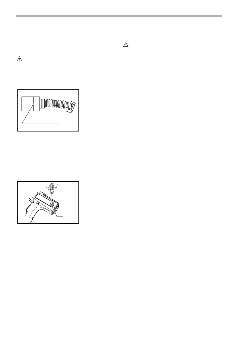
Replacing carbon brushes
Remove and check the carbon brushes regularly.
Replace when they wear down to the limit mark. Keep
the carbon brushes clean and free to slip in the holders.
Both carbon brushes should be replaced at the same
time. Use only identical carbon brushes.
Use a screwdriver to remove the brush holder caps. Take
out the worn carbon brushes, insert the new ones and
secure the brush holder caps.
To maintain product SAFETY and RELIABILITY, repairs,
any other maintenance or adjustment should be
performed by Makita Authorized or Factory Service
Centers, always using Makita replacement parts.
001145
1. Limit mark
1
002372
1. Screwdriver
2. Brush holder
1
2
cap
ACCESSORIES
CAUTION:
• These accessories or attachments are
recommended for use with your Makita tool
specified in this manual. The use of any other
accessories or attachments might present a risk of
injury to persons. Only use accessory or
attachment for its stated purpose.
If you need any assistance for more details regarding
these accessories, ask your local Makita Service Center.
• Sockets
• Extension bar
• Universal joint
MAKITA LIMITED ONE YEAR WARRANTY
Warranty Policy
Every Makita tool is thoroughly inspected and tested
before leaving the factory. It is warranted to be free of
defects from workmanship and materials for the period of
ONE YEAR from the date of original purchase. Should
any trouble develop during this one year period, return
the COMPLETE tool, freight prepaid, to one of Makita’s
Factory or Authorized Service Centers. If inspection
shows the trouble is caused by defective workmanship or
material, Makita will repair (or at our option, replace)
without charge.
This Warranty does not apply where:
• repairs have been made or attempted by others:
• repairs are required because of normal wear and
tear:
• the tool has been abused, misused or improperly
maintained:
• alterations have been made to the tool.
IN NO EVENT SHALL MAKITA BE LIABLE FOR ANY
INDIRECT, INCIDENTAL OR CONSEQUENTIAL
DAMAGES FROM THE SALE OR USE OF THE
PRODUCT. THIS DISCLAIMER APPLIES BOTH
DURING AND AFTER THE TERM OF THIS
WARRANTY.
MAKITA DISCLAIMS LIABILITY FOR ANY IMPLIED
WARRANTIES, INCLUDING IMPLIED WARRANTIES
OF “MERCHANTABILITY” AND “FITNESS FOR A
SPECIFIC PURPOSE,” AFTER THE ONE YEAR TERM
OF THIS WARRANTY.
This Warranty gives you specific legal rights, and you
may also have other rights which vary from state to state.
Some states do not allow the exclusion or limitation of
incidental or consequential damages, so the above
limitation or exclusion may not apply to you. Some states
do not allow limitation on how long an implied warranty
lasts, so the above limitation may not apply to you.
EN0006-1
6
Page 7

FRANÇAIS
SPÉCIFICATIONS
Modèle 6905B 6906
Capacités Taille de boulon M12 - M20 (1/2” - 3/4”) M16 - M22 (5/8” - 7/8”)
Tournevis carré 12.7 mm (1/2”) 19 mm (3/4”)
Vitesse à vide (T/MIN) 1,700/min. 1,700/min.
Percussions par minute 2,000 1,600
Couple de serrage max. 294 N.m (217 ft.lbs) 588 N.m (433 ft.lbs)
Longueur totale 270 mm (10-1/4”) 327 mm (12-7/8”)
Poids net 2.7 kg (6 lbs) 5 kg (11 lbs)
• Le fabricant se réserve le droit de modifier sans avertissement les spécifications.
• Note: Les spécifications peuvent varier selon les pays.
CONSIGNES DE SÉCURITÉ
GÉNÉRALES
GEA001-3
AVERTISSEMENT:
Veuillez lire l’ensemble des présentes
instructions. Il y a risque de choc
électrique, d’incendie et/ou de blessure
grave si toutes les instructions énumérées
ci-dessous ne sont pas respectées. Dans
tous les avertissements ci-dessous, le terme
“outil électrique” fait référence aux outils
électriques qui fonctionnent sur le secteur
(avec un cordon d’alimentation) et aux outils
électriques alimentés par batterie (sans
cordon d’alimentation).
CONSERVEZ CES
INSTRUCTIONS
Sécurité de la zone de travail
1. Maintenez la zone de travail propre et bien
éclairée. Les zones de travail encombrées et
sombres ouvrent grande la porte aux accidents.
2. N’utilisez pas les outils électriques dans des
atmosphères explosives, telles qu’en présence
de liquides, de gaz ou de poussières
inflammables. Les outils électriques produisent des
étincelles au contact desquelles la poussière ou les
vapeurs risqueraient de s’enflammer.
3. Assurez-vous qu’aucun enfant ou passant ne
s’approche pendant que vous utilisez un outil
électrique. Vous risquez de perdre la maîtrise de
l’outil si votre attention est détournée.
Sécurité en matière d’électricité
4. La fiche des outils électriques doit être conçue
pour la prise de courant utilisée. Ne modifiez
jamais la fiche de quelque façon que ce soit.
N’utilisez aucun adaptateur de fiche sur les
outils électriques avec mise à la terre. En ne
modifiant pas les fiches et en les insérant dans des
prises de courant pour lesquelles elles ont été
conçues vous réduirez les risques de choc
électrique.
5. Évitez tout contact corporel avec les surfaces
mises à la terre, telles que les tuyaux, radiateurs,
cuisinières et réfrigérateurs. Le risque de choc
électrique augmentera si votre corps se trouve mis à
la terre.
6. N’exposez pas les outils électriques à la pluie et
évitez qu’ils ne soient mouillés. Les risques de
choc électrique augmentent lorsque de l’eau
pénètre dans un outil électrique.
7. Ne maltraitez pas le cordon. N’utilisez jamais le
cordon pour transporter l’outil électrique, pour
tirer dessus ou pour le débrancher. Maintenez le
cordon à l’écart des sources de chaleur, de
l’huile, des objets à bords tranchants et des
pièces en mouvement. Le risque de choc
électrique augmente lorsque les cordons sont
endommagés ou enchevêtrés.
8. Lorsque vous utilisez un outil électrique à
l’extérieur, utilisez un cordon prolongateur prévu
à cette fin. Les risques de choc électrique
diminuent lorsqu’un cordon conçu pour l’extérieur
est utilisé.
Sécurité personnelle
9. Restez alerte, attentif à vos mouvements et
faites preuve de bon sens lorsque vous utilisez
7
Page 8

un outil électrique. Évitez d’utiliser un outil
électrique si vous êtes fatigué ou si vous avez
pris une drogue, de l’alcool ou un médicament.
Un moment d’inattention pendant l’utilisation d’un
outil électrique peut entraîner une grave blessure.
10. Utilisez des dispositifs de sécurité. Portez
toujours des lunettes de protection. Les risques
de blessure diminueront si vous utilisez des
dispositifs de sécurité tels qu’un masque
antipoussières, des chaussures à semelle
antidérapante, une coiffure résistante ou une
protection d’oreilles.
11. Prévenez tout démarrage accidentel. Assurezvous que l’interrupteur est en position d’arrêt
avant de brancher l’outil. Vous ouvrez toute
grande la porte aux accidents si vous transportez
les outils électriques en gardant le doigt sur la
gâchette ou si vous les branchez alors que
l’interrupteur se trouve en position de marche.
12. Retirez toute clé de réglage ou autre type de clé
avant de mettre l’outil sous tension. Toute clé
laissée en place sur une pièce rotative de l’outil
électrique peut entraîner une blessure.
13. Maintenez une position stable. Assurez-vous
d’avoir une bonne prise au sol et une bonne
position d’équilibre en tout temps. Vous a urez
ainsi une meilleure maîtrise de l’outil en cas de
situation imprévue.
14. Portez des vêtements adéquats. Ne portez ni
vêtements amples ni bijoux. Vous devez
maintenir cheveux, vêtements et gants à l’écart
des pièces en mouvement. Les pièces en
mouvement risqueraient de happer les vêtements
amples, les bijoux ou les cheveux longs.
15. Si des accessoires sont fournis pour raccorder
un appareil d’aspiration et de collecte de la
poussière, assurez-vous que les raccordements
sont corrects et que l’appareil est bien utilisé.
L’utilisation de tels accessoires permet de réduire
les risques liés à la présence de poussière dans l’air.
Utilisation et entretien des outils
électriques
16. Ne forcez pas l’outil électrique. Utilisez l’outil
électrique adéquat suivant le type de travail à
effectuer. Si vous utilisez l’outil électrique adéquat
et respectez le régime pour lequel il a été conçu, il
effectuera un travail de meilleure qualité et de façon
plus sécuritaire.
17. N’utilisez pas l’outil électrique s’il n’est pas
possible de mettre sa gâchette en position de
marche et d’arrêt. Un outil électrique dont
l’interrupteur est défectueux représente un danger et
doit être réparé.
18. Débranchez la fiche de la source d’alimentation
et/ou retirez le bloc-pile de l’outil électrique
avant d’effectuer tout réglage, de changer un
accessoire ou de ranger l’outil électrique. Ces
mesures préventives réduiront les risques de
démarrage accidentel de l’outil électrique.
19. Après l’utilisation d’un outil électrique, rangez-le
hors de portée des enfants et ne laissez aucune
personne l’utiliser si elle n’est pas familiarisée
avec l’outil électrique ou les présentes
instructions d’utilisation. Les outils électriques
représentent un danger entre les mains de
personnes qui n’en connaissent pas le mode
d’utilisation.
20. Ne négligez pas l’entretien des outils
électriques. Assurez-vous que les pièces
mobiles ne sont ni désalignées ni coincées,
qu’aucune pièce n’est cassée et que l’outil
électrique n’a subi aucun dommage pouvant
affecter son bon fonctionnement. Si l’outil
électrique est endommagé, faites-le réparer
avant de l’utiliser à nouveau. De nombreux
accidents sont causés par des outils électriques mal
entretenus.
21. Maintenez les outils tranchants bien aiguisés et
propres. Un outil tranchant dont l’entretien est
effectué correctement et dont les bords sont bien
aiguisés risquera moins de se coincer et sera plus
facile à maîtriser.
22. Utilisez l’outil électrique, ses accessoires, ses
embouts, etc., en respectant les présentes
instructions et de la façon prévue pour ce type
particulier d’outil électrique, en tenant compte
des conditions de travail et du type de travail à
effectuer. L’utilisation d’un outil électrique à des fins
autres que celles prévues est potentiellement
dangereuse.
Service
23. Faites réparer votre outil électrique par un
réparateur qualifié qui utilise des pièces de
rechange identiques aux pièces d’origine. Cela
permettra d’assurer le maintien de la sûreté de l’outil
électrique.
24. Suivez les instructions de lubrification et de
changement des accessoires.
25. Maintenez les poignées sèches, propres et
exemptes d’huile ou de graisse.
RÈGLES DE SÉCURITÉ
PARTICULIÈRES
GEB009-2
NE vous laissez PAS tromper (au fil d’une
utilisation répétée) par un sentiment
d’aisance et de familiarité avec le
produit, en négligeant le respect
rigoureux des consignes de sécurité qui
accompagnent la scie récipro. Si vous
n’utilisez pas cet outil de façon sûre et
8
Page 9

adéquate, vous courez un risque de
blessure grave.
1. Tenez l’outil électrique par ses surfaces de prise
isolées pendant toute opération où l’outil de
coupe pourrait venir en contact avec un câblage
dissimulé ou avec son propre cordon. En cas de
contact avec un conducteur sous tension, les pièces
métalliques à découvert de l’outil transmettraient un
choc électrique à l’utilisateur.
2. Portez une protection d’oreilles.
3. Avant installation, vérifiez soigneusement que la
douille ne porte ni marque d’usure, ni fissures
ou tout autre dommage.
4. Tenez l’outil fermement.
5. Adoptez toujours une position de travail vous
assurant d’un bon équilibre.
Assurez-vous qu’il n’y a personne plus bas
lorsque vous utilisez l’outil en position élevée.
6. Le couple de serrage correct peut varier selon le
type ou la taille du boulon. Vérifiez-le à l’aide
d’une clé dynamométrique.
CONSERVEZ CE MODE
D’EMPLOI
AVERTISSEMENT:
Une MAUVAISE UTILISATION de l’outil ou
l’ignorance des consignes de sécurité du
présent manuel d’instructions peuvent
entraîner une grave blessure.
SYMBOLES
USD202-2
Les symboles utilisés pour l’outil sont présentés cidessous.
V............................volts
A ...........................ampères
Hz..........................hertz
...................courant alternatif
.......................vitesse à vide
.......................construction, catégorie II
.../min....................tours ou alternances par minute
..................nombre de frappes
DESCRIPTION DU
FONCTIONNEMENT
ATTENTION:
• Assurez-vous toujours que l’outil est hors tension et
débranché avant de l’ajuster ou de vérifier son
fonctionnement.
Interrupteur
1
ATTENTION:
• Avant de brancher l’outil, assurez-vous toujours
que la gâchette fonctionne correctement et revient
en position d’arrêt une fois relâchée.
• Attendez que l’outil soit complètement arrêté avant
de changer le sens de rotation. Vous risquez
d’endommager l’outil si vous changez le sens de
rotation avant que l’outil ne soit complètement
arrêté.
L’interrupteur est réversible, permettant d’obtenir une
rotation dans le sens des aiguilles d’une montre ou en
sens inverse. Pour faire démarrer l’outil, appuyez
simplement sur la partie inférieure de la gâchette pour
une rotation dans le sens des aiguilles d’une montre, ou
sur sa partie supérieure pour une rotation en sens
inverse. Pour l’arrêter, relâchez la gâchette.
002312
1. Gâchette
ASSEMBLAGE
ATTENTION:
• Avant d’effectuer toute intervention sur l’outil,
assurez-vous toujours qu’il est hors tension et
débranché.
Installation de la poignée latérale
Pour 6906 uniquement
002332
1. Poignée latérale
1
9
Page 10

Alignez la poignée latérale sur l’entaille qui se trouve au
milieu du carter du mécanisme de frappe, puis serrez
fermement.
Sélection de la douille
Pour certains modèles il existe différents types de
douilles ou embouts, suivant le travail à effectuer.
Veuillez choisir et installer une douille ou un embout qui
convient au travail à effectuer.
Installation et retrait de la douille
Pour le modèle 6905B
Pour outil avec cheville d’arrêt à ajustement léger
1
2
2
4
007321
3
4
1. Douille
2. Enclume
3. Orifice
4. Broche de
détente
Pour installer la douille, enfoncez-la sur le piton de l’outil
jusqu’à ce qu’elle se verrouille en position.Pour retirer la
douille, tirez simplement dessus.
Pour douille avec joint torique et tige
1
005300
2
3
1. Douille
2. Joint torique
3. Broche
Retirez le joint torique de la rainure de la douille et retirez
la tige de la douille. Insérez la douille dans le piton de
l’outil de façon que l’orifice de la douille soit aligné sur
l’orifice du piton. Insérez la tige dans l’orifice de la douille
et dans celui du piton. Puis, ramenez le joint torique à sa
position d’origine dans la rainure de la douille pour verrouiller la tige. Pour retirer la douille, procédez dans
l’ordre inverse de l’installation.
Alignez l’orifice qui se trouve du côté de la douille sur la
cheville d’arrêt du piton et appuyez-la contre le piton de
l’outil jusqu’à ce qu’elle se mette en place en émettant un
bruit sec. Si nécessaire, frappez légèrement dessus.
Pour retirer la douille, tirez simplement dessus.
Pour outil avec cheville d'arrêt à ajustement ferme
1
2
2
4
007322
3
4
1. Douille
2. Enclume
3. Orifice
4. Broche de
détente
Pour installer la douille, enfoncez-la sur le piton de l’outil
jusqu’à ce qu’elle se verrouille en position.
Pour retirer la douille, tirez simplement dessus.
Pour le modèle 6906
1
002338
1. Douille
2. Enclume
2
UTILISATION
Le couple de serrage adéquat peut varier suivant la sorte
ou taille de boulon, suivant le matériau dont se compose
la pièce faisant l’objet du serrage, etc. La relation entre le
couple de serrage et le temps de serrage est indiquée
dans les figures.
(ft.lbs)
N.m
400
(258)
300
(216)
200
(144)
Couple de serrage
100
(72)
12345678
0
Pour 6905B
90% de tension nominale
Temps de serrage
002348
Tension nominale
(S)
10
Page 11

002351
(ft.lbs)
N.m
700
(505)
600
(433)
500
(361)
400
(288)
300
(216)
Couple de serrage
200
(144)
100
(72)
0123456
Temps de serrage
Pour 6906
Tension nominale
90% de tension nominale
78
(S)
Saisissez fermement l’outil et placez la douille sur le
boulon ou l’écrou. Mettez l’outil en marche et procédez
au serrage, en appliquant le temps de serrage adéquat.
007443
6905B
007445
6906
2. Douille
• L’utilisation d’une douille de mauvaise
dimension entraînera une réduction du couple
de serrage.
• Une douille usée (usure sur l’extrémité
hexagonale ou l’extrémité carrée) entraînera
une réduction du couple de serrage.
3. Boulon
• Même si le coefficient du couple et la catégorie
du boulon sont les mêmes, le couple de
serrage variera en fonction du diamètre de
boulon.
• Même si les diamètres des boulons sont les
mêmes, le couple de serrage variera en
fonction du coefficient de couple, de la
catégorie du boulon et de la longueur du
boulon.
4. L’utilisation d’un joint universel ou d’une barre de
rallonge réduit quelque peu la force de serrage de
la boulonneuse. Compenser en serrant plus
longtemps.
5. Le couple de serrage est affecté par la façon dont
vous tenez l’outil ou la pièce, ou par la position de
vissage.
ENTRETIEN
ATTENTION:
• Assurez-vous toujours que l’outil est hors tension et
débranché avant d’y effectuer tout travail
d’inspection ou d’entretien.
Remplacement des charbons
001145
1. Trait de limite
d’usure
NOTE:
• Tenez votre outil bien droit sur le boulon ou l’écrou.
• Un couple de serrage excessif risque
d’endommager le boulon/l’écrou ou la douille. Avant
de commencer le travail, effectuez toujours un
essai pour vérifier que le temps de serrage
conviennent pour le boulon ou l’écrou en question.
Le couple de serrage dépend d’un certain nombre de
facteurs, comme suit. Une fois le serrage terminé,
vérifiez toujours le couple avec une clé dynamométrique.
1. Te ns i o n
Une baisse de tension entraînera une réduction du
couple de serrage.
1
Retirez et vérifiez régulièrement les charbons.
Remplacez-les lorsqu’ils sont usés jusqu’au trait de limite
d’usure. Maintenez les charbons propres et en état de
glisser aisément dans les porte-charbon. Les deux
charbons doivent être remplacés en même temps.
N’utilisez que des charbons identiques.
Utilisez un tournevis pour retirer les bouchons de portecharbon. Enlevez les charbons usés, insérez-en de
nouveaux et revissez solidement les bouchons de portecharbon.
11
Page 12

002372
1. Tournevis
2. Bouchon de
1
2
Pour maintenir la SÉCURITÉ et la FIABILITÉ du produit,
les réparations, tout autre travail d’entretien ou de
réglage doivent être effectués dans un centre de service
Makita agréé ou un centre de service de l’usine Makita,
exclusivement avec des pièces de rechange Makita.
porte-charbon
ACCESSOIRES
ATTENTION:
• Ces accessoires ou pièces complémentaires sont
recommandés pour l’utilisation avec l’outil Makita
spécifié dans ce mode d’emploi. L’utilisation de tout
autre accessoire ou pièce complémentaire peut
comporter un risque de blessure. N’utilisez les
accessoires ou pièces qu’aux fins auxquelles ils ont
été conçus.
Si vous désirez obtenir plus de détails concernant ces
accessoires, veuillez contacter le centre de service
après-vente Makita le plus près.
• Douilles
• Barre de rallonge
• Joint universel
GARANTIE LIMITÉE D’UN AN MAKITA
Politique de garantie
Chaque outil Makita est inspecté rigoureusement et testé
avant sa sortie d’usine. Nous garantissons qu’il sera
exempt de défaut de fabrication et de vice de matériau
pour une période d’UN AN à partir de la date de son
achat initial. Si un problème quelconque devait survenir
au cours de cette période d’un an, veuillez retourner
l’outil COMPLET, port payé, à une usine ou à un centre
de service après-vente Makita. Makita réparera l’outil
gratuitement (ou le remplacera, à sa discrétion) si un
défaut de fabrication ou un vice de matériau est
découvert lors de l’inspection.
Cette garantie ne s’applique pas dans les cas où:
• des réparations ont été effectuées ou tentées par
un tiers:
• des réparations s’imposent suite à une usure
normale:
• l’outil a été malmené, mal utilisé ou mal entretenu:
• l’outil a subi des modifications.
MAKITA DÉCLINE TOUTE RESPONSABILITÉ POUR
TOUT DOMMAGE ACCESSOIRE OU INDIRECT LIÉ À
EN0006-1
LA VENTE OU À L’UTILISATION DU PRODUIT. CET
AVIS DE NON-RESPONSABILITÉ S’APPLIQUE À LA
FOIS PENDANT ET APRÈS LA PÉRIODE COUVERTE
PAR CETTE GARANTIE.
MAKITA DÉCLINE TOUTE RESPONSABILITÉ QUANT
À TOUTE GARANTIE TACITE, INCLUANT LES
GARANTIES TACITES DE “QUALITÉ MARCHANDE” ET
“ADÉQUATION À UN USAGE PARTICULIER” APRÈS
LA PÉRIODE D’UN AN COUVERTE PAR CETTE
GARANTIE.
Cette garantie vous donne des droits spécifiques
reconnus par la loi, et possiblement d’autres droits, qui
varient d’un État à l’autre. Certains États ne permettant
pas l’exclusion ou la limitation des dommages
accessoires ou indirects, il se peut que la limitation ou
exclusion ci-dessus ne s’applique pas à vous. Certains
États ne permettant pas la limitation de la durée
d’application d’une garantie tacite, il se peut que la
limitation ci-dessus ne s’applique pas à vous.
12
Page 13

ESPAÑOL
ESPECIFICACIONES
Modelo 6905B 6906
Especificaciones eléctricas en México
Capacidades Tamaño del perno M12 - M20 (1/2” - 3/4”) M16 - M22 (5/8” - 7/8”)
Adaptador cuadrado 12,7 mm (1/2”) 19 mm (3/4”)
Revoluciones por minuto (r.p.m.) 1 700/min. 1 700/min.
Impactos por minuto 2 000 1 600
To rs i ón de fijación máxima 294 N.m (217 ft.lbs) 588 N.m (433 ft.lbs)
Longitud total 270 mm (10-1/4”) 327 mm (12-7/8”)
Peso neto 2,7 kg (6 lbs) 5 kg (11 lbs)
• Debido a un programa continuo de investigación y desarrollo, las especificaciones aquí dadas están sujetas a
cambios sin previo aviso.
• Nota: Las especificaciones pueden ser diferentes de país a país.
115 V 4 A 50/60 Hz 115 V 9 A 50/60 Hz
NORMAS GENERALES DE
SEGURIDAD
GEA001-3
AVISO:
Lea todas las instrucciones. Si no cumple
con las instrucciones aquí detalladas, se
puede producir una descarga eléctrica,
incendio y/o heridas de gravedad. El
término “herramienta eléctrica” en todas las
advertencias que figuran a continuación se
refiere a la herramienta eléctrica alimentada
por la red principal (con cable) o a la
operada por batería (sin cable).
GUARDE ESTAS
INSTRUCCIONES
Seguridad del área de trabajo
1. Mantenga el área de trabajo limpia y bien
iluminada. Las áreas oscuras y desordenadas son
propensas a accidentes.
2. No opere herramientas eléctricas en atmósferas
explosivas tales como en presencia de polvo,
gases o líquidos inflamables. Las herramientas
eléctricas producen chispas que puede encender el
polvo o los gases.
3. Mantenga a los niños y personas cercanas
alejadas mientras opera la herramienta eléctrica.
Si se distrae, puede perder el control de la
herramienta.
Seguridad eléctrica
4. El enchufe de la herramienta eléctrica debe
coincidir con la ficha. Nunca modifique el
enchufe. No use ningún adaptador con las
herramientas eléctricas a tierra (a masa). Los
enchufes sin modificar y las fichas correspondientes
reducen el riesgo de descarga eléctrica.
5. Evite el contacto corporal con superficies a
masa (a tierra) tales como radiadores, tuberías,
refrigeradores y hornillos. Se corre más riesgo de
sufrir una descarga eléctrica si el cuerpo está a
tierra.
6. No exponga las herramientas eléctricas a la
lluvia o a la humedad. Si ingresa agua en la
herramienta eléctrica, aumenta el riesgo de sufrir
una descarga eléctrica.
7. No tire del cable. Nunca utilice el cable para
transportar, tirar o desenchufar la herramienta
eléctrica. Mantenga el cable alejado del calor,
aceite, objetos cortantes o piezas móviles. Los
cables dañados o atrapados aumentan el riesgo de
sufrir una descarga eléctrica.
8. A la hora de operar una herramienta eléctrica en
el exterior, utilice un prolongador apropiado. Si
lo utiliza, se reduce el riesgo de sufrir una descarga
eléctrica.
Seguridad personal
9. Esté atento, preste atención a lo que está
haciendo y utilice su sentido común cuando
opere una herramienta eléctrica. No utilice la
herramienta eléctrica cuando esté cansado o
bajo la influencia de drogas, alcohol o
medicamentos. Un momento de distracción
mientras opera la máquina puede dar como
resultado heridas personales graves.
13
Page 14

10. Utilice equipos de seguridad. Utilice siempre
protección ocular. Los equipos de seguridad como
máscaras para protegerse del polvo, calzado
antideslizante o protección para los oídos, que se
utilizan en condiciones adecuadas, reducen el
riesgo de sufrir heridas personales.
11. Evite el encendido accidental de la herramienta.
Asegúrese de que el interruptor se encuentra en
posición de apagado (OFF) antes de enchufar la
herramienta. Si transporta la herramienta eléctrica
con su dedo en el interruptor o si enchufa la
herramienta cuando está encendida (ON) puede
haber accidentes.
12. Retire todas las llaves y tuercas de ajuste antes
de encender la herramienta eléctrica. Si deja
alguna de éstas adherida a una parte giratoria de la
herramienta eléctrica puede sufrir daños en su
persona.
13. No haga demasiadas cosas al mismo tiempo.
Mantenga la postura y el equilibrio en todo
momento. De esta manera, tendrá un mejor control
de la herramienta eléctrica en situaciones
inesperadas.
14. Utilice ropa adecuada. No utilice ropa holgada ni
joyas. Mantenga su cabello, ropa y guantes
alejados de las piezas móviles. La ropa holgada,
las joyas y el cabello pueden atascarse en las
piezas móviles.
15. Si se proveen dispositivos para la conexión de
extracción y recolección de polvo, asegúrese de
que estén correctamente conectados y sean
adecuadamente utilizados. La utilización de estos
dispositivos puede reducir los riesgos relacionados
con el polvo.
Mantenimiento y uso de la herramienta
eléctrica
16. No fuerce la herramienta eléctrica. Utilice la
herramienta eléctrica correcta para su
aplicación. La herramienta eléctrica adecuada hará
un trabajo mejor a la velocidad para la que ha sido
fabricada.
17. No utilice la herramienta eléctrica si el
interruptor no la enciende y apaga. Cualquier
herramienta eléctrica que no pueda ser controlada
con el interruptor es peligrosa y debe ser
reemplazada.
18. Desconecte el enchufe de la fuente de energía y/
o la batería de la herramienta eléctrica antes de
realizar ajustes, cambiar accesorios o guardar
las herramientas eléctricas. Dichas medidas de
seguridad preventivas reducen el riesgo de que la
herramienta se opere accidentalmente.
19. Guarde la herramienta eléctrica que no use fuera
del alcance de los niños y no permita que las
personas que no están familiarizadas con ella o
con las instrucciones la operen. Las herramientas
eléctricas son peligrosas en manos de personas
que no saben operarlas.
20. Realice el mantenimiento de la herramienta
eléctrica. Verifique que no esté mal alineada,
uniones de las partes móviles, piezas rotas y
demás condiciones que puedan afectar el
funcionamiento de la herramienta eléctrica. Si
está dañada, haga reparar la herramienta
eléctrica antes de utilizarla. Muchos accidentes
son causados por herramientas eléctricas que no
han recibido un mantenimiento adecuado.
21. Mantenga las herramientas de corte limpias y
filosas. Si recibe un mantenimiento adecuado y
tiene los bordes afilados, es probable que la
herramienta se atasque menos y sea más fácil
controlarla.
22. Utilice la herramienta eléctrica, accesorios,
brocas, etc. de acuerdo con estas instrucciones
y de la manera establecida para cada tipo de
unidad en particular; tenga en cuenta las
condiciones laborales y el trabajo a realizar. Si
utiliza la herramienta eléctrica para realizar
operaciones distintas de las indicadas, podrá
presentarse una situación peligrosa.
Servicio técnico
23. Haga que una persona calificada repare la
herramienta utilizando sólo piezas de repuesto
idénticas. Esto asegura que se mantenga la
seguridad de la herramienta eléctrica.
24. Siga las instrucciones para la lubricación y
cambio de accesorios.
25. Mantenga las asas secas, limpias y sin aceite o
grasa.
NORMAS ESPECÍFICAS DE
SEGURIDAD
GEB009-2
NO deje que la comodidad o familiaridad
con el producto (a base de utilizarlo
repetidamente) sustituya la estricta
observancia de las normas de seguridad
para la sierra. Si utiliza esta herramienta
de forma no segura o incorrecta, podría
sufrir graves heridas personales.
1. Cuando realice una operación donde la
herramienta eléctrica pudiera entrar en contacto
con cableado oculto o su propio cable, sujete la
herramienta por las superficies de asimiento
aisladas. El contacto con un cable con corriente
hará que la corriente circule por las partes metálicas
de la herramienta y electrocute al operador.
2. Póngase protectores de oídos.
14
Page 15

3. Compruebe con cuidado que el enchufe no esté
desgastado, agrietado ni dañado antes de la
instalación.
4. Sostenga la herramienta con firmeza.
5. Asegúrese siempre de que tiene suelo firme.
Asegúrese de que no haya nadie debajo cuando
utilice la herramienta en lugares altos.
6. El par de apriete de torsión apropiado podrá
variar en función del tipo o tamaño del perno.
Compruebe el par de apriete con una llave de
torsión.
GUARDE ESTAS
INSTRUCCIONES
AVISO:
El mal uso o incumplimiento de las
reglas de seguridad descriptas en el
presente manual de instrucciones puede
ocasionar graves lesiones personales.
SÍMBOLOS
A continuación se muestran los símbolos utilizados para
la herramienta.
V............................voltios
A ...........................amperios
Hz..........................hercios
..................corriente alterna
.......................velocidad en vacío
.......................Construcción clase II
.../min....................revoluciones o alternaciones por
..................número de percusiones
minuto
USD202-2
Accionamiento del interruptor
1
PRECAUCIÓN:
• Antes de enchufar la herramienta, compruebe
siempre que el gatillo interruptor se acciona
debidamente y que vuelve a la posición “OFF”
(apagado) cuando lo suelta.
• Cambie la dirección de giro solamente después de
que la herramienta haya parado completamente. Si
lo cambia antes, la herramienta se puede averiar.
El interruptor es reversible, proporcionando rotación ya
sea en dirección de las manecillas del reloj o en contra.
Para arrancar la herramienta en dirección de las
manecillas del reloj sólo jale la parte inferior del gatillo
del interruptor o o la parte superior para la dirección
contraria. Para parar, suelte el gatillo del interruptor.
002312
1. Gatillo
interruptor
MONTAJE
PRECAUCIÓN:
• Asegúrese siempre de que la herramienta esté
apagada y desenchufada antes de realizar
cualquier trabajo en la herramienta.
Instalación de la empuñadura lateral
Para 6906 solamente.
002332
1
1. Empuñadura
lateral
DESCRIPCIÓN DEL
FUNCIONAMIENTO
PRECAUCIÓN:
• Asegúrese siempre de que la herramienta esté
apagada y desenchufada antes de ajustar o
comprobar cualquier función en la herramienta.
Coloque la empuñadura lateral en la ranura en la mitad
de la caja del martillo y apriétela firmemente.
Selección del manguito correcto
Utilice siempre el dado de tamaño correcto para pernos
y tuercas. El utilizar un dado de tamaño incorrecto
resultará en una torsión de apriete impreciso e
inconsistente y/o en daños al perno o a la tuerca.
15
Page 16

Instalación o extracción del dado
Para el modelo 6905B
Para herramienta con clavija de retención ligera
1
2
2
4
Alinee el orificio lateral del dado con el pasador de
retención del yunque y presiónelo dentro del yunque de
la herramienta hasta que se trabe en su lugar. Golpéelo
ligeramente si es necesario.
Para retirar el dado simplemente quítelo.
Para herramienta con clavija de retención firme
1
2
2
4
Para instalar el dado alinee .el orificio en el lado del dado
con el pasador de retención en el yunque.
Empuje el dado en el yunque hasta que se trabe en su
lugar. Golpéelo ligeramente si es necesario.
Para quitar el dado, oprima el pasador de retención a
través del orificio en el dado y saque el dado del yunque.
Para modelo 6906
1
2
007321
3
4
007322
3
4
002338
1. Enchufe
2. Eje
3. Orificio
4. Pasador de
retención
1. Enchufe
2. Eje
3. Orificio
4. Pasador de
retención
1. Enchufe
2. Eje
Para dado con junta tórica y pasador
1
005300
2
3
1. Enchufe
2. Anillo-O
3. Clavija
Extraiga la junta tórica de la ranura del dado y saque el
pasador del dado. Encaje el dado en el eje de la
herramienta de manera que el orificio del manguito
quede alineado con el orificio del eje. Introduzca el
pasador a través de los orificios del dado y del eje.
Luego vuelva a colocar la junta tórica en su posición
original de la ranura del dado para retener el pasador.
Para extraer el dado, siga el procedimiento de instalación
a la inversa.
OPERACIÓN
El par de fuerzas de apretar adecuado puede diferir
dependiendo del tipo y tamaño del tornillo, el material de
la pieza de trabajo que se va a apretar, etc. La relación
entre el par de fuerzas de apretar y el tiempo de apretar
se muestra en las figuras.
(ft. lbs)
N.m
400
(258)
300
(216)
200
(144)
100
(72)
Par de fuerzas para apretar
12345678
0
Para 6905B
90% del voltaje nominal
Tiempo de apretar
002348
Voltaje nominal
(S)
Para instalar el dado, empújelo contra el acoplador de la
herramienta hasta que quede bloqueado en posición.
Para extraer el dado, sáquelo tirando de él simplemente.
16
Page 17

002351
(ft.lbs)
N.m
700
(505)
600
(433)
500
(361)
400
(288)
300
(216)
Par de fuerzas para apretar
200
(144)
100
(72)
0123456
Tiempo de apretar
90% del voltaje nominal
Para 6906
Voltaje nominal
78
(S)
Sujete firmemente la herramienta y ponga el dado sobre
el tornillo o la tuerca. Ponga en marcha la herramienta y
apriete durante el tiempo de apriete apropiado.
007443
6905B
007445
6906
1. Tensión
La caída de tensión producirá una reducción del
par de apriete.
2. Dado
• Si no se utiliza un dado del tamaño correcto, la
torsión de apriete se verá reducida.
• Si es utiliza un dado desgastado (desgaste en
el extrermo hexagonal o en extremo
cuadrangular), la torsión de apriete se verá
reducido.
3. Perno o tomillo
• Incluso si el coeficiente de torsión y la clase del
priete correcto variará de acuerdo con el
diámetro del perno o tornillo.
• Incluso si el diámetro del tornillo o perno es el
mismo, la torsión de apriete correcta variará de
acuerdo con el coeficiente de torsión, la clase y
la longitud del perno o tornillo.
4. La utilización de una junta universal o de una barra
de extensión reduce de alguna manera la fuerza de
apriete de la llave de impacto. Compense esto
alargando el tiempo de apriete.
5. La forma de sostener la herramienta o el material
en la posición a apretar afectará a la torsión.
MANTENIMIENTO
PRECAUCIÓN:
• Asegúrese siempre que la herramienta esté
apagada y desenchufada antes de intentar realizar
una inspección o mantenimiento.
Reemplazo de las escobillas de carbón
001145
1. Marca límite
NOTA:
• Sujete la herramienta orientada en línea recta al
tornillo o tuerca.
• Una torsión de apriete excesiva puede dañar el
perno/tuerca o la llave hexagonal. Antes de
comenzar la tarea, realice siempre una operación
de prueba para determinar el tiempo de apriete
apropiado para el perno o la tuerca que quiere
apretar.
La torsión de apriete se ve afectada por una amplia
variedad de factores incluyendo los siguientes. Después
del apriete, compruebe siempre la torsión de apriete con
una llave de torsión.
1
Extraiga e inspeccione regularmente las escobillas de
carbón. Substitúyalas cuando se hayan gastado hasta la
marca límite. Mantenga las escobillas de carbón limpias
de forma que entren libremente en los portaescobillas.
Ambas escobillas de carbón deberán ser sustituidas al
mismo tiempo. Utilice únicamente escobillas de carbón
originales.
Utilice un destornillador para quitar los tapones
portaescobillas. Extraiga las escobillas gastadas, inserte
las nuevas y vuelva a colocar los tapones
portaescobillas.
17
Page 18

002372
1. Destornillador
1
2
Para mantener la SEGURIDAD y FIABILIDAD del
producto, las reparaciones, y cualquier otra tarea de
mantenimiento o ajuste deberán ser realizadas en
Centros de Servicio Autorizados por Makita, empleando
siempre repuestos Makita.
2. Tapa del carbón
ACCESORIOS
PRECAUCIÓN:
• Estos accesorios o acoplamientos están
recomendados para utilizar con su herramienta
Makita especificada en este manual. El empleo de
cualesquiera otros accesorios o acoplamientos
conllevará un riesgo de sufrir heridas personales.
Utilice los accesorios o acoplamientos solamente
para su fin establecido.
Si necesita cualquier ayuda para más detalles en
relación con estos accesorios, pregunte a su centro de
servicio Makita local.
• Dados
• Barra de extensión
• Unión universal
GARANTÍA LIMITADA MAKITA DE UN AÑO
Política de garantía
Cada herramienta Makita es inspeccionada y probada
exhaustivamente antes de salir de fábrica. Se garantiza
que va a estar libre de defectos de mano de obra y
materiales por el periodo de UN AÑO a partir de la fecha
de adquisición original. Si durante este periodo de un
año se desarrollase algún problema, retorne la
herramienta COMPLETA, porte pagado con antelación, a
una de las fábricas o centros de servicio autorizados
Makita. Si la inspección muestra que el problema ha sido
causado por mano de obra o material defectuoso, Makita
la reparará (o a nuestra opción, reemplazará) sin cobrar.
Esta garantía no será aplicable cuando:
• se hayan hecho o intentado hacer reparaciones por
otros:
• se requieran reparaciones debido al desgaste
normal:
• la herramienta haya sido abusada, mal usada o
mantenido indebidamente:
• se hayan hecho alteraciones a la herramienta.
EN0006-1
EN NINGÚN CASO MAKITA SE HARÁ RESPONSABLE
DE NINGÚN DAÑO INDIRECTO, FORTUITO O
CONSECUENCIAL DERIVADO DE LA VENTA O USO
DEL PRODUCTO.
ESTA RENUNCIA SERÁ APLICABLE TANTO
DURANTE COMO DESPUÉS DEL TÉRMINO DE ESTA
GARANTÍA.
MAKITA RENUNCIA LA RESPONSABILIDAD POR
CUALQUIER GARANTÍA IMPLÍCITA, INCLUYENDO
GARANTÍAS IMPLÍCITAS DE “COMERCIALIDAD” E
“IDONEIDAD PARA UN FIN ESPECÍFICO”, DESPUÉS
DEL TÉRMINO DE UN AÑO DE ESTA GARANTÍA.
Esta garantía le concede a usted derechos legales
específicos, y usted podrá tener también otros derechos
que varían de un estado a otro. Algunos estados no
permiten la exclusión o limitación de daños fortuitos o
consecuenciales, por lo que es posible que la antedicha
limitación o exclusión no le sea de aplicación a usted.
Algunos estados no permiten limitación sobre la
duración de una garantía implícita, por lo que es posible
que la antedicha limitación no le sea de aplicación a
usted.
18
Page 19

19
Page 20

< USA only >
WARNING
Some dust created by power sanding, sawing, grinding, drilling, and other
construction activities contains chemicals known to the State of California
to cause cancer, birth defects or other reproductive harm. Some examples
of these chemicals are:
• lead from lead-based paints,
• crystalline silica from bricks and cement and other masonry products, and
• arsenic and chromium from chemically-treated lumber.
Your risk from these exposures varies, depending on how often you do this
type of work. To reduce your exposure to these chemicals: work in a well
ventilated area, and work with approved safety equipment, such as those
dust masks that are specially designed to filter out microscopic particles.
< USA solamente >
ADVERTENCIA
Algunos tipos de polvo creados por el lijado, serrado, amolado, taladrado, y
otras actividades de la construccion contienen sustancias quimicas
reconocidas por el Estado de California como causantes de cancer, defectos
de nacimiento y otros peligros de reproduccion. Algunos ejemplos de estos
productos quimicos son:
• plomo de pinturas a base de plomo,
• silice cristalino de ladrillos y cemento y otros productos de albanileria, y
• arsenico y cromo de maderas tratadas quimicamente.
El riesgo al que se expone variara, dependiendo de la frecuencia con la que
realice este tipo de trabajo. Para reducir la exposicion a estos productos
quimicos: trabaje en un area bien ventilada, y pongase el equipo de seguridad
indicado, tal como esas mascaras contra el polvo que estan especialmente
disenadas para filtrar particulas microscopicas.
Makita Corporation
3-11-8, Sumiyoshi-cho,
Anjo, Aichi 446-8502 Japan
883273B945
 Loading...