

Page 1
GB
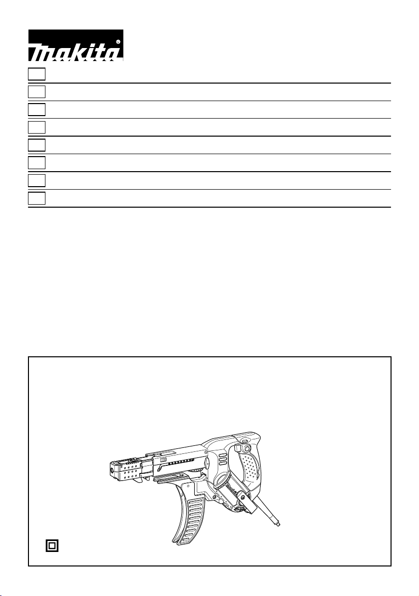
Auto Feed Screwdriver INSTRUCTION MANUAL
S
Skruvdragare med automatisk matning
N
Skrutrekker med automatisk mating BRUKSANVISNING
FIN
Autosyöttöinen ruuvinväännin KÄYTTÖOHJE
LV
Skrūvgriezis ar automātisku padevi LIETOŠANAS INSTRUKCIJA
LT
Atsuktuvas su automatiniu tiektuvu NAUDOJIMO INSTRUKCIJA
EE
Automaatse etteandega kruvikeeraja
RUS
Шуруповерт с автоподачей
BRUKSANVISNING
KASUTUSJUHEND
РУКОВОДСТВО ПО ЭКСПЛУАТАЦИИ
6842
6843
6844
1
Page 2

1 008104
1
2
4 008121
5mm
1
2
3
A
B
7 008124
1
A
2
2 008105
3
5 008122
2
8 008125
1
B
1
2
3 008108
1
2
1
4
2
3
6 008123
1
1
3
9 008126
10 008127
1
11 008128 12 008252
2
Page 3
1
13 008129 14 008130
1
2
1
16 001145
17 008144
1
15mm
2
15 004186
3
Page 4

ENGLISH
1-1. Lock button
1-2. Switch trigger
2-1. Reversing switch lever
3-1. Hook
3-2. Clamping screw
4-1. Casing
4-2. Thumb screw
5-1. Plane bearing
5-2. Dust cover
5-3. Bit
Explanation of general view
6-1. Lever
6-2. Stopper base
6-3. Label on feeder box
6-4. Fenestella
7-1. Stopper base
7-2. Casing
7-3. Adjusting knob
8-1. Feeder box
8-2. Screw strip
8-3. Screw guide
9-1. Driving position
11-1. Reverse button
13-1. Extension handle
15-1. Wall
15-2. Stopper base
16-1. Limit mark
17-1. Brush holder cap
17-2. Screwdriver
SPECIFICATIONS
Model 6842 6843 6844
Screw strip 4 mm x 25 mm - 55 mm
No load speed (min-1) 4,700 6,000 3,000
Overall length 400 mm 440 mm
Net weight 2.0 kg 2.1 kg
• Due to our continuing programme of research and development, the specifications herein are subject to change without notice.
• Note: Specifications may differ from country to country.
Symbols
The following show the symbols used for the equipment.
Be sure that you understand their meaning before use.
・ Read instruction manual.
・ DOUBLE INSULATION
・ Only for EU countries
Intended use
The tool is intended for screw driving in wood, metal and
plastic.
Power supply
The tool should be connected only to a power supply of
the same voltage as indicated on the nameplate, and
can only be operated on single-phase AC supply. They
are double-insulated in accordance with European
Standard and can, therefore, also be used from sockets
without earth wire.
Safety class /II
END201-3
For Model 6842, 6843
For European countries only
Noise
The typical A-weighted noise level determined according
to 60745-2-2:
Sound pressure level (L
Uncertainty (K) : 3 dB(A)
The noise level under working may exceed 85 dB (A).
Do not dispose of electric equipment
together with household waste material!
In observance of European Directive
2002/96/EC on waste electric and
electronic equipment and its
implementation in accordance with
national law, electric equipment that
have reached the end of their life must
be collected separately and returned to
an environmentally compatible
recycling facility.
ENE033-1
Vibration
The vibration total value (tri-axial vector sum)
determined according to EN60745-2-2:
Work mode: screwdriving without impact
Vibration emission (a
For Model 6844
For European countries only
Noise
The typical A-weighted noise level determined according
to 60745-2-2:
Sound pressure level (L
Uncertainty (K) : 3 dB(A)
ENF002-1
The noise level under working may exceed 85 dB (A).
Vibration
The vibration total value (tri-axial vector sum)
determined according to EN60745-2-2:
Work mode: screwdriving without impact
Vibration emission (a
pA
Wear ear protection.
) : 2.5 m/s2 or less
h
pA
Wear ear protection.
) : 2.5 m/s2 or less
h
4 mm x 45 mm - 75 mm
) : 84 dB(A)
) : 85 dB(A)
ENG101-1
ENG204-1
ENG101-1
ENG204-1
4
Page 5
ENH101-7
EC-DECLARATION OF CONFORMITY
Model; 6842, 6843, 6844
We declare under our sole responsibility that this
product is in compliance with the following standards of
standardized documents;
EN60745, EN55014, EN61000 in accordance with
Council Directives, 2004/108/EC, 98/37/EC.
CE2006
000230
Tomoyasu Kato
Director
Responsible Manufacturer:
Makita Corporation
3-11-8, Sumiyoshi-cho, Anjo, Aichi, JAPAN
Authorized Representative in Europe:
Makita International Europe Ltd.
Michigan Drive, Tongwell, Milton Keynes, Bucks MK15
8JD, ENGLAND
GEB017-1
SPECIFIC SAFETY RULES
DO NOT let comfort or familiarity with product
(gained from repeated use) replace strict adherence
to screwdriver safety rules. If you use this power
tool unsafely or incorrectly, you can suffer serious
personal injury.
1. Hold power tools by insulated gripping
surfaces when performing an operation where
the cutting tool may contact hidden wiring or
its own cord. Contact with a "live" wire will make
exposed metal parts of the tool "live" and shock
the operator.
2. Always be sure you have a firm footing.
Be sure no one is below when using the tool in
high locations.
3. Hold the tool firmly.
4. Keep hands away from rotating parts.
5. Do not touch the bit or the workpiece
immediately after operation; they may be
extremely hot and could burn your skin.
SAVE THESE INSTRUCTIONS.
WARNING:
MISUSE or failure to follow the safety rules stated in
this instruction manual may cause serious personal
injury.
FUNCTIONAL DESCRIPTION
CAUTION:
• Always be sure that the tool is switched off and
unplugged before adjusting or checking function on
the tool.
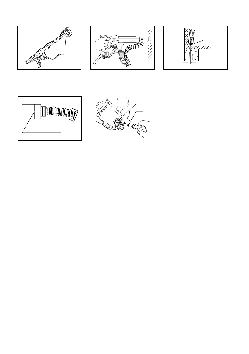
Switch action
Fig.1
CAUTION:
• Before plugging in the tool, always check to see
that the switch trigger actuates properly and
returns to the "OFF" position when released.
To start the tool, simply pull the switch trigger. Release
the switch trigger to stop.
For continuous operation, pull the switch trigger and
then push in the lock button.
To stop the tool from the locked position, pull the switch
trigger fully, then release it.
Reversing switch action
Fig.2
This tool has a reversing switch to change the direction
of rotation. Depress the reversing switch lever from the A
side for clockwise rotation or from the B side for
counterclockwise rotation.
CAUTION:
• Always check the direction of rotation before
operation.
• Use the reversing switch only after the tool comes
to a complete stop. Changing the direction of
rotation before the tool stops may damage the tool.
Hook
The hook is convenient for hooking the tool to your belt.
It can be installed on either side of the tool.
Changing the installation position of hook allows
two-way setting of 10 mm and 20 mm distance from the
tool itself.
The tool with hook can be hung on the waist belt, a
maximum diameter 20 mm pipe etc.
To remove the hook, just remove the clamping screw.
Place it on the tool and secure it with the clamping screw
to install.
Fig.3
ASSEMBLY
CAUTION:
• Always be sure that the tool is switched off and
unplugged before carrying out any work on the
tool.
Installing or removing the bit
Loosen the thumb screws which secure the casing. Pull
out the casing in the direction of the arrow.
Fig.4
Press the dust cover toward the plain bearing and pull
out the bit. If the dust cover cannot be moved as far as
the plain bearing, try it again after turning the bit slightly.
To install the bit, insert it into the socket while turning it
slightly. After installing, always make sure that the bit is
securely held in place by trying to pull it out.
5
Page 6

Fig.5
Setting for desired screw length
Fig.6
There are 7 positive-lock screw length settings. To
obtain the desired setting, pull out the stopper base
while depressing the lever until you see the number of
the desired screw length (indicated on the label on
feeder box) appear to rest in the fenestella of stopper
base. See the table below for the relation between the
number indicated on the label on feeder box and the
respective screw length.
For Models 6842, 6843
Number indicated on the label Screw length
25
30
35
40
45
50
55
008238
25 mm
30 mm
35 mm
40 mm
45 mm
50 mm
55 mm
For Model 6844
Number indicated on the label Screw length
008241
45
50
55
60
65
70
75
45 mm
50 mm
55 mm
60 mm
65 mm
70 mm
75 mm
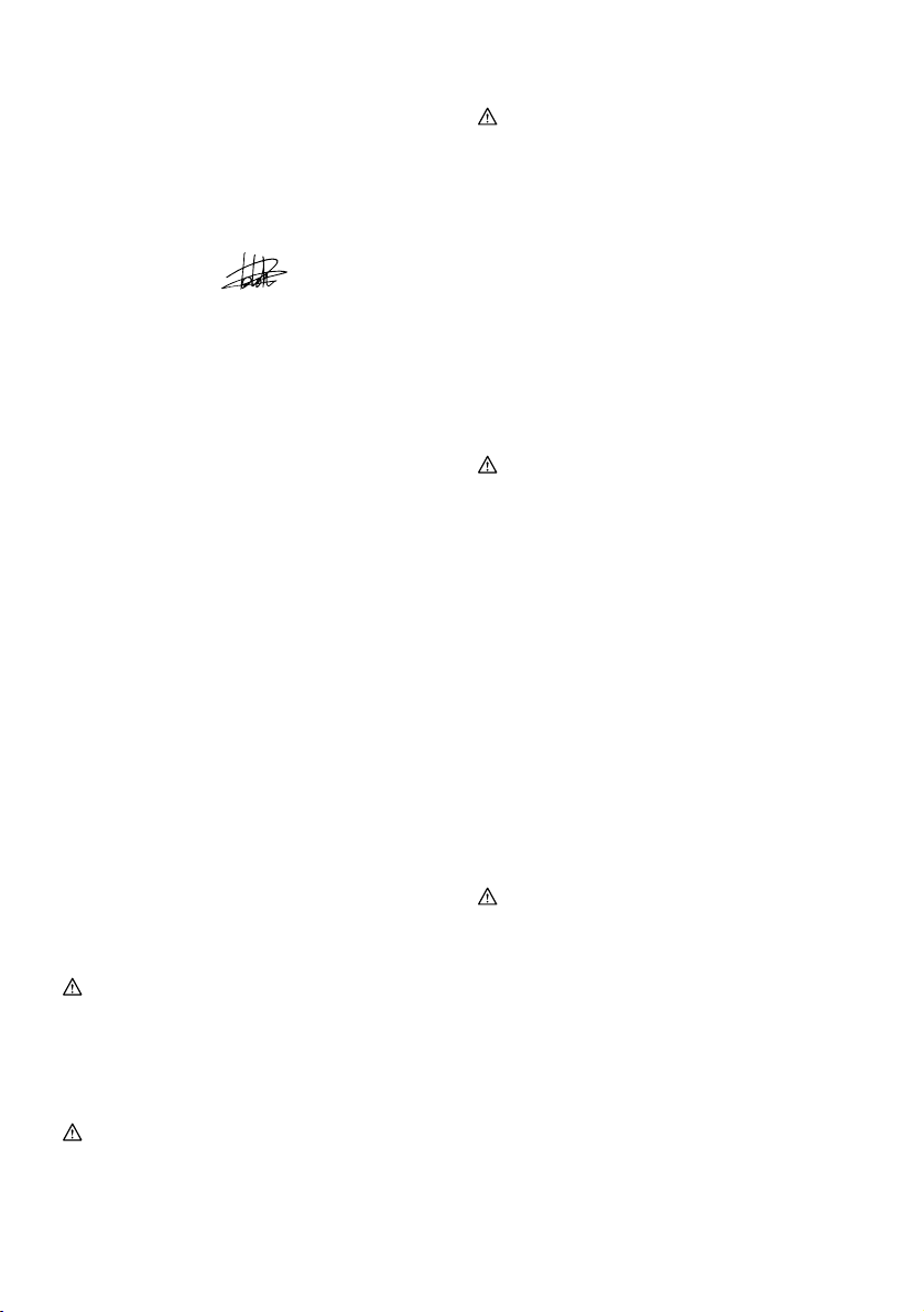
Adjusting the driving depth
Fig.7
Depress the stopper base as far as it will go. While
keeping it in this position, turn the adjusting knob until
the bit tip projects approx. 5 mm from the stopper base.
Drive a trial screw. If the screw head projects above the
surface of the workpiece, turn the adjusting knob in the
"A" direction; if the screw head is counter-sunk, turn the
adjusting knob in the "B" direction.
Installing screw strip
Insert the screw strip through the screw guide. Then
insert it through the feeder box until the first screw
reaches the position next to the driving position.
Fig.8
Fig.9
Removing screw strip
To remove the screw strip, just pull it out in the direction
of the arrow. If you depress the reverse button, you can
pull out the screw strip in the reverse direction of the
arrow.
Fig.10
Fig.11
Folding screw guide
Fig.12
Screw guide is foldable. Folding the screw guide allows
space used for storage to be minimal.
Extension handle (optional accessory)
Fig.13
Use of extension handle allows you to drive screws into
floors while standing.
OPERATION
Driving operation
Fig.14
Switch on the tool by pressing the switch trigger and at
the same time pushing the lock button. Hold the tool
squarely against the workpiece and apply forward
pressure to the tool. The screw will be automatically
carried to the driving position and driven into the
workpiece.
CAUTION:
• Always hold the tool squarely against the driving
surface. Holding it at an angle may damage the
screw heads and cause wear on the bit. This may
also lead to poor fastening.
• Always keep the tool firmly against the driving
surface until the driving is over. Failure to do so
may cause insufficient fastening of screws.
• Be careful not to drive a screw onto another screw
already fastened.
• Do not operate the tool without screws. It will
damage the driving surface.
Driving in corner
Fig.15
This tool can be used to drive at a position 15 mm away
from the wall as shown in the figure.
CAUTION:
• Driving at a position closer than 15 mm to the wall
or driving with the stopper base in contact with the
wall may damage the screw heads and cause wear
on the bit. This may also lead to poor fastening of
screws and malfunction of the tool.
MAINTENANCE
CAUTION:
• Always be sure that the tool is switched off and
unplugged before attempting to perform inspection
or maintenance.
6
Page 7

Replacing carbon brushes
Fig.16
Remove and check the carbon brushes regularly.
Replace when they wear down to the limit mark. Keep
the carbon brushes clean and free to slip in the holders.
Both carbon brushes should be replaced at the same
time. Use only identical carbon brushes.
Use a screwdriver to remove the brush holder caps.
Take out the worn carbon brushes, insert the new ones
and secure the brush holder caps.
Fig.17
To maintain product SAFETY and RELIABILITY, repairs,
any other maintenance or adjustment should be
performed by Makita Authorized Service Centers,
always using Makita replacement parts.
ACCESSORIES
CAUTION:
• These accessories or attachments are
recommended for use with your Makita tool
specified in this manual. The use of any other
accessories or attachments might present a risk of
injury to persons. Only use accessory or
attachment for its stated purpose.
If you need any assistance for more details regarding
these accessories, ask your local Makita Service Center.
• Phillips bit
• Drywall screw strips
• Extension handle
• Plastic carrying case
7
Page 8
SVENSKA
1-1. Låsknapp
1-2. Avtryckare
2-1. Reverseringsknapp
3-1. Krok
3-2. Låsskruv
4-1. Kåpa
4-2. Tumskruv
5-1. Lager
5-2. Dammkåpa
5-3. Bits
Förklaring till översiktsbilderna
6-1. Spak
6-2. Djupanslag
6-3. Etikett på matarhus
6-4. Öppning
7-1. Djupanslag
7-2. Kåpa
7-3. Inställningsknapp
8-1. Matarhus
8-2. Skruvband
8-3. Skruvguide
9-1. Skruvläget
11-1. Backknapp
13-1. Förlängningshandtag
15-1. Vägg
15-2. Djupanslag
16-1. Slitmarkering
17-1. Kolhållarlock
17-2. Skruvmejsel
SPECIFIKATIONER
Modell 6842 6843 6844
Skruvband 4 mm x 25 mm - 55 mm
Obelastat varvtal (min-1) 4 700 6 000 3 000
Längd 400 mm 440 mm
Vikt 2,0 kg 2,1 kg
• På grund av vårt pågående program för forskning och utveckling kan dessa specifikationer ändras utan föregående meddelande.
• Obs! Specifikationerna kan variera mellan olika länder.
Symboler
Följande visar symbolerna som används för
utrustningen. Se till att du förstår innebörden innan du
använder borrmaskinen.
・ Läs bruksanvisningen.
・ DUBBEL ISOLERING
・ Gäller endast inom EU
Intended use
Verktyget är avsett för skruvdragning i trä, metall och
plast.
Strömförsörjning
Maskinen får endast anslutas till nät med spänning som
anges på typplåten och med enfasig växelström. Den är
dubbelisolerad i enlighet med europeisk standard och
får därför också anslutas till ojordade vägguttag.
Säkerhetsklass /II
END201-3
För modell 6842, 6843
Gäller endast Europa
Buller
Typiska A-vägda bullernivåer är mätta enligt 60745-2-2:
Ljudtrycksnivå (L
Avvikelse (K): 3 dB(A)
Bullernivån under drift kan överstiga 85 dB(A).
Vibration
Elektrisk utrustning får inte kastas i
hushållsavfallet!
Enligt direktivet 2002/96/EC som avser
deponering av elektrisk och elektronisk
utrustning samt tillhörande föreskrifter i
det aktuella landets lagstiftning ska
uttjänt elektrisk utrustning sopsorteras
och lämnas till miljöstation för
återvinning.
ENE033-1
Det totala vibrationsvärdet (treaxlig vektorsumma)
bestämt enligt EN60745-2-2:
Arbetsläge: skruvdragning utan slag
Vibrationsemission (a
För modell 6844
Gäller endast Europa
Buller
Typiska A-vägda bullernivåer är mätta enligt 60745-2-2:
Ljudtrycksnivå (L
Avvikelse (K): 3 dB(A)
Bullernivån under drift kan överstiga 85 dB(A).
ENF002-1
Vibration
Det totala vibrationsvärdet (treaxlig vektorsumma)
bestämt enligt EN60745-2-2:
Arbetsläge: skruvdragning utan slag
Vibrationsemission (a
) : 84 dB(A)
pA
Använd hörselskydd.
): 2,5 m/s2 eller mindre
h
) : 85 dB(A)
pA
Använd hörselskydd.
): 2,5 m/s2 eller mindre
h
4 mm x 45 mm - 75 mm
ENG101-1
ENG204-1
ENG101-1
ENG204-1
8
Page 9
ENH101-7
EG-DEKLARATION OM
ÖVERENSSTÄMMELSE
Modell; 6842, 6843, 6844
Vi försäkrar under eget ansvar att denna produkt följer
de standarder som anges i följande standardiserade
dokument:
EN60745, EN55014, EN61000 i enlighet med direktiven
2004/108/EC, 98/37/EC.
CE2006
000230
Tomoyasu Kato
Direktör
Ansvarig tillverkare:
Makita Corporation
3-11-8, Sumiyoshi-cho, Anjo, Aichi, JAPAN
Auktoriserad representant i Europa:
Makita International Europe Ltd.
Michigan Drive, Tongwell, Milton Keynes, Bucks MK15
8JD, ENGLAND
GEB017-1
Specifika säkerhetsanvisningar
GLÖM INTE att strikt följa säkerhetsanvisningarna
för skruvdragaren efter att du blivit van att använda
den. Ovarsam eller felaktig användning av denna
elektriska maskin kan leda till allvarliga
personskador.
1. Elektriska maskiner ska hållas i de isolerade
handtagen när arbete utförs där skärverktyget
kan komma i kontakt med en dold elkabel eller
maskinens egen sladd. De synliga metalldelarna
på maskinen blir strömförande om maskinen
kommer I kontakt med en strömförande ledning
och användaren kan få en elstöt.
2. Se till att du hela tiden har ett säkert fotfäste.
Se till att ingen står under dig när maskinen
används på hög höjd.
3. Håll maskinen stadigt.
4. Håll händerna på avstånd från roterande delar.
5. Rör inte vid borr eller arbetsstycke omedelbart
efter användning eftersom de kan vara extremt
varma och orsaka brännskador.
SPARA DESSA ANVISNINGAR.
VARNING!
OVARSAM hantering eller användning som inte
följer säkerhetsanvisningarna i denna
bruksanvisning kan leda till allvarliga personskador.
9
FUNKTIONSBESKRIVNING
FÖRSIKTIGT!
• Se alltid till att maskinen är avstängd och
nätsladden urdragen innan du justerar eller
funktionskontrollerar maskinen.
Avtryckarens funktion
Fig.1
FÖRSIKTIGT!
• Innan du ansluter maskinen till elnätet ska du
kontrollera att avtryckaren fungerar och återgår till
läget "OFF" när du släpper den.
Tryck in avtryckaren för att starta maskinen. Släpp
avtryckaren för att stoppa den.
För oavbruten användning trycker du in avtryckaren och
därefter låsknappen.
Tryck in avtryckaren helt och släpp den sedan när du
inte längre vill använda det låsta läget.
Reverseringsknappens funktion
Fig.2
Denna maskin har en reverseringsknapp för att byta
rotationsriktning. Tryck in reverseringsknappen från
sidan A för medurs rotation och från sidan B för moturs
rotation.
FÖRSIKTIGT!
• Kontrollera alltid rotationsriktningen före
användning.
• Använd endast reverseringsknappen när maskinen
stannat helt. Maskinen kan skadas om du byter
rotationsriktning medan den fortfarande roterar.
Krok
Kroken är praktisk för att hänga verktyget i ditt bälte.
Den kan monteras på endera sidan av verktyget.
Ändring av krokens monteringsläge möjliggör två olika
inställningar, 10 mm och 20 mm avstånd från själva
verktyget.
Verktyget med krok kan hängas i bältet eller på ett rör
(max 20 mm i diameter) etc.
Avlägsna kroken genom att ta bort låsskruven. Placera
den på verktyget och fäst med låsskruven för att
montera.
Fig.3
MONTERING
FÖRSIKTIGT!
• Se alltid till att maskinen är avstängd och
nätsladden urdragen innan maskinen repareras.
Montering eller demontering av bits
Lossa vingskruvarna som fäster kåpan. Dra ut kåpan i
pilens riktning.
Page 10
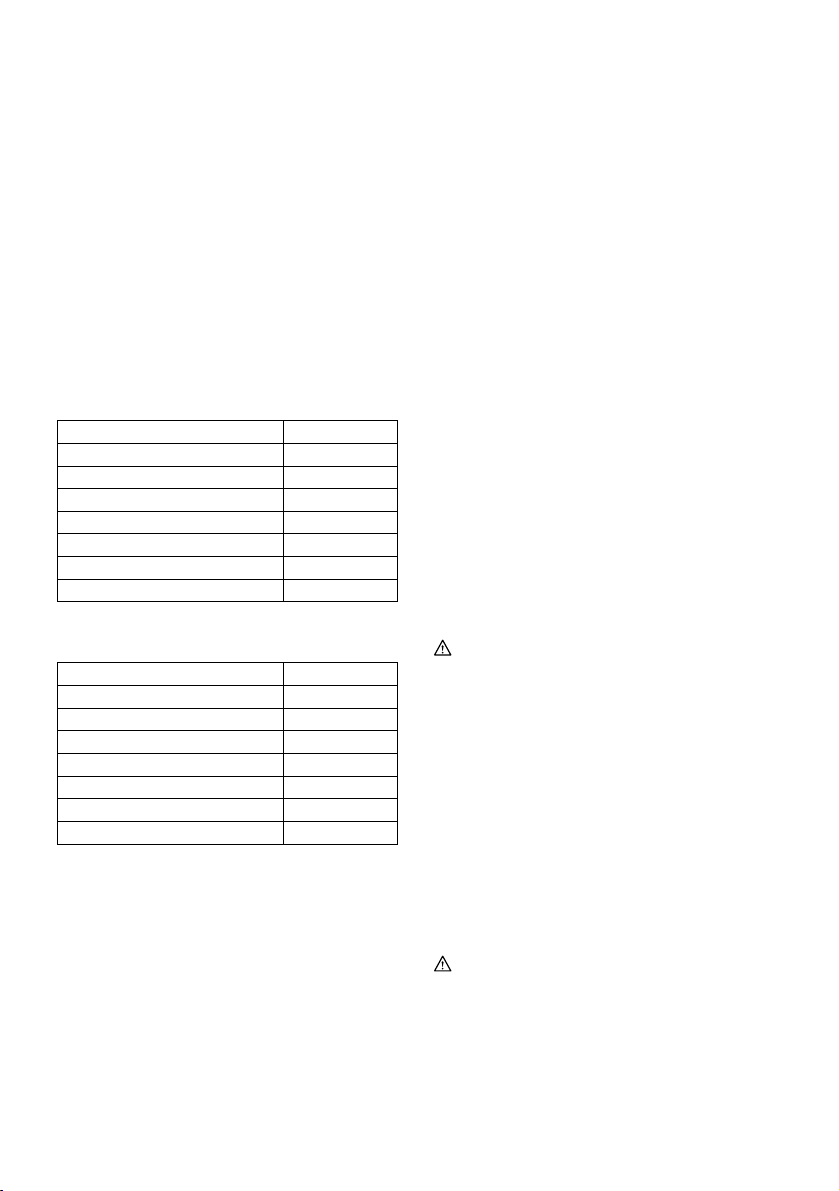
Fig.4
Tryck dammskyddet mot lagret och dra ut bitset. Vrid
bitset en aning om dammskyddet inte kan flyttas ända till
lagret och försök sedan igen.
Bitset monteras genom att föra in det i hylsan medan
den vrids runt en aning. Kontrollera alltid efter
monteringen att bitset är ordentligt fastsatt genom att
försöka dra ut det.
Fig.5
Inställning för önskad skruvlängd
Fig.6
Det finns 7 fasta inställningslägen för skruvlängden. Välj
önskad inställning genom att dra ut djupanslaget,
samtidigt som du trycker in reglaget, till önskad
skruvlängd (som anges på etiketten på matarhuset) som
syns i öppningen på djupanslaget. Nedanstående tabell
visar sambandet mellan numret som anges på etiketten
på matarhuset och respektive skruvlängd.
För modell 6842, 6843
Nummer som anges på etiketten Skruvlängd
25
30
35
40
45
50
55
008238
25 mm
30 mm
35 mm
40 mm
45 mm
50 mm
55 mm
För modell 6844
Nummer som anges på etiketten Skruvlängd
008241
45
50
55
60
65
70
75
45 mm
50 mm
55 mm
60 mm
65 mm
70 mm
75 mm
Inställning av borrdjup
Fig.7
Tryck in djupanslaget så långt det går. Medan du håller
kvar detta läge vrider du inställningsratten tills spetsen
på bitset sticker ut ca 5 mm från djupanslaget. Skruva i
en provskruv. Vrid inställningsratten i riktning A om
skruvhuvudet sticker ut från arbetsstyckets yta. Vrid
inställningsratten i riktning B om skruvhuvudet är
insjunket i arbetsstycket.
Montering av bandad skruv
Sätt i skruvbandet genom skruvguiden. Dra sedan
bandet genom matarhuset tills första skruven når läget
närmast skruvläget.
Fig.8
Fig.9
Demontering av skruvband
Ta bort skruvbandet genom att helt enkelt dra det i pilens
riktning. Tryck in reverseringsknappen om du vill dra ut
bandet i pilens motsatta riktning.
Fig.10
Fig.11
Hopvikbar skruvguide
Fig.12
Skruvguiden är hopvikbar. Den hopvikbara skruvguiden
ger minimalt förvaringsutrymme.
Förlängningshandtag (valfritt tillbehör)
Fig.13
Med förlängningshandtaget kan du dra i skruvar i golv
stående.
ANVÄNDNING
Användning
Fig.14
Slå på maskinen genom att trycka in avtryckaren
samtidigt som du trycker in låsknappen. Håll maskinen
vinkelrät mot arbetsstycket och tryck maskinen framåt.
Skruven kommer automatiskt att bli förd till skruvläget
och skruvas in i arbetsstycket.
FÖRSIKTIGT!
• Håll alltid maskinen vinkelrätt mot arbetsstyckets
yta. Att vinkla maskinen kan skada skruvhuvudet
och orsaka slitage på bitset. Det kan också leda till
dålig åtdragning.
• Håll alltid maskinen stadigt mot underlaget tills
iskruvningen är klar. Infästningen kan i annat fall bli
dålig.
• Var försiktig så att du inte skruvar på en plats där
det redan sitter en skruv.
• Använd inte verktyget utan skruvar. Det skadar
arbetsytan.
Skruvning i hörn
Fig.15
Det här verktyget kan användas för skruvdragning så
nära som 15 mm från en vägg, se figuren.
FÖRSIKTIGT!
• Skruvdragning på ett mindre avstånd än 15 mm
eller skruvdragning med djupanslaget i kontakt
med väggen, kan orsaka skador på skruvhuvudet
och slitage på bitset. Det kan också leda till att
skruven får sämre hållfasthet eller att maskinen
fungerar sämre.
10
Page 11

UNDERHÅLL
FÖRSIKTIGT!
• Se alltid till att maskinen är avstängd och
nätkabeln urdragen innan inspektion eller
underhåll utförs.
Byte av kolborstar
Fig.16
Ta bort och kontrollera kolborstarna regelbundet. Byt
dem när de är slitna ner till slitmarkeringen. Håll
kolborstarna rena så att de lätt kan glida in i hållarna.
Båda kolborstarna ska bytas ut samtidigt. Använd
endast identiska kolborstar.
Använd en skruvmejsel för att ta bort locken till
kolborstarna. Ta ur de utslitna kolborstarna, montera nya
och montera locken.
Fig.17
För att upprätthålla produktens SÄKERHET och
TILLFÖRLITLIGHET bör allt underhålls- och
justeringsarbete utföras av ett auktoriserat Makita
servicecenter och med reservdelar från Makita.
TILLBEHÖR
FÖRSIKTIGT!
• Dessa tillbehör och tillsatser rekommenderas för
användning tillsammans med den Makita-maskin
som denna bruksanvisning avser. Om andra
tillbehör eller tillsatser används kan det uppstå risk
för personskador. Använd endast tillbehören eller
tillsatserna för de syften de är avsedda för.
Kontakta ditt lokala Makita servicecenter om du behöver
ytterligare information om dessa tillbehör.
• Phillipsbits
• Bandad gipsskruv
• Förlängningshandtag
• Förvaringsväska av plast
11
Page 12

NORSK
1-1. Sperreknapp
1-2. Startbryter
2-1. Revershendel
3-1. Bøyle
3-2. Klemskrue
4-1. Hus
4-2. Fingerskrue
5-1. Glidelager
5-2. Støvdeksel
5-3. Bits
Oversiktsforklaring
6-1. Spak
6-2. Stopperfot
6-3. Etikett på materhuset
6-4. Avlesningsåpning
7-1. Stopperfot
7-2. Hus
7-3. Justeringsknott
8-1. Materhus
8-2. Skruebånd
8-3. Skrueføring
9-1. Innskruingsposisjon
11-1. Reversknapp
13-1. Forlengelseshåndtak
15-1. Vegg
15-2. Stopperfot
16-1. Utskiftingsmerke
17-1. Børsteholderhette
17-2. Skrutrekker
TEKNISKE DATA
Modell 6842 6843 6844
Skruebånd 4 mm x 25 mm - 55 mm
Ubelastet turtall (min-1) 4 700 6 000 3 000
Total lengde 400 mm 440 mm
Nettovekt 2,0 kg 2,1 kg
• Som følge av vårt kontinuerlige forsknings- og utviklingsprogram kan de tekniske dataene endres uten ytterligere forvarsel.
• Merk: Tekniske data kan variere fra land til land.
Symboler
Nedenfor ser du symbolene som brukes for dette
utstyret. Forviss deg om at du forstår hva de betyr, før du
begynner å bruke maskinen.
Beregnet bruk
Maskinen er beregnet til skruing i tre, metall og plast.
Strømforsyning
Maskinen må bare kobles til en strømkilde med samme
spenning som vist på typeskiltet, og kan bare brukes
med enfase-vekselstrømforsyning. Det er dobbelt
verneisolert i samsvar med europeiske standarder, og
kan derfor også brukes i kontakter uten jordledning.
Sikkerhetsklasse /II
END201-3
For modell 6842, 6843
Gjelder bare land i Europa
Støy
Typisk A-vektet lydtrykknivå er bestemt i henhold til
・ Les bruksanvisningen.
・ DOBBEL ISOLERING
60745-2-2:
Lydtrykknivå (L
Usikkerhet (K): 3 dB (A)
Støynivået under arbeid kan overskride 85 dB (A).
・ Bare for land i EU
Kast aldri elektroutstyr i
husholdningsavfallet!
I henhold til EU-direktiv 2002/96/EF om
kasserte elektriske og elektroniske
produkter og direktivets iverksetting i
nasjonal rett, må elektroutstyr som ikke
lenger skal brukes, samles separat og
returneres til et miljøvennlig
gjenvinningsanlegg
ENE033-1
Vibrasjon
Total vibrasjonsverdi (treakset vektorsum) beregnet i
samsvar med EN60745-2-2:
Arbeidsmodus: skrutrekking uten slag
Genererte vibrasjoner (a
For modell 6844
Gjelder bare land i Europa
Støy
Typisk A-vektet lydtrykknivå er bestemt i henhold til
60745-2-2:
ENF002-1
Lydtrykknivå (L
Usikkerhet (K): 3 dB (A)
Støynivået under arbeid kan overskride 85 dB (A).
Vibrasjon
Total vibrasjonsverdi (treakset vektorsum) beregnet i
samsvar med EN60745-2-2:
Arbeidsmodus: skrutrekking uten slag
Genererte vibrasjoner (a
) : 84 dB(A)
pA
Bruk hørselvern.
h
) : 85 dB(A)
pA
Bruk hørselvern.
h
4 mm x 45 mm - 75 mm
): 2,5 m/s2 eller mindre
): 2,5 m/s2 eller mindre
ENG101-1
ENG204-1
ENG101-1
ENG204-1
12
Page 13

ENH101-7
EUs SAMSVARS-ERKLÆRING
Modell; 6842, 6843, 6844
Vi tar det hele og fulle ansvar for at dette produktet
samsvarer med følgende standarder:
EN60745, NEK EN 55014 og NEK EN 61000 i
overensstemmelse med Rådsdirektivene 2004/108/EF
og 98/37/EF.
CE2006
000230
Tomoyasu Kato
Direktør
Ansvarlig produsent:
Makita Corporation
3-11-8, Sumiyoshi-cho, Anjo, Aichi, JAPAN
Autorisert representant i Europa:
Makita International Europe Ltd.
Michigan Drive, Tongwell, Milton Keynes, Bucks MK15
8JD, ENGLAND
GEB017-1
Spesifikke sikkerhetsregler
IKKE LA hensynet til hva som er "behagelig" eller
det faktum at du kjenner produktet godt (etter mange
gangers bruk) gjøre deg mindre oppmerksom på
sikkerhetsreglene for bruken av skrujernet. Hvis du
bruker dette elektriske verktøyet på en farlig eller
ukorrekt måte, kan du få alvorlige helseskader.
1. Hold elektroverktøy i de isolerte håndtakene
når du utfører en operasjon der skjærende
verktøy kan komme i kontakt med skjulte
ledninger eller ledningen til maskinen selv.
Kontakt med en strømførende ledning vil også
gjøre uisolerte deler av maskinen strømførende
og gi operatøren elektrisk støt.
2. Forviss deg alltid om at du har godt fotfeste.
Forviss deg om at ingen står under deg når du
jobber høyt over bakken.
3. Hold maskinen godt fast.
4. Hold hendene unna roterende deler.
5. Ikke berør bits eller arbeidsstykke umiddelbart
etter bruk. Disse vil da være ekstremt varme,
og du kan få brannsår.
TA VARE PÅ DISSE
INSTRUKSENE.
ADVARSEL:
MISBRUK av verktøyet eller mislighold av
sikkerhetsreglene i denne brukerhåndboken kan
resultere i alvorlige helseskader.
FUNKSJONSBESKRIVELSE
FORSIKTIG:
• Forviss deg alltid om at maskinen er slått av og
støpselet trukket ut av kontakten før du justerer
maskinen eller kontrollerer dens mekaniske
funksjoner.
Bryterfunksjon
Fig.1
FORSIKTIG:
• Før du kobler maskinen til strømnettet, må du alltid
kontrollere at startbryteren aktiverer maskinen på
riktig måte og går tilbake til "AV"-stilling når den
slippes.
For å starte maskinen må du ganske enkelt trykke på
startbryteren. Slipp startbryteren for å stoppe maskinen.
Når maskinen skal brukes kontinuerlig, må du trykke inn
startbryteren og så trykke på sperreknappen.
Hvis du vil stoppe verktøyet mens det er låst i
"PÅ"-stilling, må du klemme startbryteren helt inn og så
slippe den igjen.
Reverseringsfunksjon
Fig.2
Dette verktøyet har en reversbryter som kan brukes til å
endre rotasjonsretningen. Trykk inn reversbryteren fra
"A"-siden for å velge rotasjon med klokken, eller fra
"B"-siden for å velge rotasjon mot klokken.
FORSIKTIG:
• Før arbeidet begynner, må du alltid kontrollere
rotasjonsretningen.
• Bruk reversbryteren bare etter at verktøyet har
stoppet helt. Hvis du endrer rotasjonsretningen før
verktøyet har stoppet, kan det bli ødelagt.
Bøyle
Bøylen er praktisk når du skal henge verktøyet i beltet.
Den kan monteres på begge sider av verktøyet.
Endring av plasseringen av bøylen gjør det mulig med
en toveis innstilling på 10 mm og 20 mm avstand fra
selve verktøyet.
Verktøyet med bøylen kan henges i beltet, en pipe på
høyst 20 mm etc.
Ta av bøylen ved å ta av klemskruen. Fest den på
verktøyet med klemskruen.
Fig.3
MONTERING
FORSIKTIG:
• Forviss deg alltid om at maskinen er slått av og
støpselet trukket ut av kontakten før du utfører noe
arbeid på maskinen.
13
Page 14

Montere eller demontere bits
Løsne fingerskruene som holder huset. Trekk huset ut i
pilretningen.
Fig.4
Trykk støvdekselet mot glidelageret og trekk ut bitset.
Hvis støvdekslet ikke kan flyttes så langt som
glidelageret, må du prøve igjen etter at du har dreiet
bitset litt.
For å montere bitset, må du sette inn i pipen mens du
dreier den lett. Etter montering må du alltid forvisse deg
om at det sitter godt ved å prøve å trekke det ut.
Fig.5
Innstilling for ønsket skruelengde
Fig.6
Det er 7 skruelengdeinnstillinger med klikklås. For å få
ønsket innstilling må du trekke ut stopperfoten mens du
trykker inn hendelen, helt til tallet for ønsket
skruelengde (angitt på etiketten på materboksen) vises i
avlesningsåpningen på stopperfoten. Nedenstående
tabell viser forholdet mellom det tallet som er angitt på
etiketten på materboksen og de ulike skruelengdene.
For modellene 6842, 6843
Tall angitt på etikett Skruelengde
25 mm
30 mm
35 mm
40 mm
45 mm
50 mm
55 mm
008238
25
30
35
40
45
50
55
For modell 6844
Tall angitt på etikett Skruelengde
008241
45
50
55
60
65
70
75
45 mm
50 mm
55 mm
60 mm
65 mm
70 mm
75 mm
Justere skrudybden
Fig.7
Trykk inn stopperfoten så langt den går. Mens du holder
den i denne stillingen, dreier du justeringsknotten til
bitspissen stikker ca. 5 mm ut fra stopperfoten. Skru inn
en prøveskrue. Hvis skruehodet stikker opp over
overflaten på arbeidsemnet, må du dreie
justeringsknotten i A-retningen; hvis skruehodet blir
liggende lavere enn overflaten, må du dreie
justeringsknotten i B-retningen.
Montere skruebånd
Før skruebåndet inn gjennom skrueføringen. Før det
deretter inn gjennom matemekanismen til den første
skruen er ved siden av innskruingsposisjonen.
Fig.8
Fig.9
Fjerne skruebånd
Fjern skruebåndet ved å trekke det ut i pilretningen. Hvis
du trykker på reversknappen, kan du trekke ut
skruebåndet i motsatt retning av den pilen peker i.
Fig.10
Fig.11
Sammenleggbar skruefører
Fig.12
Skrueføreren er sammenleggbar. Ved å legge sammen
skrueføreren tar verktøyet mindre plass ved
oppbevaring.
Forlengelseshåndtak (valgfritt tilbehør)
Fig.13
Bruk av forlengelseshåndtak gjør det mulig for deg å
skru inn skruer i gulv mens du står.
BRUK
Skrutrekkerfunksjon
Fig.14
Slå på verktøyet ved å trykke på startbryteren og
låseknappen samtidig. Hold verktøyet i rett vinkel mot
arbeidsemnet og skyv det forover. Skruen føres
automatisk i posisjon og skrus inn i arbeidsemnet.
FORSIKTIG:
• Hold alltid verktøyet vinkelrett mot
arbeidsoverflaten. Hvis du holder maskinen i en
spissere vinkel, kan skruehodene bli ødelagt og
bitset bli slitt. Dette kan også føre til at skruene
ikke festes skikkelig.
• Hold alltid maskinen godt mot overflaten av
arbeidsemnet til skruoperasjonen er ferdig. Hvis
dette ikke gjøres, kan skruene bli dårlig festet.
• Vær forsiktig så du ikke forsøker å skru en ny
skrue inn i en som allerede er skrudd inn.
• Ikke bruk maskinen uten skruer. Dette vil ødelegge
emnet.
Skrutrekkerfunksjon i hjørner
Fig.15
Denne maskinen kan brukes til innskruing i en posisjon
som befinner seg 15 mm vekk fra veggen, som vist på
figuren.
FORSIKTIG:
• Innskruing i en posisjon nærmere enn 15 mm fra
veggen eller innskruing med stopperfoten på
14
Page 15

veggen kan ødelegge skruehodene og forårsake
slitasje på bitset. Dette kan også føre til dårlig
skruefeste og skader på maskinen.
VEDLIKEHOLD
FORSIKTIG:
• Forviss deg alltid om at maskinen er slått av og
støpselet trukket ut av kontakten før du foretar
inspeksjon eller vedlikehold.
Skifte kullbørster
Fig.16
Fjern og kontroller kullbørstene med jevne mellomrom.
Skift dem når de er slitt ned til utskiftingsmerket. Hold
kullbørstene rene og fri til å bevege seg i holderne.
Begge kullbørstene må skiftes samtidig. Bruk bare
identiske kullbørster.
Bruk en skrutrekker til å fjerne børsteholderhettene. Ta
ut de slitte kullbørstene, sett i nye, og fest
børsteholderhettene.
Fig.17
For å opprettholde produktets SIKKERHET og
PÅLITELIGHET, må reparasjoner, vedlikehold og
justeringer utføres av Makitas autoriserte servicesentre,
og det må alltid brukes reservedeler fra Makita.
TILBEHØR
FORSIKTIG:
• Det anbefales at du bruker dette tilbehøret eller
verktøyet sammen med den Makita-maskinen som
er spesifisert i denne håndboken. Bruk av annet
tilbehør eller verktøy kan forårsake helseskader.
Tilbehør og verktøy må kun brukes til det formålet
det er beregnet på.
Ta kontakt med ditt lokale Makita-servicesenter hvis du
trenger mer informasjon om dette tilbehøret.
• Phillips-bits
• Skruebånd for tørrvegg
• Forlengelseshåndtak
• Verktøykoffert av plast
15
Page 16

SUOMI
1-1. Lukituspainike
1-2. Liipaisinkytkin
2-1. Pyörimissuunnan vaihtokytkin
3-1. Koukku
3-2. Kiristysruuvi
4-1. Kotelo
4-2. Sormiruuvi
5-1. Tasolaakeri
5-2. Pölysuojus
5-3. Kärki
Yleisen näkymän selitys
6-1. Vipu
6-2. Pysäytinpohja
6-3. Syöttölaitteen laatikon etiketti
6-4. Fenestella
7-1. Pysäytinpohja
7-2. Kotelo
7-3. Säätönuppi
8-1. Syöttölaatikko
8-2. Ruuvivyö
8-3. Ruuviohjain
9-1. Kiinnityskohta
11-1. Suunnanvaihtonappi
13-1. Kahvanjatke
15-1. Seinä
15-2. Pysäytinpohja
16-1. Rajamerkki
17-1. Hiiliharjan pidikkeen kupu
17-2. Ruuvitaltta
TEKNISET TIEDOT
Malli 6842 6843 6844
Ruuvivyö 4 mm x 25 mm - 55 mm
Kuormittamaton nopeus (min-1) 4 700 6 000 3 000
Kokonaispituus 400 mm 440 mm
Nettopaino 2,0 kg 2,1 kg
Turvallisuusluokka /II
• Jatkuvan tutkimus- ja kehitysohjelman vuoksi pidätämme oikeuden muuttaa tässä mainittuja teknisiä ominaisuuksia ilman
ennakkoilmoitusta.
• Huomautus: Tekniset ominaisuudet saattavat vaihdella eri maissa.
Symbolit
Laitteessa on käytetty seuraavia symboleja. Varmista
ennen käyttöä, että ymmärrät niiden merkityksen.
・ Lue käyttöohjeet.
・ KAKSINKERTAINEN ERISTYS
・ Koskee vain EU-maita
Älä hävitä sähkötarvikkeita tavallisen
kotitalousjätteen mukana!
Vanhoja sähkö- ja elektroniikkalaitteita
koskevan EU-direktiivin 2002/96/ETY ja
sen maakohtaisten sovellusten
mukaisesti käytetyt sähkötarvikkeet on
toimitettava ongelmajätteen
keräyspisteeseen ja ohjattava
ympäristöystävälliseen kierrätykseen.
Käyttötarkoitus
Työkalu on tarkoitettu ruuvien kiinnittämiseen puuhun,
metalliin ja muoviin.
Virtalähde
Koneen saa kytkeä vain sellaiseen virtalähteeseen,
jonka jännite on sama kuin arvokilvessä ilmoitettu, ja sitä
saa käyttää ainoastaan yksivaiheisella vaihtovirralla.
Kone on kaksinkertaisesti suojaeristetty eurooppalaisten
standardien mukaisesti, ja se voidaan siten kytkeä myös
maadoittamattomaan pistorasiaan.
END201-3
ENE033-1
ENF002-1
Malli 6842, 6843
Vain Euroopan maissa
Melu
Tyypilliset A-painotetut melutasot ovat
määritelty60745-2-2 mukaan:
Äänenpainetaso (L
Horjuvuus (K): 3 dB(A)
) : 84 dB(A)
pA
Työskentelyn aikana melutaso voi ylittää 85 dB (A).
Käytä kuulosuojaimia.
Värähtely
Värähtelyn kokonaisarvo (kolmiakselisen vektorin
summa) on määritetty EN60745-2-2 mukaisesti:
Työtila: ruuvaus ilman vasarointia
Tärinäpäästö (a
Malli 6844
) : 2,5 m/s2 tai pienempi
h
Vain Euroopan maissa
Melu
Tyypilliset A-painotetut melutasot ovat
määritelty60745-2-2 mukaan:
Äänenpainetaso (L
Horjuvuus (K): 3 dB(A)
) : 85 dB(A)
pA
Työskentelyn aikana melutaso voi ylittää 85 dB (A).
Käytä kuulosuojaimia.
Värähtely
Värähtelyn kokonaisarvo (kolmiakselisen vektorin
summa) on määritetty EN60745-2-2 mukaisesti:
Työtila: ruuvaus ilman vasarointia
Tärinäpäästö (a
) : 2,5 m/s2 tai pienempi
h
16
4 mm x 45 mm - 75 mm
ENG101-1
ENG204-1
ENG101-1
ENG204-1
Page 17

VAKUUTUS EC-VASTAAVUUDESTA
ENH101-7
TOIMINTAKUVAUS
Malli; 6842, 6843, 6844
Makita ilmoittaa vastaavansa siitä, että tuote täyttää
seuraavien standardien vaatimukset;
EN60745, EN55014 ja EN61000 neuvoston direktiivien
2004/108/EY ja 98/37/EY mukaisesti.
CE2006
000230
Kytkimen toiminta
Kuva1
Tomoyasu Kato
Vastuullinen valmistaja:
Johtaja
Makita Corporation
3-11-8, Sumiyoshi-cho, Anjo, Aichi, JAPANI
Valtuutettu edustaja Euroopassa:
Makita International Europe Ltd.
Michigan Drive, Tongwell, Milton Keynes, Bucks MK15
8JD, ISO-BRITANNIA
GEB017-1
Erityiset turvasäännöt
ÄLÄ anna tuotteen helppokäyttöisyyden tai
tuttuuden (seuraa toistuvasta käytöstä) tuudittaa
Käynnistä työkalu painamalla liipaisinkytkintä. Laite
pysäytetään vapauttamalla liipaisinkytkin.
Jos haluat koneen käyvän jatkuvasti, paina ensin
liipaisinkytkin pohjaan ja paina sitten lukituspainiketta.
Kun haluat pysäyttää koneen jatkuvan käynnin, paina
liipaisinkytkin ensin pohjaan ja vapauta se sitten.
Pyörimissuunnan vaihtokytkimen toiminta
Kuva2
Työkalussa on pyörimissuunnan vaihtokytkin. Jos haluat
koneen pyörivän myötäpäivään, paina vaihtokytkintä
A-puolelta, ja jos vastapäivään, paina sitä B-puolelta.
sinua väärään turvallisuuden tunteeseen niin, että
laiminlyöt ruuvumeisselin turvaohjeiden
noudattamisen. Jos tätä sähkötyökalua käytetään
varomattomasti tai väärin, seurauksena voi olla
vakava henkilövahinko.
1. Pidä sähkötyökalua sen eristetyistä
tartuntapinnoista, jos terä voi osua piilossa
oleviin johtoihin tai koneen omaan
virtajohtoon. Osuminen jännitteiseen johtoon
saa paljaat metalliosat jännitteisiksi ja aiheuttaa
käyttäjälle sähköiskun.
2. Varmista aina, että seisot tukevasti.
Jos työskentelet korkealla, varmista, ettei
ketään ole alapuolella.
3. Pidä työkalua tiukasti.
4. Pidä kädet loitolla pyörivistä osista.
5. Älä kosketa kärkeä tai työkappaletta
välittömästi käytön jälkeen, sillä ne voivat olla
erittäin kuumia ja aiheuttaa palovammoja.
SÄILYTÄ NÄMÄ OHJEET.
Koukku
Koukulla voit kätevästi koukata työkalun vyöhöösi. Se
voidaan asentaa työkalun kummalle puolelle tahansa.
Koukun asennuspaikan vaihtamisella voit asettaa
kaksisuuntaisesti 10 mm:n ja 20 mm:n etäisyydet
työkalusta itsestään.
Koukulla varustettu työkalu voidaan koukata vyötärön
vyöhön, halkaisijaltaan enintään 20 mm:sen putken, jne.
Poistat koukun poistamalla ainoastaan kiristysruuvi.
Sijoita se työkaluun ja varmista se asennettavalla
kiristysruuvilla.
Kuva3
KOKOONPANO
VAROITUS:
VÄÄRINKÄYTTÖ tai tässä käyttöohjeessa
ilmoitettujen turvamääräysten laiminlyönti voi
aiheuttaa vakavia henkilövahinkoja.
Terän kiinnitys ja irrotus
Löysää koteloa kiinni pitävät sormiruuvit. Vedä kotelo
nuolen osoittamaan suuntaan.
Kuva4
Paina pölysuojusta kohti tasolaakeria ja vedä kärki irti.
Jos pölynsuojusta ei voi työntää niin pitkälle, kuin
tasolaakeria, yritä uudestaan sen jälkeen, kuin olet
17
HUOMAUTUS:
• Varmista aina ennen säätöjä tai tarkastuksia, että
laite on sammutettu ja irrotettu verkosta.
HUOMAUTUS:
• Tarkista aina ennen työkalun liittämistä
virtalähteeseen, että liipaisinkytkin kytkeytyy oikein
ja palaa asentoon OFF, kun se vapautetaan.
HUOMAUTUS:
• Tarkista aina pyörimissuunta ennen käyttöä.
• Käytä pyörimissuunnan vaihtokytkintä vasta sen
jälkeen, kun kone on lakannut kokonaan
pyörimästä. Pyörimissuunnan vaihto koneen vielä
pyöriessä voi vahingoittaa sitä.
HUOMAUTUS:
• Varmista aina, että laite on sammutettu ja irrotettu
virtalähteestä, ennen kuin teet sille mitään.
Page 18

kiertänyt terää hieman.
Asennat terän liittämällä se istukkaan samalla hieman
kiertämällä sitä. Varmista aina, että terä on kunnolla
kiinni yrittämällä vetää sitä irti.
Kuva5
Halutun ruuvinpituuden asentaminen
Kuva6
On olemassa 7 positiivisen lukon ruuvinpituusasetusta.
Saavuttaaksesi haluttu asetus vedä pysäytinjalusta ulos
samalla vipua alas painaen, kunnes näet halutun
ruuvinpituuden numeron (ilmaistu syöttölaitteen laatikon
etiketissä) joka ilmestyy pysäytinjalustan toisessa
fenestellassa. Katso alhaalla olevaa taulukkoa
syöttölaitteen laatikon etiketissä olevan numeron ja
kunkin ruuvin pituuden välisen suhteen vuoksi.
Malleille 6842, 6843
Etiketissä merkitty numero Ruuvin pituus
25
30
35
40
45
50
55
008238
25 mm
30 mm
35 mm
40 mm
45 mm
50 mm
55 mm
Malleille 6844
Etiketissä merkitty numero Ruuvin pituus
008241
45
50
55
60
65
70
75
45 mm
50 mm
55 mm
60 mm
65 mm
70 mm
75 mm
Ajosyvyyden säätö
Kuva7
Paina pysäytinalustaa niin pitkälle kuin se menee. Pidä
se tässä asennossa ja käännä säätönuppia, kunnes
kärki työntyy noin 5 mm esiin pysäytinalustasta. Kiinnitä
koeruuvi. Jos ruuvin kanta jää työkappaleen pinnan
yläpuolelle, käännä säätönuppia suuntaan A. Jos ruuvin
kanta työntyy liian syvälle, käännä säätönuppia
suuntaan B.
Ruuvausterän kiinnitys
Työnnä ruuvivyö ruuviohjaimen läpi. Työnnä vyö
seuraavaksi syöttölaatikon läpi, kunnes ensimmäinen
ruuvi tulee kiinnityskohtaa seuraavaan kohtaan.
Kuva8
Kuva9
Ruuvivyön irrottaminen
Irrota ruuvivyö vetämällä sitä nuolen osoittamaan
suuntaan. Jos painat suunnanvaihtonappia, ruuvivyö
voidaan vetää irti päinvastaiseen suuntaan kuin mihin
nuoli osoittaa.
Kuva10
Kuva11
Laskostusruuvin ohjain
Kuva12
Ruuvin ohjain on laskostettavissa. Ruuvin laskostamisen
avulla voit käyttää minimaalista käyttövarastoa.
Kahvanjatke (vaihtoehtoinen lisävaruste)
Kuva13
Kahvanjatketta käyttäen voit ajaa ruuveja lattiaan
seisten.
KÄYTTÖ
Ajotoiminta
Kuva14
Käynnistä työkalu painamalla liipaisinkytkintä ja samalla
lukkonappia painaen. Pidä työkalua suoraan
työkappaletta vastaan ja paina työkalua eteenpäin.
Ruuvi siirtyy automaattisesti ajoasentoon ja ajautuu
työkappaleeseen.
HUOMAUTUS:
• Paina kone aina kohtisuorassa asennossa
työkappaletta vasten. Jos koneella ruuvataan
vinosti, ruuvien kannat voivat vahingoittua ja
koneen kärki kulua. Ruuvit eivät ehkä myöskään
kiinnity kunnolla.
• Pidä kone aina ruuvauksen loppuun asti
työkappaletta vasten painettuna. Ruuvit eivät ehkä
kiinnity kunnolla, jos konetta ei pidetä painettuna
loppuun asti.
• Varo, ettet ruuvaa toista ruuvia jo kiinnitetyn ruuvin
päälle.
• Älä käytä konetta ilman ruuveja. Kone vaurioittaa
työkappaleen pintaa.
Kulmaan ajaminen
Kuva15
Tällä koneella voidaan kiinnittää ruuveja 15 mm päähän
seinistä kuvan osoittamalla tavalla.
HUOMAUTUS:
• Ruuvin kiinnittäminen alle 15 mm päähän seinästä
tai siten, että pysäytinalusta koskettaa seinää
saattaa vahingoittaa ruuvin kantaa ja aiheuttaa
terän kulumista. Ruuvit eivät ehkä myöskään
kiinnity kunnolla ja kone saattaa rikkoutua.
18
Page 19

HUOLTO
HUOMAUTUS:
• Varmista aina ennen tarkastuksia tai huoltotöitä,
että laite on sammutettu ja kytketty irti
virtalähteestä.
Hiiliharjojen vaihtaminen
Kuva16
Irrota ja tarkasta hiiliharjat säännöllisesti. Vaihda harjat,
kun ne ovat kuluneet rajamerkkiin asti. Pidä hiiliharjat
puhtaina ja varmista, että ne pääsevät liukumaan
vapaasti pidikkeissään. Molemmat hiiliharjat on
vaihdettava yhtä aikaa. Käytä vain identtisiä hiiliharjoja.
Irrota harjanpidikkeiden kuvut ruuvitaltalla. Irrota
kuluneet hiiliharjat, asenna uudet, ja kiinnitä pidikkeiden
kuvut.
Kuva17
Tuotteen TURVALLISUUDEN ja LUOTETTAVUUDEN
takaamiseksi korjaukset, muut huoltotyöt ja säädöt on
teetettävä Makitan valtuutetussa huoltopisteessä
Makitan varaosia käyttäen.
LISÄVARUSTEET
HUOMAUTUS:
• Seuraavia lisävarusteita tai laitteita suositellaan
käytettäväksi tässä ohjeessa kuvatun
Makita-työkalun kanssa. Muiden lisävarusteiden tai
laitteiden käyttö voi aiheuttaa vammautumisriskin.
Käytä lisävarustetta tai laitetta vain ilmoitettuun
käyttötarkoitukseen.
Jos tarvitset lisätietoja näistä lisävarusteista, ota yhteys
paikalliseen Makita-huoltopisteeseen.
• Ristiruuvauskärki
• Väliseinäruuvivyöt
• Kahvanjatke
• Muovinen kantolaukku
19
Page 20

LATVIEŠU
1-1. Fiksācijas poga
1-2. Slēdža mēlīte
2-1.
Griešanas virziena pārslēdzēja svira
3-1. Āķis
3-2. Spīlējuma skrūve
4-1. Ietvars
4-2. Spārnskrūve
5-1. Parastais gultnis
5-2. Putekļsargs
5-3. Urbis
Kopskata skaidrojums
6-1. Svira
6-2. Aiztura pamatne
6-3. Padeves ieliktņa marķējums
6-4. Lodziņš
7-1. Aiztura pamatne
7-2. Ietvars
7-3. Regulēšanas rokturis
8-1. Padevēja ieliktnis
8-2. Lentā savienotas skrūves
8-3. Skrūvju vadīkla
9-1. Skrūvēšanas stāvoklis
11-1. Pretējā virziena poga
13-1. Pagarinājuma rokturis
15-1. Siena
15-2. Aiztura pamatne
16-1. Robežas atzīme
17-1. Sukas turekļa vāks
17-2. Skrūvgriezis
SPECIFIKĀCIJAS
Modelis 6842 6843 6844
Lentā savienotas skrūves 4 mm x 25 mm - 55 mm
Apgriezieni minūtē bez slodzes (min-1) 4 700 6 000 3 000
Kopējais garums 400 mm 440 mm
Neto svars 2,0 kg 2,1 kg
• Dēļ mūsu nepārtrauktās pētniecības un izstrādes programmas, šeit dotās specifikācijas var mainīties bez brīdinājuma.
• Piezīme: Atkarība no valsts specifikācijas var atšķirties.
Simboli
Zemāk ir attēloti simboli, kas attiecas uz iekārtu. Pirms
darbarīka izmantošanas pārliecinieties, vai pareizi
izprotat to nozīmi.
・ Izlasiet rokasgrāmatu.
・ DUBULTA IZOLĀCIJA
・ Tikai ES dalībvalstīm
Paredzētā lietošana
Šis darbarīks ir paredzēts skrūvju ieskrūvēšanai kokā,
metālā un plastmasā.
Barošana
Šo instrumentu jāpieslēdz tikai datu plāksnītē uzrādītā
sprieguma barošanas avotam; to iespējams darbināt
tikai ar vienfāzes maiņstrāvas barošanu. Tiem ir
divkāršā izolācija saskaņā ar Eiropas standartu, tāpēc
tos var izmantot bez zemējuma.
Drošības klase /II
END201-3
Modelim 6842, 6843
Tikai Eiropas valstīm
Troksnis
Tipiskais A-svērtais trokšņa līmenis ir noteikts saskaņā
ar 60745-2-2:
Skaņas spiediena līmeni (L
Nenoteiktību (K) : 3 dB(A)
Darbības laikā trokšņa līmenis var pārsniegt 85 dB (A).
Neizmetiet elektriskās iekārtas kopā ar
mājturības atkritumiem!
Saskaņā ar Eiropas Direktīvas par
utilizējamo elektrisko un elektronisko
aparatūru 2002/96/EC prasībām un tās
īstenošanu saskaņā ar nacionālo
likumdošanu, elektriskās iekārtas to
kalpošanas laikā beigās ir jāsavāc
atsevišķi no citiem atkritumiem un
jānogādā atbilstošajā utilizācijas centrā.
ENE033-1
Vibrācija
Vibrāciju kopējais daudzums (trīs asu vektoru summa) ir
noteikts atbilstoši EN60745-2-2:
Darba režīms: skrūvēšana bez triecienrežīma
Vibrācijas izmeši (a
Modelim 6844
Tikai Eiropas valstīm
Troksnis
Tipiskais A-svērtais trokšņa līmenis ir noteikts saskaņā
ar 60745-2-2:
Skaņas spiediena līmeni (L
Nenoteiktību (K) : 3 dB(A)
ENF002-1
Darbības laikā trokšņa līmenis var pārsniegt 85 dB (A).
Vibrācija
Vibrāciju kopējais daudzums (trīs asu vektoru summa) ir
noteikts atbilstoši EN60745-2-2:
Darba režīms: skrūvēšana bez triecienrežīma
Vibrācijas izmeši (a
) : 84 dB(A)
pA
Lietojiet ausu aizsargus.
) : 2,5 m/s2 vai mazāk
h
) : 85 dB(A)
pA
Lietojiet ausu aizsargus.
) : 2,5 m/s2 vai mazāk
h
4 mm x 45 mm - 75 mm
ENG101-1
ENG204-1
ENG101-1
ENG204-1
20
Page 21

ENH101-7
EK ATBILSTĪBAS DEKLARĀCIJA
Modelis; 6842, 6843, 6844
Ar pilnu atbildību mēs paziņojam, ka šis izstrādājums
atbilst šādām normām un normatīvajiem dokumentiem,
EN60745, EN55014, EN61000 saskaņā ar Padomes
Direktīvām, 2004/108/EC, 98/37/EC.
CE2006
000230
Tomoyasu Kato
Direktors
Atbildīgais ražotājs:
Makita Corporation
3-11-8, Sumiyoshi-cho, Anjo, Aichi, JAPĀNA
Pilnvarotais pārstāvis Eiropā:
Makita International Europe Ltd.
Michigan Drive, Tongwell, Milton Keynes, Bucks MK15
8JD, ANGLIJA
GEB017-1
Papildus drošības noteikumi
NEZAUDĒJIET modrību darbarīka lietošanas laikā
(tas var gadīties pēc darbarīka daudzkārtējas
izmantošanas), rūpīgi ievērojiet skrūvgrieža
drošības noteikumus. Šī mehanizētā darbarīka
nedrošas vai nepareizas izmantošanas gadījumā var
gūt smagas traumas.
1. Darba laikā turiet mehanizētos darbarīkus aiz
izolētām virsmām, ja griezējinstruments var
pieskarties slēptam vadam zem sprieguma, vai
urbja vadam. Šāda saskarsme ar vadu zem
sprieguma var nodot spriegumu darbarīka metāla
daļām, un darba veicējs var saņemt elektrisko
triecienu.
2. Nodrošiniet, lai jums vienmēr būtu labs
atbalsts kājām.
Ja lietojat darbarīku augstumā, p
ārliecinieties,
ka apakšā neviena nav.
3. Turiet darbarīku stingri.
4. Turiet rokas tālu no rotējošām daļām.
5. Neskariet uzgali vai apstrādāto detaļu tūlīt pēc
darba veikšanas; tie var būt ļoti karsti un var
apdedzināt ādu.
SAGLABĀJIET ŠOS
NORĀDĪJUMUS.
BRĪDINĀJUMS:
NEPAREIZAS LIETOŠANAS vai šīs rokasgrāmatas
drošības noteikumu neievērošanas gadījumā var gūt
smagas traumas.
FUNKCIJU APRAKSTS
UZMANĪBU:
• Pirms regulējat vai pārbaudāt instrumenta darbību,
vienmēr pārliecinieties, vai instruments ir izslēgts
un atvienots no barošanas.
Slēdža darbība
Att.1
UZMANĪBU:
• Pirms instrumenta pieslēgšanas vienmēr
pārbaudiet, vai slēdža mēlīte darbojas pareizi un
atgriežas izslēgtā stāvoklī, kad tiek atlaista.
Lai ieslēgtu instrumentu, pavelciet slēdža mēlīti.
Atbrīvojiet mēlīti, lai apturētu.
Lai instruments darbotos nepārtraukti, pievelciet mēlīti
un nospiediet fiksācijas pogu.
Lai apturētu instrumentu, kad slēdzis fiksēts, pievelciet
mēlīti līdz galam, tad atlaidiet to.
Griešanās virziena pārslēdzēja darbība
Att.2
Šis darbarīks ir aprīkots ar pārslēdzēju, kas ļauj mainīt
griešanās virzienu. Nospiediet griešanās virziena
pārslēdzēja sviru no "A" puses rotācijai pulksteņrādītāja
virzienā vai no "B" puses rotācijai pretēji pulksteņrādītāja
virzienam.
UZMANĪBU:
• Pirms sākat strādāt vienmēr pārbaudiet griešanās
virzienu.
• Izmantojiet griešanās virziena pārslēdzēju tikai pēc
darbarīka pilnas apstāšanas. Griešanās virziena
maiņa pirms darbarīka pilnas apstāšanas var to
sabojāt.
Āķis
Āķis ir noderīgs, ja darbarīks ir jāaizāķē aiz jostas. To var
uzstādīt jebkurā darbarīka pusē.
Mainot āķa uzstādīšanas stāvokli, to iespējams uzstādīt
divējādi - 10 mm un 20 mm attālumā no darbarīka.
Darbarīku ar āķa palīdzību iespējams piekabināt pie
jostas, caurules ar maksimāli 20 mm lielu diametru un
citur.
Lai noņemtu āķi, vienkārši noskrūvējiet spīlējuma skrūvi.
Savukārt, lai āķi piestiprinātu, novietojiet to uz darbarīka
un pieskrūvējiet ar spīlējuma skrūvi.
Att.3
MONTĀŽA
UZMANĪBU:
• Vienmēr pārliecinieties, vai instruments ir izslēgts
un atvienots no barošanas, pirms veicat jebkādas
darbības ar instrumentu.
21
Page 22

Uzgaļa uzstādīšana vai noņemšana
Atskrūvējiet spārnskrūves, ar ko piestiprināts ietvars.
Izvelciet ietvaru bultiņas virzienā.
Att.4
Spiediet putekļu aizsargu parastā gultņa virzienā un
izvelciet uzgali ārā. Ja putekļu aizsargu nav iespējams
ievietot līdz parastajam gultnim, mēģiniet vēlreiz,
nedaudz pagriežot uzgali.
Lai uzstādītu uzgali, nedaudz pagriežot to, ievietojiet
uzgali galatslēgā. Pēc uzstādīšanas, mēģinot uzgali
izvilkt ārā, vienmēr pārliecinieties, vai tas stingri turas
tam paredzētajā vietā.
Att.5
Uzstādīšana vēlamajam skrūves garumam
Att.6
Var uzst ādīt 7 nekustīgās bloķēšanas skrūves garumus.
Lai uzstādītu vēlamajā garumā, nospiežot sviru, izvelciet
aiztura pamatni, līdz varat saskatīt vēlamā skrūves
garuma (norādīts padeves ieliktņa marķējumā) ciparu,
kas redzams aiztura pamatnes lodziņā. Skatiet turpmāk
redzamo tabulu, lai noskaidrotu sakarību starp ciparu,
kas norādīts padeves ieliktņa marķējumā, un attiecīgo
skrūves garumu.
Modelim 6842 un 6843
Marķējumā norādītais cipars Skrūvju garums
25
30
35
40
45
50
55
008238
25 mm
30 mm
35 mm
40 mm
45 mm
50 mm
55 mm
Modelim 6844
Marķējumā norādītais cipars Skrūvju garums
008241
45
50
55
60
65
70
75
45 mm
50 mm
55 mm
60 mm
65 mm
70 mm
75 mm
Skrūvēšanas dziļuma regulēšana
Att.7
Nospiediet aiztura pamatni līdz galam. Turot to šajā
stāvoklī, pagrieziet regulēšanas rokturi, līdz uzgaļa gals
izvirzās no aiztura pamatnes par apmēram 5 mm.
Ieskrūvējiet pārbaudes skrūvi. Ja skrūves galviņa
izvirzās virs apstrādājamā materiāla virsmas, pagrieziet
regulēšanas rokturi "A" virzienā; ja skrūves galviņa ir
iegrimusi, pagrieziet regulēšanas rokturi "B" virzienā.
Lentā savienotu skrūvju uzstādīšana
Ievietojiet lentā savienotās skrūves caur skrūvju vadīklu.
Pēc tam to ievietojiet caur padeves ieliktni, līdz pirmā
skrūve atrodas stāvoklī, kas ir blakus skrūvēšanas
stāvoklim.
Att.8
Att.9
Lentā savienotu skrūvju noņemšana
Lai noņemtu lentā savienotās skrūves, izvelciet tās
bultiņas virzienā. Ja nospiedīsiet pretējā virziena pogu,
lentā savienotās skrūves varēsiet izvilkt bultiņai pretējā
virzienā.
Att.10
Att.11
Salokāma skrūvju vadīkla
Att.12
Skrūvju vadīkla ir salokāma. Salokot skrūvju vadīklu, to
glabāšanai vajag minimālu vietu.
Pagarinājuma rokturis (papildpiederums)
Att.13
Izmantojot pagarinājuma rokturi, varēsiet skrūves
ieskrūvēt grīdā, stāvot kājās.
EKSPLUATĀCIJA
Skrūvēšana
Att.14
Nospiežot slēdža mēlīti un tajā pašā laikā spiežot
bloķēšanas pogu, iedarbiniet darbarīku. Turiet darbarīku
paralēli detaļai un uzspiediet uz darbarīka virzienā uz
priekšu. Skrūve tiks automātiski novietota skrūvēšanas
stāvoklī un ieskrūvēta detaļā.
UZMANĪBU:
• Vienmēr turiet darbarīku paralēli skrūvējamajai
virsmai. Turot to leņķī, skrūves galviņas var tikt
sabojātas un uzgalis var nodilt. Rezultātā arī
stiprinājums var būt pārāk mazs.
• Vienmēr stingri turiet darbarīku pret skrūvējamo
virsmu, līdz skrūvēšana ir pabeigta. Ja šādi
nerīkosieties, skrūves var nebūt pietiekami cieši
pieskrūvētas.
• Uzmanieties, lai neuzskrūvētu skrūvi virsū citai
pieskrūvētai skrūvei.
• Nedarbiniet darbarīku, ja tajā nav skrūvju.
Rezultātā skrūvējamā virsma būs bojāta.
Skrūvēšana stūrī
Att.15
Šo darbarīku var izmantot skrūvēšanai 15 mm attālumā
no sienas, kā attēlots zīmējumā.
22
Page 23

UZMANĪBU:
• Skrūvējot stāvoklī, kas ir tuvāk par 15 mm no
sienas, vai skrūvējot, kad aiztura pamatne
pieskaras sienai, skrūves galviņas var sabojāt, un
uzgalis var nodilt. Rezultātā arī skrūvju
stiprinājums var būt pārāk mazs, un darbarīks var
sabojāties.
APKOPE
UZMANĪBU:
• Pirms veicat pārbaudi vai apkopi vienmēr
pārliecinieties, vai instruments ir izslēgts un
atvienots no barošanas.
Ogles suku nomaiņa
Att.16
Regulāri izņemiet un pārbaudiet ogles sukas. Kad ogles
sukas ir nolietojušās līdz robežas atzīmei, nomainiet tās.
Turiet ogles sukas tīras un pārbaudiet, vai tās var brīvi
ieiet turekļos. Abas ogles sukas ir jānomaina vienlaikus.
Izmantojiet tikai identiskas ogles sukas.
Noņemiet sukas turekļa vāciņus ar skrūvgrieža palīdzību.
Izņemiet nolietojušās ogles sukas, ievietojiet jaunas un
nostipriniet sukas turekļa vāciņus.
Att.17
Lai saglabātu produkta DROŠU un UZTICAMU darbību,
remontdarbus, apkopi un regulēšanu uzticiet veikt tikai
Makita pilnvarotam apkopes centram un vienmēr
izmantojiet tikai Makita rezerves daļas.
PIEDERUMI
UZMANĪBU:
• Šādi piederumi un rīki tiek ieteikti lietošanai ar šajā
pamācībā aprakstīto Makita instrumentu. Jebkādu
citu piederumu un rīku izmantošana var radīt
traumu briesmas. Piederumu vai rīku izmantojiet
tikai tā paredzētajam mērķim.
Ja jums vajadzīga palīdzība vai precīzāka informācija
par šiem piederumiem, vērsieties savā tuvākajā Makita
apkopes centrā.
• Krustveidīgs uzgalis
• Lentās savienotas skrūves sausam mūrim
• Pagarinājuma rokturis
• Plastmasas pārnēsāšanas soma
23
Page 24

LIETUVIŲ KALBA
1-1. Fiksuojamasis mygtukas
1-2. Jungiklio spraktukas
2-1. Atbulinės eigos jungiklio svirtelė
3-1. Kablys
3-2. Suveržimo varžtas
4-1. Gaubtas
4-2. Varžtas praplatinta galvute
5-1. Slydimo guolis
5-2. Gaubtelis nuo dulkių
5-3. Grąžtas
Bendrasis aprašymas
6-1. Svirtelė
6-2. Stabdiklio pagrindas
6-3. Tiektuvo dėžutės plokštelė
6-4. Apvalus gaubtelis
7-1. Stabdiklio pagrindas
7-2. Gaubtas
7-3. Reguliavimo rankenėlė
8-1. Tiektuvo dėžutė
8-2. Varžtų juosta
8-3. Varžtų kreiptuvas
9-1. Sukimo padėtis
11-1. Atbulinės eigos mygtukas
13-1. Pailginimo rankena
15-1. Siena
15-2. Stabdiklio pagrindas
16-1. Ribos žymė
17-1. Šepetėlio laikiklio dangtelis
17-2. Atsuktuvas
SPECIFIKACIJOS
Modelis 6842 6843 6844
Var žtų juosta 4 mm x 25 mm - 55 mm
Greitis be apkrovos (min.-1) 4 700 6 000 3 000
Bendras ilgis 400 mm 440 mm
Neto svoris 2,0 kg 2,1 kg
Saugos klasė /II
• Atliekame nepertraukiamus tyrimus ir nuolatos tobuliname savo gaminius, todėl čia pateikiamos specifikacijos gali būti keičiamos be
įspėjimo.
• Pastaba: įvairiose šalyse specifikacijos gali skirtis.
Simboliai
Žemiau yra nurodyti įrangai naudojami simboliai. Prieš
naudodami įsitikinkite, kad suprantate jų reikšmę.
・ Perskaitykite instrukciją.
・ DVIGUBA IZOLIACIJA
・ Tik ES šalims
Neišmeskite elektrinės įrangos kartu su
buitinėmis šiukšlėmis!
Pagal Europos Direktyvą 2002/96/EC
dėl elektros ir elektroninės įrangos
atliekų ir jos vykdymą pagal vietinius
įstatymus, elektrinė įranga , pasibaigus
jos eksploatacijos laikui, turi būti atskirai
surenkama ir nusiųsta į ekologiškai
suderinamą perdirbimo gamyklą.
Paskirtis
Šis įrankis skirtas sukti varžtams medienoje, metale ir
plastmasėje.
Elektros energijos tiekimas
Įrenginiui turi būti tiekiama tokios įtampos elektros
energija, kaip nurodyta duomenų lentelėje; įrenginys
veikia tik su vienfaze kintamąja srove. Visi įrenginiai turi
dvigubą izoliaciją, kaip reikalauja Europos standartas,
todėl juos galima jungti į elektros lizdą neįžemintus.
END201-3
ENE033-1
ENF002-1
Modeliui 6842, 6843
Tik Europos šalims
Triukšmas
Bûdingas A-svertinis triukðmo lygis, nustatytas pagal
60745-2-2:
Garso slėgio lygis (L
Paklaida (K): 3 dB (A)
) : 84 dB (A)
pA
Triukšmo lygis darbo metu gali viršyti 85 dB (A).
Dėvėkite ausų apsaugą.
Vibracija
Bendras vibracijos dydis (erdvinio vektoriaus suma),
nustatytas pagal EN60745-2-2 reikalavimus:
Darbo režimas: sukimas be smūgių
Vibracijos skleidimas (a
Modeliui 6844
): 2,5 m/s2 arba mažiau
h
Tik Europos šalims
Triukšmas
Bûdingas A-svertinis triukðmo lygis, nustatytas pagal
60745-2-2:
Garso slėgio lygis (L
Paklaida (K): 3 dB (A)
) : 85 dB (A)
pA
Triukšmo lygis darbo metu gali viršyti 85 dB (A).
Dėvėkite ausų apsaugą.
Vibracija
Bendras vibracijos dydis (erdvinio vektoriaus suma),
nustatytas pagal EN60745-2-2 reikalavimus:
Darbo režimas: sukimas be smūgių
Vibracijos skleidimas (a
): 2,5 m/s2 arba mažiau
h
24
4 mm x 45 mm - 75 mm
ENG101-1
ENG204-1
ENG101-1
ENG204-1
Page 25

ENH101-7
ES ATITIKIMO DEKLARACIJA
Modelis; 6842, 6843, 6844
Mes atsakingai tvirtiname, kad šis gaminys atitinka
žemiau nurodytus standartizuotų dokumentų
reikalavimus;
EN60745, EN55014, EN61000 pagal Tarybos
Direktyvos, 2004/108/EC, 98/37/EC.
CE2006
000230
Tomoyasu Kato
Direktorius
Atsakingasis gamintojas:
Makita Corporation
3-11-8, Sumiyoshi-cho, Anjo, Aichi, JAPAN (JAPONIJA)
Įgaliotasis atstovas Europoje:
Makita International Europe Ltd.
Michigan Drive, Tongwell, Milton Keynes, Bucks MK15
8JD, ENGLAND (ANGLIJA)
GEB017-1
Konkrečios saugos taisyklės
NELEISKITE, kad patogumas ir gaminio pažinimas
(įgyjamas pakartotinai naudojant) susilpnintų griežtą
darbo su atsuktuvu laikymąsi. Jei naudosite šį
elektrinį įrankį nesaugiai ar neteisingai, galite rimtai
susižeisti.
1. Laikykite elektrinius įrankius už izoliuotų
suėmimui skirtų vietų, kai jį naudojate ten, kur
pjaunantis įrankis gali susiliesti su laidais ar jo
paties laidu. Kontaktas su laidu su įtampa
perduos įtampą neuždengtoms metalinėms
įrankio dalims ir paveikti įrankio naudotoją.
2. Visuomet stovėkite tvirtai.
Įsitikinkite, kad po jumis nieko nėra, jei dirbate
aukštai.
3. Tvirtai laikykite įrankį.
4. Laikykite rankas toliau nuo sukamųjų dalių.
5. Nelieskite grąžto arba ruošinio iškart po
naudojimo; jie gali būti itin karšti ir nudeginti
odą.
SAUGOKITE ŠIAS
INSTRUKCIJAS.
ĮSPĖJIMAS:
Dėl NETINKAMO NAUDOJIMO arba saugos taisyklių
nesilaikymo, kurios pateiktos šioje instrukcijoje
galima rimtai susižeisti.
VEIKIMO APRAŠYMAS
DĖMESIO:
• Prieš reguliuodami įrenginį arba tikrindami jo
veikimą visada patikrinkite, ar įrenginys išjungtas,
o laido kištukas - ištrauktas iš elektros lizdo.
Jungiklio veikimas
Pav.1
DĖMESIO:
• Prieš jungdami įrenginį visada patikrinkite, ar
jungiklis gerai įsijungia, o atleistas grįžta į padėtį
OFF (išjungta).
Įrenginys įjungiamas tiesiog patraukiant jungiklio svirtį.
Įrenginys išjungiamas atleidus jungiklio svirtį.
Kad įrenginys neišsijungtų, reikia patraukti jungiklio
spragtuką ir paspausti fiksuojamąjį mygtuką.
Jeigu norite, kad įrenginio jungiklis nebūtų užfiksuotas,
jo mygtuką patraukite iki galo ir atleiskite.
Atbulinės eigos jungimas
Pav.2
Šis įrankis turi atbulinės eigos jungiklį sukimosi krypčiai
keisti. Nuspauskite atbulinės eigos jungiklio svirtelę iš
pusės A, kad suktųsi pagal laikrodžio rodyklę, arba iš B
pusės, kad suktųsi prieš laikrodžio rodyklę.
DĖMESIO:
• Prieš naudodami visuomet patikrinkite sukimosi
kryptį.
• Atbulinės eigos jungiklį naudokite tik įrankiui
visiškai sustojus. Jei keisite sukimosi kryptį prieš
įrankiui sustojant, galite pažeisti įrankį.
Kablys
Kablys patogus įrankiui prie diržo prikabinti. Jį galima
pritaisyti bet kurioje įrankio pusėje.
Keičiant kablio pritaisymo padėtį, jį galima nustatyti 10
mm arba 20 mm atstumu nuo paties įrankio.
Įrankį su kabliu galima pakabinti ant liemens diržo;
maksimalus vamzdelio skersmuo - 20 mm ir t.t.
Norėdami nuimti kablį, tiesiog išsukite suveržimo varžtą.
Norėdami pritaisyti kablį, priveržkite jį prie įrankio
suveržimo varžtu.
Pav.3
SURINKIMAS
DĖMESIO:
• Prieš taisydami įrenginį visada patikrinkite, ar jis
išjungtas, o laido kištukas - ištrauktas iš elektros
lizdo.
Grąžto įdėjimas ir išėmimas
Atsukite gaubtelį laikančias sparnuotąsias veržles.
Ištraukite gaubtelį rodyklės kryptimi.
25
Page 26

Pav.4
Spauskite dulkių gaubtelį link slenkamo guolio ir
ištraukite grąžtą. Jeigu dulkių gaubtelio link slenkamo
guolio pastumti nepavyksta, truputį pasukite grąžtą ir
pabandykite dar kartą.
Norėdami įdėti grąžtą, įkiškite jį į lizdą, truputį jį
pasukdami. Įdėję, visada patikrinkite, ar grąžtas įdėtas
tvirtai, pabandydami jį ištraukti.
Pav.5
Norimo varžto ilgio nustatymas
Pav.6
Galima pasirinkti vieną iš 7 teigiamų fiksuojamų varžto
ilgio nustatymų. Norėdami nustatyti norimą ilgį,
laikydami nuspaudę svirtelę, traukite fiksatoriaus
pagrindą, kol ant fiksatoriaus pagrindo gaubtelio krašto
pamatysite norimo varžto ilgio skaičių (pažymėtą ant
tiektuvo dėžės plokštelės). Žr. į toliau pateiktą lentelę,
kurioje nurodytas tiektuvo dėžės plokštelėje nurodyto
skaičiaus ir atitinkamo varžto ilgio atitikmuo.
6842 ir 6843 modeliams
Plokštelėje nurodytas skaičius Varžto ilgis
25
30
35
40
45
50
55
008238
25 mm
30 mm
35 mm
40 mm
45 mm
50 mm
55 mm
6844 modeliui
Plokštelėje nurodytas skaičius Varžto ilgis
008241
45
50
55
60
65
70
75
45 mm
50 mm
55 mm
60 mm
65 mm
70 mm
75 mm
Sukimo gylio reguliavimas
Pav.7
Iki galo nuspauskite fiksatoriaus pagrindą. Laikydami jį
tokioje padėtyje, sukite reguliavimo rankenėlę, kol grąžto
galiukas iš fiksatoriaus pagrindo išsikiš maždaug 5 mm.
Įsukite bandomąjį varžtą. Jeigu varžto galvutė išsikiša
virš medžiagos paviršiaus, pasukite reguliavimo
rankenėlę A kryptimi; jeigu varžto galvutė yra per daug
įsukta į medžiagą, sukite reguliavimo rankenėlę B
kryptimi.
Nustatomosios plokštės įtaisymas
Pro suktuvo kreiptuvą prakiškite nustatomąją plokštę. Po
to kiškite ją pro tiektuvo dėžutę, kol pirmasis varžtas
atsidurs beveik sukimo padėtyje.
Pav.8
Pav.9
Nustatomosios plokštės nuėmimas
Norėdami išimti nustatomąją juostą, tiesiog traukite ją
rodyklės kryptimi. Jeigu nuspausite atbulinės eigos
mygtuką, galėsite ištraukti nustatomąją plokštę preišinga
rodyklei kryptimi.
Pav.10
Pav.11
Sudedamas varžtų kreiptuvas
Pav.12
Var žt ų kreiptuvą galima sulankstyti. Sudedamas varžtų
kreiptumas leidžia maksimaliai sumažinti įrankiui skirtą
laikymo vietą.
Pailginimo rankenėlė (papildomas įtaisas)
Pav.13
Pailginimo rankenėlė leidžia stovint sukti varžtus į
grindis.
NAUDOJIMAS
Varžtų įsukimo operacija
Pav.14
Nuspaudę gaiduką ir tuo pačiu metu spausdami
fiksavimo mygtuką, įjunkite įrankį. Laikykite įrankį
statmenai ruošiniui ir paspauskite įrankį į priekį. Varžtas
automatiškai bus nustatytas į sukimo padėtį ir įsuktas į
ruošinį.
DĖMESIO:
• Įrankį laikykite statmenai ruošinio paviršiui. Laikant
jį kampu, galima sugadinti varžtų galvutes, gali
greičiau nusidėvėti grąžtas. Be to, gali būti prastai
sukami varžtai.
• Iki pat sukimo pabaigos, tvirtai laikykite įrėmę įrankį
į ruošinio paviršių. Jeigu to nedarysite, varžtai bus
įsukami nepakankamai.
• Būkite atsargūs, kad nepradėtumėte sukti varžto
toje veitoje, kur jau įsuktas itas varžtas.
• Nenaudokite įrankio be varžtų. Sugadinsite
ruošinio paviršių.
Sukimas į kampą
Pav.15
Šiuo įrankiu galima sukti 15 mm atstumu nuo sienos,
kaip parodyta paveikslėlyje.
DĖMESIO:
• Sukant arčiau nei 15 mm nuo sienos arba kai
fiksatoriau pagrindas liečia sieną, varžtų galvutės
gali būti sugadintos, gali susidėvėti ir sukimo
antgalis. Be to, varžtai gali būti įsukami prastai, gali
blogai veikti įrankis.
26
Page 27

TECHNINĖ PRIEŽIŪRA
DĖMESIO:
• Prieš apžiūrėdami ar taisydami įrenginį visada
patikrinkite, ar jis išjungtas, o laido kištukas ištrauktas iš elektros lizdo.
Anglinių šepetėlių keitimas
Pav.16
Periodiškai išimkite ir patikrinkite anglinius šepetėlius.
Pakeiskite juos, kai nusidėvi iki ribos žymės. Laikykite
anglinius šepetėlius švarius ir laisvai įslenkančius į
laikiklius. Abu angliniai šepetėliai turėtų būti keičiami tuo
pačiu metu. Naudokite tik identiškus anglinius
šepetėlius.
Jei norite nuimti šepetėlių laikiklių dangtelius,
pasinaudokite atsuktuvu. Išimkite sudėvėtus anglinius
šepetėlius, įdėkite naujus ir įtvirtinkite šepetėlį laikiklio
dangtelį.
Pav.17
Kad gaminys būtų SAUGUS ir PATIKIMAS, jį taisyti,
apžiūrėti ar vykdyti bet kokią kitą priežiūrą ar derinimą
turi įgaliotasis kompanijos „Makita" techninės priežiūros
centras; reikia naudoti tik kompanijos „Makita"
pagamintas atsargines dalis.
PRIEDAI
DĖMESIO:
• Su šiame vadove aprašytu įrenginiu „Makita"
rekomenduojama naudoti tik nurodytus priedus ir
papildomus įtaisus. Jeigu bus naudojami kitokie
priedai ar papildomi įtaisai, gali būti sužaloti
žmonės. Priedus arba papildomus įtaisus
naudokite tik pagal paskirtį.
Jeigu norite daugiau sužinoti apie tuos priedus,
kreipkitės į artimiausią „Makita" techninės priežiūros
centrą.
• Kryžminis atsuktuvas
• Gipsokartono nustatomoji plokštė
• Pailginimo rankena
• Plastikinis dėklas
27
Page 28

EESTI
1-1. Lukustusnupp
1-2. Lüliti päästik
2-1. Suunamuutmislüliti hoob
3-1. Konks
3-2. Pitskruvi
4-1. Korpus
4-2. Kruvipress
5-1. Liugelaager
5-2. Tolmukate
5-3. Otsak
Üldvaate selgitus
6-1. Hoob
6-2. Stopperi põhi
6-3. Silt sööturikarbil
6-4. Artefakt
7-1. Stopperi põhi
7-2. Korpus
7-3. Reguleerimisnupp
8-1. Sööturikarp
8-2. Kruvilint
8-3. Kruvijuhik
9-1. Puurdumisasend
11-1. Vastassuunanupp
13-1. Pikenduskäepide
15-1. Sein
15-2. Stopperi põhi
16-1. Piirmärgis
17-1. Harjahoidiku kate
17-2. Kruvikeeraja
TEHNILISED ANDMED
Mudel 6842 6843 6844
Kruvilint 4 mm x 25 mm - 55 mm
Ilma koormuseta kiirus (min-1) 4 700 6 000 3 000
Kogupikkus 400 mm 440 mm
Netomass 2,0 kg 2,1 kg
• Meie jätkuva teadus- ja arendustegevuse programmi tõttu võidakse siin antud tehnilisi andmeid muuta ilma ette teatamata.
• Märkus: Tehnilised andmed võivad olla riigiti erinevad.
Sümbolid
Järgnevalt kirjeldatakse seadmetel kasutatavaid
tingmärke. Veenduge, et olete nende tähendusest aru
saanud enne seadme kasutamist.
・ Lugege kasutusjuhendit.
・ KAHEKORDNE ISOLATSIOON
・ Üksnes EL riikides
Ettenähtud kasutamine
Tööriist on ette nähtud kruvide paigaldamiseks puidust,
metallist ja plastikust materjalidesse.
Toi de
Tööriista võib ühendada ainult selle andmesildil näidatud
pingele vastava pingega toiteallikaga ning seda saab
kasutada ainult ühefaasilisel vahelduvvoolutoitel.
Tööriist on vastavalt Euroopa standardile kahekordse
isolatsiooniga ning seega võib seda kasutada ka ilma
Kaitseklass /II
END201-3
maandusjuhtmeta pistikupessa ühendatult.
Mudelile 6842, 6843
Ainult Euroopa riikidele
Müra
Tüüpiline A-korrigeeritud müratase vastavalt 60745-2-2:
Müratase (L
Määramatus (K) : 3 dB(A)
Töötamisel võib müratase ületada 85 dB (A).
Ärge visake elektriseadmeid ära koos
majapidamise jäätmetega!
Vastavalt Euroopa Parlamendi ja
nõukogu direktiivile 2002/96/EÜ elektrija elektroonikaseadmete jäätmete kohta
ning selle rakendamisele kooskõlas
siseriikliku õigusega, tuleb kasutatud
elektriseadmed koguda kokku eraldi ja
tagastada keskkonnasõbralikku
jäätmete töötlemisega tegelevasse
ettevõttesse.
ENE033-1
Vibratsioon
Vibratsiooni koguväärtus (kolmeteljeliste vektorite
summa) määratud vastavalt standardile EN60745-2-2:
Töörežiim: kruvikeeramine ilma löökmehhanismi
kasutamata.
Vibratsiooni emissioon (a
Mudelile 6844
Ainult Euroopa riikidele
Müra
Tüüpiline A-korrigeeritud müratase vastavalt 60745-2-2:
Müratase (L
Määramatus (K) : 3 dB(A)
Töötamisel võib müratase ületada 85 dB (A).
ENF002-1
Vibratsioon
Vibratsiooni koguväärtus (kolmeteljeliste vektorite
summa) määratud vastavalt standardile EN60745-2-2:
Töörežiim: kruvikeeramine ilma löökmehhanismi
kasutamata.
Vibratsiooni emissioon (a
) : 84 dB(A)
pA
Kasutage kõrvakaitsmeid.
) : 85 dB(A)
pA
Kasutage kõrvakaitsmeid.
28
4 mm x 45 mm - 75 mm
) : 2,5 m/s2 või vähem
h
) : 2,5 m/s2 või vähem
h
ENG101-1
ENG204-1
ENG101-1
ENG204-1
Page 29

EÜ-VASTAVUSDEKLARATSIOON
ENH101-7
Mudel; 6842, 6843, 6844
Allakirjutanud kinnitavad, et käesolev toode vastab
järgmistele standarditele või normdokumentidele:
EN60745, EN55014, EN61000 kooskõlas Euroopa
Nõukogu direktiividega 2004/108/EÜ ja 98/37/EÜ.
CE2006
000230
Tomoyasu Kato
Direktor
Vastutav tootja:
Makita Corporation
3-11-8, Sumiyoshi-cho, Anjo, Aichi, JAAPAN
Volitatud esindaja Euroopas:
Makita International Europe Ltd.
Michigan Drive, Tongwell, Milton Keynes, Bucks MK15
8JD, INGLISMAA
GEB017-1
Ohutuse erijuhised
ÄRGE laske mugavusel või toote
kasutamisharjumustel (mis on saadud korduva
kasutuse jooksul) asendada vankumatut
kruvikeeraja ohutuseeskirjade järgimist. Kui
kasutate käesolevat elektritööriista ohtlikult või
valesti, võite põhjustada tervisekahjustusi.
1. Hoidke elektrilisi tööriistu töötamise ajal
isoleeritud käepidemetest kohtades, kus
lõiketera võib puutuda kokku peidetud
juhtmete või seadme enda juhtmega.
Kokkupuude „voolu all" juhtmega pingestab
tööriista katmata metallosad ning operaator võib
saada elektrilöögi.
2. Veenduge alati, et omaksite kindlat
toetuspinda.
Kui töötate kõrguses, siis jälgige, et teist
allpool ei viibiks inimesi.
3. Hoidke tööriista kindlalt käes.
4. Hoidke käed eemal pöörlevatest osadest.
5. Ärge puutuge otsakut või töödeldavat detaili
vahetult peale puurimist; need võivad olla
väga kuumad ja põhjustada põletushaavu.
HOIDKE JUHEND ALLES.
HOIATUS:
VALE KASUTUS või käesoleva kasutusjuhendi
ohutuse eeskirjade eiramine võib põhjustada
tervisekahjustusi.
FUNKTSIONAALNE KIRJELDUS
HOIATUS:
• Kandke alati hoolt selle eest, et tööriist oleks enne
reguleerimist ja kontrollimist välja lülitatud ja
29
vooluvõrgust lahti ühendatud.
Lüliti funktsioneerimine
Joon.1
HOIATUS:
• Kontrollige alati enne tööriista vooluvõrku
ühendamist, kas lüliti päästik funktsioneerib
nõuetekohaselt ja liigub lahtilaskmisel tagasi
väljalülitatud asendisse.
Tööriista töölelülitamiseks on vaja lihtsalt lüliti päästikut
vajutada. Vabastage lüliti päästik tööriista seiskamiseks.
Kui soovite tööriista järjest tükk aega kasutada, siis
vajutage lüliti päästikut ning vajutage seejärel
lukustusnupp sisse.
Toimige tööriista seiskamiseks lukustatud asendist
järgmiselt: vajutage lüliti päästikut täies ulatuses ning
vabastage päästik seejärel.
Suunamuutmise lüliti töötamisviis
Joon.2
Sellel tööriistal on suunamuutmise lüliti, millega saab
muuta pöörlemise suunda. Suruge suunamuutmislüliti
hoob A-küljel alla ning tööriist pöörleb päripäeva või
vastupäeva pöörlemiseks suruge see alla B-küljel.
HOIATUS:
• Enne töö alustamist kontrollige alati pöörlemise
suunda.
• Kasutage pöörlemissuuna lülitit alles pärast
tööriista täielikku seiskumist. Enne tööriista
seiskumist suuna muutmine võib tööriista
kahjustada.
Konks
Konks on ette nähtud tööriista mugavaks riputamiseks
rihma külge. Seda võib paigaldada tööriista
mõlemasse külge.
Konksu paigalduskoha muutmine võimaldab
kahepoolset asendit 10 mm ja 20 mm kaugusel
tööriistast endast.
Konksuga tööriista saab riputada vöörihma külge (toru
maksimaalne diameeter 20 mm)
Konksu eemaldamiseks vabastage lihtsalt pitskruvi.
Paigutage konks tööriistale ja kinnitage see
paigaldamiseks pitskruviga.
Joon.3
KOKKUPANEK
HOIATUS:
• Kandke alati enne tööriistal mingite tööde
teostamist hoolt selle eest, et see oleks välja
lülitatud ja vooluvõrgust lahti ühendatud.
Otsaku paigaldamine või eemaldamine
Lõdvendage korpust kinnihoidvad kruvipressid.
Tõmmake korpus noole suunas välja.
Page 30

Joon.4
Suruge tolmukatet liugelaagri suunas ja tõmmake otsak
välja. Kui tolmukatet ei saa liugelaagrini liigutada, siis
keerake otsakut kergelt ja proovige uuesti.
Otsaku paigaldamiseks sisestage see soklisse, seda
samal ajal kergelt keerates. Pärast paigaldamist
veenduge alati, et otsak on kindlalt paigas, proovides
seda välja tõmmata.
Joon.5
Soovitud kruvipikkuse säte
Joon.6
Kruvi lukustamiseks on 7 erinevat pikkuse seadet.
Sobiva seade valimiseks tõmmake stopper välja,
vajutades samal ajal hooba, kuni näete, et sobiva
kruvipikkusega number (mida näitab silt sööturikarbil)
jääb kohakuti stopperi artefaktiga. Alltoodud tabelist
leiate sobiva suhtarvu sööturkarbi sildil näidatud numbri
ja vastava kruvipikkuse jaoks.
Mudelite 6842, 6843 jaoks
Number sildil Kruvi pikkus
25
30
35
40
45
50
55
008238
25 mm
30 mm
35 mm
40 mm
45 mm
50 mm
55 mm
Mudeli 6844 jaoks
Number sildil Kruvi pikkus
008241
45
50
55
60
65
70
75
45 mm
50 mm
55 mm
60 mm
65 mm
70 mm
75 mm
Keeramissügavuse reguleerimine
Joon.7
Vajutage stopper maksimaalsele sügavusele. Hoides
seda kohal, keerake reguleerimisnuppu, kuni otsak tuleb
ligikaudu 5 mm ulatuses stopperist välja. Kruvige
proovikruvi. Kui kruvipea ulatub üle tööpinna, siis
keerake reguleerimisnuppu „A" suunas; peitpeaga kruvi
korral keerake reguleerimisnuppu „B" suunas.
Kruvilindi paigaldamine
Sisestage kruvilint läbi kruvijuhiku. Seejärel sisestage
see läbi sööturikarbi, kuni esimene kruvi jõuab
keeramisasendi kõrvale.
Joon.8
Joon.9
Kruvilindi eemaldamine
Kruvilindi eemaldamiseks tõmmake see lihtsalt noole
suunas välja. Kui vajutate vastassuunanuppu, võite
tõmmata kruvilindi välja noole suunale vastupidises
suunas.
Joon.10
Joon.11
Kokkupandav kruvijuhik
Joon.12
Kruvi juhik on kokkupandav Kruvijuhiku kokkuvoltimine
võimaldab hoida säilituseks vajaliku ruumi
minimaalsena.
Pikenduskäepide (lisatarvik)
Joon.13
Pikenduskäepide võimaldab püsti seistes kruvisid
põrandasse keerata.
TÖÖRIISTA KASUTAMINE
Kruvide/mutrite keeramine
Joon.14
Lülitage tööriist sisse, vajutades lüliti päästikut ja
surudes samal ajal lukustusnuppu. Hoidke tööriista
töödeldava detailiga risti ja avaldage tööriistale
ettesuunatud survet. Kruvi viiakse automaatselt
puurdumisasendisse ja kruvitakse töödeldavasse detaili.
HOIATUS:
• Hoidke tööriista alati töödeldava pinnaga risti.
Nurga all hoidmisel võib kruvipea viga saada ning
otsak kuluda. Samuti võib see põhjustada
ebapiisavat kinnitamist.
• Hoidke tööriista alati kindlalt vastu töödeldavat
pinda, kuni keeramine on lõpule viidud. Vastasel
korral võivad kruvid ebapiisavalt kinnituda.
• Olge ettevaatlik, et mitte keerata kruvi vastu teist,
juba kinnitatud kruvi.
• Ärge kasutage tööriista ilma kruvideta. See
kahjustab töödeldavat pinda.
Nurkadesse keeramine
Joon.15
Seda tööriista võib kasutada 15 mm seinast eemal, nagu
joonisel näidatud.
HOIATUS:
• Keerates seinale lähemal kui 15 mm või nii, et
stopper on seinaga kontaktis, võivad kruvipead
kahjustuda ja otsak kuluda. Samuti võib see
põhjustada ebapiisavat kinnitamist ja tööriista
rikkeid.
30
Page 31

HOOLDUS
HOIATUS:
• Kandke alati enne kontroll- või hooldustoimingute
teostamist hoolt selle eest, et tööriist oleks välja
lülitatud ja vooluvõrgust lahti ühendatud.
Süsiharjade asendamine
Joon.16
Võtke välja ja kontrollige süsiharju regulaarselt.
Asendage süsiharjad uutega, kui need on kulunud
piirmärgini. Hoidke süsiharjad puhtad, nii on neid lihtne
oma hoidikutesse libistada. Mõlemad süsiharjad tuleb
asendada korraga. Kasutage ainult identseid süsiharju.
Kasutage harjahoidikute kaante eemaldamiseks
kruvikeerajat. Võtke ärakulunud süsiharjad välja,
paigaldage uued ning kinnitage harjahoidikute kaaned
tagasi oma kohale.
Joon.17
Toote OHUTUSE ja TÖÖKINDLUSE tagamiseks tuleb
vajalikud remonttööd, muud hooldus- ja
reguleerimistööd lasta teha Makita volitatud
teeninduskeskustes. Alati tuleb kasutada Makita varuosi.
TARVIKUD
HOIATUS:
• Neid tarvikuid ja lisaseadiseid on soovitav
kasutada koos Makita tööriistaga, mille kasutamist
selles kasutusjuhendis kirjeldatakse. Muude
tarvikute ja lisaseadiste kasutamisega kaasneb
vigastada saamise oht. Kasutage tarvikuid ja
lisaseadiseid ainult otstarvetel, milleks need on
ette nähtud.
Saate vajadusel kohalikust Makita teeninduskeskusest
lisateavet nende tarvikute kohta.
• Phillips otsak
• Kruvilindid
• Pikenduskäepide
• Plastist kandekohver
31
Page 32

РУССКИЙ ЯЗЫК
1-1. Кнопка блокировки
1-2. Курковый выключатель
2-1. Рычаг реверсивного
переключателя
3-1. Крючок
3-2. Зажимной винт
4-1. Корпус
4-2. Винт-барашек
5-1. Подшипник скольжения
5-2. Пылезащитный кожух
Объяснения общего плана
5-3. Бита
6-1. Рычаг
6-2. Стопорное основание
6-3. Бирка на блоке подачи
6-4. Окошечко
7-1. Стопорное основание
7-2. Корпус
7-3. Регулировочная ручка
8-1. Блок подачи
8-2. Лента с шурупами
8-3. Направляющая шурупа
9-1. Положение закручивания
11-1. Кнопка реверса
13-1. Удлинительная ручка
15-1. Стена
15-2. Стопорное основание
16-1. Ограничительная метка
17-1. Колпачок держателя щетки
17-2. Отвертка
ТЕХНИЧЕСКИЕ ХАРАКТЕРИСТИКИ
Модель 6842 6843 6844
Лента с шурупами 4 мм x 25 мм - 55 мм
Число оборотов без нагрузки (мин.-1) 4 700 6 000 3 000
• Благодаря нашей постоянно действующей программе исследований и разработок, указанные здесь технические
характеристики могут быть изменены без предварительного уведомления.
• Примечание: Технические характеристики могут различаться в зависимости от страны.
Символы
Ниже приведены символы, используемые для
электроинструмента. Перед использованием
убедитесь, что вы понимаете их значение.
・ Прочитайте руководство
・ ДВОЙНАЯ ИЗОЛЯЦИЯ
・ Тольк о для стран ЕС
Назначение
Инструмент предназначен для закручивания
шурупов в древесину, металл и пластмассу.
Общая длина 400 мм 440 мм
Вес нетто 2,0 кг 2,1 кг
Класс безопасности /II
END201-3
Источник питания
Данный инструмент должен подключаться к
источнику питания с напряжением, соответствующим
напряжению, указанному на идентификационной
пластинке, и может работать только от однофазного
пользователя.
источника переменного тока. В соответствии с
европейским стандартом данный инструмент имеет
двойную изоляцию и поэтому может подключаться к
розеткам без провода заземления.
Не утилизируйте данный
электроинструмент вместе с
бытовыми отходами!
В рамках соблюдения Европейской
Директивы 2002/96/EC по утилизации
электрического и электронного
оборудования и ее применения в
соответствии с
национальным
законодательством,
электрооборудование в конце срока
своей службы должно
утилизироваться отдельно и
передаваться для его утилизации на
предприятие, соответствующее
применяемым правилам охраны
окружающей среды.
ENE033-1
Для модели 6842, 6843
Только для европейских стран
Уровень шума
Типичный уровень взвешенного звукового давления
(A), определенный по следующим параметрам
60745-2-2:
Уровень звукового давления (L
Погрешность (К): 3 дБ (A)
Уровень шума при выполнении работ может
превышать 85 дБ (А).
Используйте средства защиты слуха.
Вибрация
Общее значение вибрации (трехкоординатная
векторная сумма), определенная в соответствии с
EN60745-2-2:
Рабочий режим: безударный шуруповерт
Распространение вибрации (a
2
м/с
32
4 мм x 45 мм - 75 мм
) : 84 дБ (A)
pA
): не более 2,5
h
ENF002-1
ENG101-1
ENG204-1
Page 33

Для модели 6844
ENG101-1
Только для европейских стран
Уровень шума
Типичный уровень взвешенного звукового давления
(A), определенный по следующим параметрам
60745-2-2:
Уровень звукового давления (L
Погрешность (К): 3 дБ (A)
) : 85 дБ (A)
pA
Уровень шума при выполнении работ может
превышать 85 дБ (А).
Используйте средства защиты слуха.
ENG204-1
Вибрация
Общее значение вибрации (трехкоординатная
векторная сумма), определенная в соответствии с
EN60745-2-2:
Рабочий режим: безударный шуруповерт
Распространение вибрации (a
2
м/с
): не более 2,5
h
ENH101-7
ДЕКЛАРАЦИЯ О СООТВЕТСТВИИ ЕС
Модель; 6842, 6843, 6844
Под нашу собственную ответственность мы
заявляем, что данное изделие соответствует
следующим стандартам документам
стандартизации;
EN60745, EN55014, EN61000 в соответствии с
Директивами Совета 2004/108/EC, 98/37/EC.
CE2006
000230
Том оясу Като
Директор
Ответственный производитель:
Makita Corporation
3-11-8, Sumiyoshi-cho, Anjo, Aichi, JAPAN (ЯПОНИЯ)
Уполномоченный представитель в Европе:
Makita International Europe Ltd.
Michigan Drive, Tongwell, Milton Keynes, Bucks MK15
8JD, ENGLAND (ВЕЛИКОБРИТАНИЯ)
GEB017-1
СПЕЦИФИЧЕСКИЕ ПРАВИЛА
ТЕХНИКИ БЕЗОПАСНОСТИ
НЕ ДОПУСКАЙТЕ, чтобы удобс тво или опыт
эксплуатации данного устройства (полученный
от многократного использования) доминировали
над строгим соблюдением правил техники
безопасности. Нарушение техники безопасности
или неправильное использование данного
инструмента могут привести к серьезным
травмам.
1. Если при выполнении работ существует
риск контакта режущего инструмента со
скрытой электропроводкой или
собственным шнуром питания, держите
электроинструменты за специально
предназначенные изолированные
поверхности. Контакт с проводом под
напряжением приведет к тому, что
металлические детали инструмента также
будут под напряжением, что приведет к
поражению оператора электрическим током.
2. При выполнении работ всегда занимайте
устойчивое положение.
При использовании инструмента на высоте
убедитесь в отсутствии людей внизу.
3. Крепко держите инструмент.
4. Руки должны находиться на расстоянии от
вращающихся деталей.
5. Сразу после окончания работ не
прикасайтесь к бите или детали. Они могут
быть очень горячими, что приведет к
ожогам кожи.
СОХРАНИТЕ ДАННЫЕ
ИНСТРУКЦИИ.
ПРЕДУПРЕЖДЕНИ:
НЕПРАВИЛЬНОЕ ИСПОЛЬЗОВАНИЕ инструмента
или несоблюдение правил техники безопасности,
указанных в данном руководстве, может
привести к тяжелой травме.
ОПИСАНИЕ
ФУНКЦИОНИРОВАНИЯ
ПРЕДУПРЕЖДЕНИ:
• Перед проведением регулировки или проверки
работы инструмента всегда проверяйте, что
инструмент выключен, а шнур питания вынут из
розетки.
Действие переключения
Рис.1
ПРЕДУПРЕЖДЕНИ:
• Перед включением инструмента в розетку,
всегда проверяйте, что триггерный
переключатель работает надлежащим образом
и возвращается в положение "ВЫКЛ", если его
отпустить.
Для запуска инструмента просто нажмите на
триггерный переключатель. Отпустите триггерный
переключатель для останова.
При непрерывной эксплуатации, нажмите на
триггерный переключатель, затем нажмите кнопку
блокировки.
Для остановки инструмента из заблокированного
положения
переключатель, затем отпустите его.
33
, полностью нажмите триггерный
Page 34

Действие реверсивного переключателя
Рис.2
Данный инструмент имеет реверсивный
переключатель для изменения направления
вращения. Нажмите на рычаг реверсивного
переключателя со стороны A для вращения по
часовой стрелке или со стороны B для вращения
против часовой стрелки.
ПРЕДУПРЕЖДЕНИ:
• Перед работой всегда проверяйте направление
вращения.
• Пользуйтесь реверсивным переключателем
только после полной остановки инструмента.
Изменение направления вращения до полной
остановки инструмента может привести к его
повреждению.
Крючок
Крюк предназначен для подвешивания инструмента
на ремень. Он может быть установлен с любой
стороны инструмента.
За счет изменения положения установки крюка
можно настроить расстояние в 10 и 20 мм от самого
инструмента.
Снабженный крюком инструмент можно подвесить
инструмент на поясной ремень, трубу диаметром не
более 20 мм и т.д.
Для снятия крюка просто
выкрутите зажимной винт.
Для установки расположите крюк на инструменте и
затяните зажимной винт.
Рис.3
МОНТАЖ
ПРЕДУПРЕЖДЕНИ:
• Перед проведением каких-либо работ с
инструментом всегда проверяйте, что
инструмент выключен, а шнур питания вынут из
розетки.
Установка или снятие биты
Ослабьте винты-барашки, крепящие корпус.
Вытяните корпус в направлении стрелки.
Рис.4
Надавите на пылезащитный чехол в направлении
подшипника качения и вытяните биту. Если
пылезащитный чехол нельзя подвинуть до
подшипника качения, попробуйте проделать это еще
раз, слегка повернув биту.
Для установки биты, вставьте ее в гнездо, слегка
поворачивая. После установки всегда поверяйте
надежность крепления биты, попытайтесь вытащить
ее.
Рис.5
Настройка для болта необходимой длины
Рис.6
Инструмент можно настроить на одну из 7 длин
шурупов. Для желаемой настройки выдвиньте
стопорное основание, нажимая на рычаг до тех пор,
пока вы не увидите нужное вам значение длины
шурупов (указано на бирке блока подачи), которое
появится на основании в окошке стопорного
основания. Обратитесь к приведенной ниже таблице,
чтобы определить соответствие
между номером,
указанным на бирке блока подачи, и
соответствующей длиной шурупов.
Для моделей 6842, 6843
Число, указанное на бирке Длина шурупа
25
30
35
40
45
50
55
008238
25 мм
30 мм
35 мм
40 мм
45 мм
50 мм
55 мм
Для модели 6844
Число, указанное на бирке Длина шурупа
008241
45
50
55
60
65
70
75
45 мм
50 мм
55 мм
60 мм
65 мм
70 мм
75 мм
Регулировка глубины закручивания
Рис.7
Надавите на основание стопора до конца.
Удерживая его в этом положении, поворачивайте
регулировочную головку до тех пор, пока наконечник
биты не будет выступать примерно на 5 мм из
основания стопора. Закрутите пробный винт. Если
головка винта выступает над поверхностью
обрабатываемой детали, поверните регулировочную
головку в направлении "A"; если винт врезан
заподлицо, поверните
направлении "B".
регулировочную головку в
Установка ленты с винтами
Установите ленту с винтами через направляющую
для винтов. Затем проденьте ее через кожух подачи,
пока первый винт не окажется около места
закручивания.
Рис.8
34
Page 35

Рис.9
Снятие ленты с винтами
Для снятия ленты с винтами просто вытяните ее в
направлении стрелки. Если нажать кнопку реверса,
можно вытянуть ленту с винтами в направлении,
обратном направлению стрелки.
Рис.10
Рис.11
Складная направляющая для шурупов
Рис.12
Направляющую для шурупов можно сложить.
Складная направляющая для шурупов позволяет
сократить до минимума место, необходимое для
хранения инструмента.
Удлинительная рукоятка (дополнительная
принадлежность)
Рис.13
Использование удлинительной рукоятки позволяет
стоя закручивать винты в пол.
ЭКСПЛУАТАЦИЯ
Операция закручивания
Рис.14
Включите инструмент, нажав на триггерный
переключатель и одновременно нажав на кнопку
блокировки. Держите инструмент прямо по
отношению к обрабатываемой детали и прилагайте
прямое давление на инструмент. Винт будет
автоматически поставлен в положение закручивания
и закручен в обрабатываемую деталь.
ПРЕДУПРЕЖДЕНИ:
• Всегда держите инструмент перпендикулярно
поверхности закручивания. Установка
инструмента под углом может привести к
повреждению головки шурупа и износу биты.
Это также может привести к
неудовлетворительной затяжке.
• Всегда крепко прижимайте инструмент к
поверхности, куда вы закручиваете шурупы, до
полного заворачивания шурупа. Несоблюдение
этого требования может привести к
недостаточной затяжке шурупов.
• Будьте внимательны и не заворачивайте
следующий шуруп в только что завернутый
шуруп.
• Не пользуйтесь инструментом без
установленных шурупов. Это приведет к
повреждению поверхности, куда вы
собираетесь заворачивать шурупы.
Закручивание в углу
Рис.15
Данный инструмент можно использовать для
закручивания на расстоянии в 15 мм от стены, как
показано на рисунке.
ПРЕДУПРЕЖДЕНИ:
• Закручивание на расстоянии ближе 15 мм от
стены или закручивание в положении, когда
основание стопора касается стены, может
привести к повреждению головок винта и износу
биты. Это также может привести к плохой
затяжке винтов и неправильной работе
инструмента.
ТЕХОБСЛУЖИВАНИЕ
ПРЕДУПРЕЖДЕНИ:
• Перед проверкой или проведением
техобслуживания всегда проверяйте, что
инструмент выключен, а штекер отсоединен от
розетки.
Замена угольных щеток
Рис.16
Регулярно вынимайте и проверяйте угольные щетки.
Заменяйте их, если они изношены до
ограничительной отметки. Содержите угольные
щетки в чистоте и в свободном для скольжения в
держателях положении. При замене необходимо
менять обе угольные щетки одновременно.
Используйте только одинаковые угольные щетки.
Используйте отвертку для снятия крышек
щеткодержателей. Извлеките изношенные угольные
щетки
, вставьте новые и закрутите крышки
щеткодержателей.
Рис.17
Для обеспечения БЕЗОПАСНОСТИ и НАДЕЖНОСТИ
оборудования, ремонт, любое другое
техобслуживание или регулировку необходимо
производить в уполномоченных сервис-центрах
Makita, с использованием только сменных частей
производства Makita.
ПРИНАДЛЕЖНОСТИ
ПРЕДУПРЕЖДЕНИ:
• Эти принадлежности или насадки
рекомендуется использовать вместе с Вашим
инструментом Makita, описанным в данном
руководстве. Использование каких-либо других
принадлежностей или насадок может
представлять опасность получения травм.
Используйте принадлежность или насадку
только по указанному назначению.
Если Вам необходимо содействие в получении
дополнительной информации по этим
принадлежностям, свяжитесь со своим местным
сервис-центром
• Бита Phillips
• Ленты с винтами для гипсового картона
• Удлинительная рукоятка
• Пластмассовый чемодан для переноски
35
Makita.
Page 36

884722-983
Makita Corporation Anjo, Aichi, Japan
36
 Loading...