

Page 1
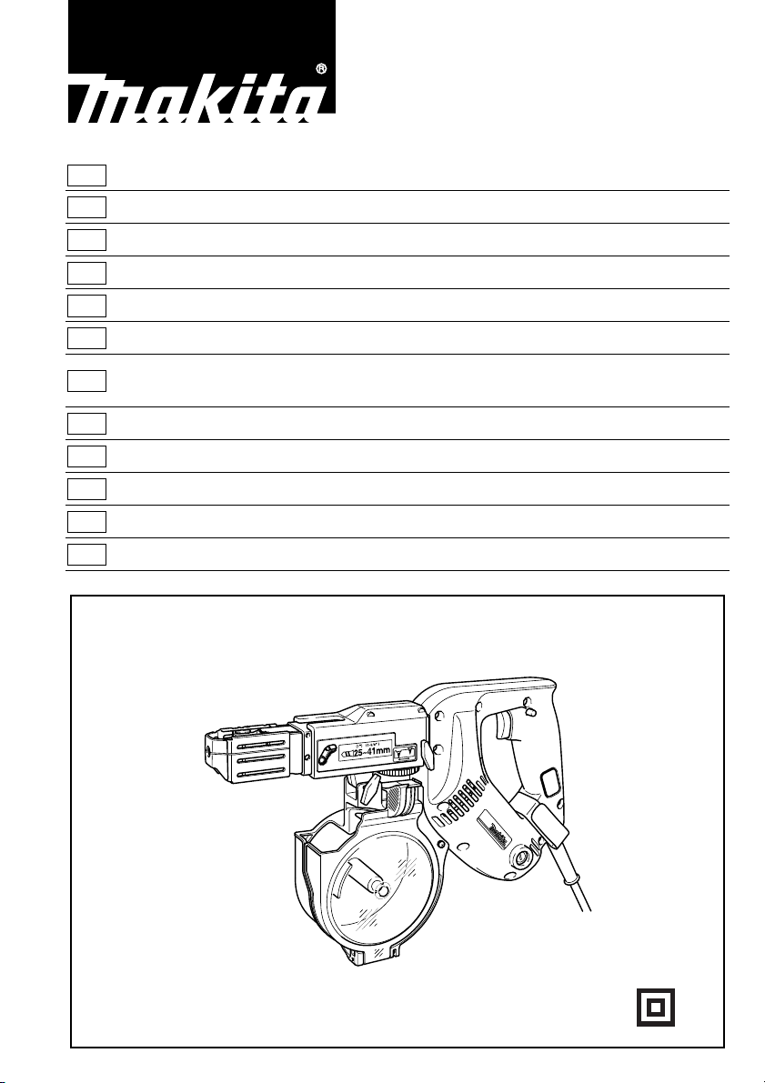
GB Auto Feed Screwdriver
F
Visseuse à recharge automatique Manuel d’instructions
D
Magazin-Schnellbauschrauber Betriebsanleitung
I
Avvitatore ad auto-alimentazione Istruzioni per l’uso
NL
Schroef automaat Gebruiksaanwijzing
E
Atornillador autoalimentado Manual de instrucciones
Chave de parafusos com alimentação
P
automática
DK
Magasin Skrueautomat Brugsanvisning
S
Skruvdragare med automatisk matning Bruksanvisning
N
Skrutrekker med automatisk tilførsel Bruksanvisning
SF
Makasiini-pikaruuvinväännin Käyttöohje
GR Γεµιστήρας ταχυβιδωτήρας Οδηγίες χρήσεως
Instruction Manual
Manual de instruções
6837
Page 2
1
2
3
12
4
6
5
7
8
34
5 mm
9
10
11
4
4
B
A
10
12
56
13
15
14
16
78
2
Page 3
17
13
14
910
18
19
11 12
13 14
21
15 16
20
3
Page 4
10
15 mm
17 18
23
24
19
22
4
Page 5

Symbols
The followings show the symbols used for the tool. Be sure that you understand their meaning before use.
Symboles
Nous donnons ci-dessous les symboles utilisés pour l’outil. Assur ez-vous que vous en avez bien compris la sign ification avant d’utiliser l’outil.
Symbole
Die folgenden Symbole werden für die Ma schine verwendet . Machen Sie si ch vor der Benutzun g unbeding t mit ihrer
Bedeutung vertraut.
Symboli
Per questo utensile vengono usati i simboli seguenti. Bisogna capire il loro significato prima di usare l’utensile.
Symbolen
Voor dit gereedschap worden de volgende symb olen gebruikt. Zorg e rvoor dat u de betekenis van deze symbolen
begrijpt alvorens het gereedschap te gebruiken.
Símbolos
A continuación se muestran los símbolos utilizados con esta herramien ta. Asegúrese d e que entien de su significado
antes de usarla.
Símbolos
O seguinte mostra os símbolos utilizados para a ferramenta. Certifique-se de que compreende o seu significado antes
da utilização.
Symboler
Nedenstående symbole r e r a nvendt i forbind else me d d enne maskine. Vær sikker på, a t D e ha r forståe t sym bo lernes
betydning, før maskinen anvendes.
Symboler
Det följande visar de symb oler som används för den här maskinen. Se noga till att du förstår dera s innebörd innan
maskinen används.
Symbolene
Følgende viser de symblene som brukes for maskinen . Det er viktig å forstå bet ydningen av disse før maskinen tas i
bruk.
Symbolit
Alla on esitetty koneessa käytetyt symbolit. Opettele näiden merkitys, ennen kuin käytät konetta.
Σύµβολα
Τα ακλουθα δείχνουν τα σύµβολα που χρησιµοποιούνται για το µηχάνηµα. Βεβαιωθείτε τι καταλαβαίνετε
τη σηµασία τους πριν απ τη χρήση.
❏ Read instruction manual.
❏ Lire le mode d’emploi.
❏ Bitte Betriebsanleitung lesen.
❏ Leggete il manuale di istruzioni.
❏ Lees de gebruiksaanwijzing.
❏ Lea el manual de instrucciones.
❏ DOUBLE INSULATION
❏ DOUBLE ISOLATION
❏ DOPPELT SCHUTZISOLIERT
❏ DOPPIO ISOLAMENTO
❏ DUBBELE ISOLATIE
❏ DOBLE AISLAMIENTO
❏ Leia o manual de instruções.
❏ Læs brugsanvisningen.
❏ Läs bruksanvisningen.
❏ Les bruksanvisingen.
❏ Katso käyttöohjeita.
❏ ∆ιαβάστε τις οδηγίες χρήσης
❏ DUPLO ISOLAMENTO
❏ DOBBELT ISOLATION
❏ DUBBEL ISOLERING
❏ DOBBEL ISOLERING
❏ KAKSINKERTAINEN ERISTYS
❏ ∆ΙΠΛΗ ΜΟΝΩΣΗ
5
Page 6
ENGLISH
1 Lock button
2 Switch trigger
3Hook
4Casing
5 T hu mb screws
6Bit
7Dust cover
8 Plain bearing
Explanation of general view
9Lever
10 Stopper base
11 Plate
12 Adjusting knob
13 Lock lever
14 Magazine cap
15 Screw strip
16 Magazine
17 Slotted passage
18 Portion A
19 Screw-driving position
20 Reverse button
21 Extension handle
22 Li mit mark
23 Screwdriver
24 Brus h holder cap
SPECIFICATIONS
Model 6837
Screw strip ................................ 4 mm x 25 mm – 40 mm
No load speed (min
Overall length ..................................................... 364 mm
Net weight ............................................................. 2.1 kg
Safety class........................................... ..... ..... ..... ... /II
• Due to our conti nuing program of rese arch and development, the specifications herein are subject to change
without notice.
• Note: Specifications may differ from country to country.
Intended use
The tool is int end ed for scr ew d r ivi ng in wood, metal and
plastic.
Power supply
The tool should be connected o nly to a power s upply of
the same voltage as indicated on the nameplate, and can
only be operated on sing le-phase AC supply. They are
double-insulated in accor dance with E uropean Stand ard
and can, therefore, also be us ed from sockets without
earth wire.
Safety hints
For your own safety, please refer to the en closed safety
instructions.
–1
) ............................... ............. 6,000
SPECIFIC SAF E TY RULES
DO NOT let comfort or familiarity with product
GEB017-1
(gained from repeated use) replace strict
adherence to screwdriver safety rules. If you use
this tool unsafely or incorrectly, you can suffer
serious personal injury.
1. Hold power tools by insulated grip ping surfaces
when performing an operation where the cutting
tool may contact hidden wiring or its own cord.
Contact with a “live” wire will make exposed metal
parts of the tool “live” and shock the operator.
2. Always be sure you have a firm foot ing. Be sure
no one is below when using the tool in high locations.
3. Hold the tool firmly.
4. Keep hands away from rotating parts.
5. Do not touch th e bit or the workpiece immedi-
ately after operati on; they may be extremely hot
and could bu r n your skin.
SAVE THESE INSTRUCTIONS.
WARNING:
MISUSE or failure to follow the safety rules stat ed
in this instruction manual may cause seri ous
personal injury.
FUNCTIONAL DESCRIPTION
CAUTION:
• Always be sure that the tool is switched off and
unplugged before adjusting or checking function on the
tool.
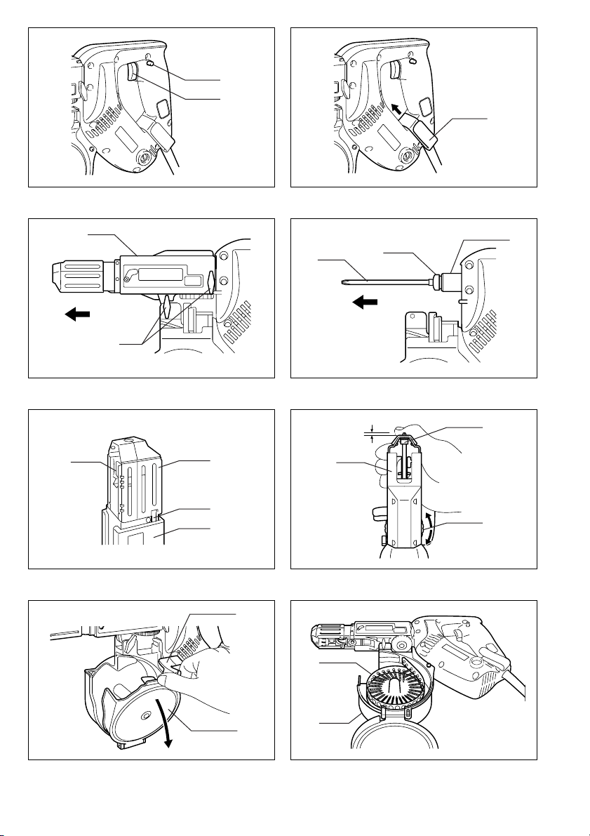
Switch action ( Fig. 1)
CAUTION:
• Before plugging in the tool, always check to see that
the switch trigger ac tuates proper ly and return s to the
“OFF” position when released.
To start the tool, simply pul l the trigge r. Release the trigger to stop.
For continuous operation, pull the trigger and the n push
in the lock button.
To stop the tool from the locked position, pull the switch
trigger fully, then release it.
Hook (Fig. 2)
The hook is convenient for hooking the tool to your belt. It
can be installed on either side of the tool. To remove it,
pull it out in the direction of the arrow while raising. To
install the hook, push it down un ti l it “cl icks” into pl a ce on
the tool.
ASSEMBLY
CAUTION:
• Always be sure that the tool is switched off and
unplugged before carrying out any work on the tool.
Installing or removing bit
Loosen the thumb screws which secure the casing. Pull
out the casing in the direction of the arrow. (Fig. 3)
Press the dust cover toward the plain be aring and pull
out the bit. If the dust cover cannot be moved as far as
the plain bearing, try it again after turning the bit slightly.
To install the bit, insert it into the socket while turning it
slightly. After installing, always make sure that the bit is
securely held in place by trying to pull it out. (Fig. 4)
6
Page 7

Setting for desired screw length (Fig. 5)
There are 3 positive-lock screw length settings. To obtain
the desired setting, pull out the stopper base while
depressing the lever until you see the number of the
desired screw length (indi cated on the plate) appear to
rest on the very top edge of the casing. See the table
below for the relation b etween the number indicated on
the plate and the respective screw length ranges.
Number indicated
on the plate
25/28 25 – 28
32 28 – 35
40 35 – 41
Adjusting the driving depth (Fig. 6)
Depress the stopper base as far as it will go. While keeping it in this position, turn the adjusting knob until the bit
tip projects approx. 5 mm from the stopp er base. Dr ive a
trial screw. If the screw head projects a bove the surface
of the workpiece, turn the ad justing k nob in the “A ” dir ection; if the screw head is countersun k, tur n the adjus ting
knob in the “B” direction.
Screw length range
(mm)
Installing screw st rip
1. Squeeze the lock lever with fingers and open the
magazine cap. (Fig. 7)
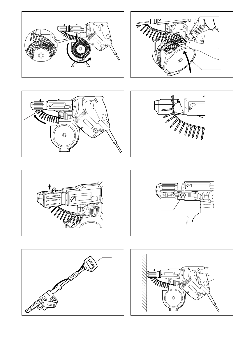
2. Roll up the screw strip in a form of coil counterclockwise and place it inside the magazine. (Fig. 8)
3. Run the end of the screw str ip on the slotted passage starting from above the magazine. (Fig. 9)
4. Close the magazine ca p while squeezing the lock
lever with fingers. (Fig.10)
5. Insert the t op end o f the screw s trip into the por ti on
A of the feeder box and feed it in the direction of the
arrow. (Fig. 11)
6. Set the screw strip so that the first screw of the strip
seats with a space for one screw left before the
screw-driving position. (Fig. 12)
Removing the screw strip
When removing the screw s trip at or b efore usin g up the
screws, pull it out in the direction of the arrow. (Fig. 13)
If you depress the reverse button, you can pull out the
screw strip in the reverse direction of the arrow. (Fig. 14)
Extension handle (optional accessory) (Fig. 15)
Use of extension handle allows you to drive screws into
floors while standing.
OPERATION
Driving operation (Fig. 16)
Switch on the tool by pressing the trigger and at the
same time pushing the lock button. Hold the tool squarely
against the workpiece a nd apply forward press ure to the
tool. The screw will be automatically carried to the driving
position and driven into the workpiece.
NOTE:
• Do not fire the tool without screws. This will damage
the workpiece.
• If the feeder box becomes sluggish in operatio n, spray
car wax (spray type wax) on its sliding surfaces. Never
lubricate it.
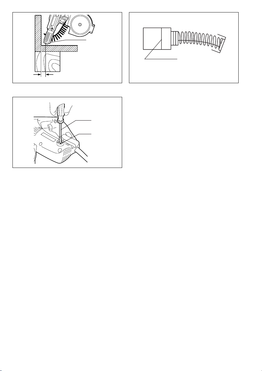
Driving in corner (Fig. 17)
This tool can be used to drive at a position 15 mm away
from the w all as shown in Fig. 17.
CAUTION:
Driving at a position closer than 15 mm to the wall or driving with the stopper base in contact with the wall may
damage the screw heads and cause wear on the bit. This
may also lead to poor fastening of screws and malfu nction of the tool.
MAINTENANCE
CAUTION:
• Always be sure that the tool is switched off and
unplugged before atte mpting to perform ins pection or
maintenance.
Replacing carbon brushes (Fig. 18 & 19)
Remove and check the carbon brushes regularly.
Replace when they wear down to the limit mark. Keep
the carbon brus hes clean a nd free to slip in th e holders.
Both carbon brushes should be replaced at the same
time. Use only identical carbon brushes.
Use a screwdriver t o remove the brush ho lder caps. Take
out the worn ca rbon brushes, inser t the new ones and
secure the brush holder caps.
To maintain product SAFETY and RELIABILITY, repairs,
any other maintenance or adjustment should be performed by Makita Authorized Service Centers, always
using Makita replacement parts.
ACCESSORIES
CAUTION:
• These accessories or attachments are recommend ed
for use with your Makita tool specifie d in this manual.
The use of any other accessories or attachments might
present a risk of injur y t o persons. O nly use acce ssor y
or attachm ent for its stated purpose.
If you need any assistance for more details regarding
these accessories, ask your local Makita service center.
• Phillips bit
• Drywall screw strips
• Extension handle
• Plastic carrying case
7
Page 8

NEDERLANDS
1 Vergrendelknop
2 Trekschakelaar
3Haak
4 Behuizing
5 Vleugelschroeven
6Bit
7 Stofkap
8 Lager
Verklaring van algemene gegevens
9 Hendel
10 Stopvoet
11 Plaat
12 Regelknop
13 Sluithendel
14 Magazijndeksel
15 Schroefstrip
16 Magazijn
17 Gesleufde doorgang
18 Gedeelte A
19 Inschroefpositie
20 Omkeerknop
21 Verlenghandgreep
22 Limietmarkering
23 Schroevendraaier
24 Borstelhouderkap
TECHNISCHE GEGEVENS
Model 6837
Schroefstrip .............................. 4 mm x 25 mm – 40 mm
Toerental onbelast (min
Totale lengte .......................................................364 mm
Netto gewicht ......................................................... 2,1 kg
Veiligheidsklasse..................................................... /II
• In verband met ononderb roken research en ontwikkeling behouden wij ons het recht voor bovenstaande
technische gegevens te wijzigen zonder voorafgaande
kennisgeving.
• Opmerking: De technisch e gegevens kunnen van land
tot land verschillen.
Doeleinden van gebruik
Dit gereedschap is bedoeld voor het indraaien van
schroeven in hout, metaal en kunststof.
Stroomvoorziening
De machine mag alleen worden aangesloten op een
stroombron van hetzelfde voltag e als aang egeven op de
naamplaat, en kan alleen op enkel-fase wisselstroom
worden gebruikt. De machine is dubbel-geïsoleerd volgens de Europese standaard en kan derhalve ook op
een niet- geaard stopkontakt worden aangesloten.
Veiligheidswenken
Voor uw veiligheid dient u de bijgevoegde Veiligheidsvoorschriften nauwkeurig op te volgen.
-1
) ......................................6 000
BIJGEVOEGDE VEILIGHEIDSVOORSCHRIFTEN
VOOR HET GEREEDSCHAP
Laat u NIET misleiden door een vals gevoel van
comfort en bekendheid met het g ereedschap (na
veelvuldig gebruik) en neem alle
veiligheidsvoorschriften van de schroefmachine
altijd strikt in acht.
1. Houd elektrisch gereedschap vast aan het geïso-
leerde oppervlak van de ha ndgrepen wanne er u
werkt op plaatse n waar het snijg er eed sch ap met
verborgen bedrading of zijn eigen snoer in aanraking kan komen.
Door contact met on der spanning staande drad en,
zullen de niet-geïsoleerde metalen delen van het
gereedschap onder sp anning komen te staan zo dat
de gebruiker een elektrische schok kan krijgen.
2. Zorg er altijd voor da t u stevige steun voor de
voeten hebt. Zorg ervoor dat niemand zich onder
het gereedschap bevindt wanneer u dit op hoge
plaatsen gebruikt.
3. Houd het gereedschap goed vast.
4. Houd uw handen uit de buurt van draaiende
onderdelen.
5. Raak onmiddellijk na het inschroeven de bit niet
aan, aangezien d eze ontzet tend heet ka n zijn en
brandwonden kan veroorzaken.
BEWAAR DEZE V OORSCHRIFTEN.
WAARSCHUWING:
VERKEERD GEBRUIK of het niet naleven van de
veiligheidsvoorschriften in deze
gebruiksaanwijzing kan leiden tot ernstige
persoonlijke verwonding.
BESCHRIJVING V AN DE FUNCTIES
LET OP:
• Zorg altijd dat het gereedschap is uitgeschakeld en niet
op een stopcontact is aan gesloten voordat u functies
op het gereedschap instelt of controleert.
Werking van de trekschakelaar (Fig. 1)
LET OP:
• Alvorens de stekker van het gereedschap in het stop-
contact te steken, moet u altijd controle ren of de trekschakelaar goed werkt en b ij loslaten naar de “OFF”
stand terugkeert.
Om het gereedschap in te schakelen, dr ukt u de trekschakelaar gewoon in. Laat de trekschakelaar lo s om te
stoppen.
Voor continuë werking, de trekschakelaar indrukken en
dan de vergrendelknop indrukken.
Om het gereedschap vanuit deze vergrendeld e stand te
doen stoppen, de trekschakelaar helema al indrukken en
dan loslaten.
Haak (Fig. 2)
De haak is nuttig om het gereed scha p aa n uw br oekriem
vast te haken. De haak kan aan een van beide zijden van
het gereedschap word en aangebracht. Om de haak te
verwijderen, breng de haak omhoog en trek hem eruit in
de richting van het pijltje. Om de haak aan te brengen,
druk hem naar bened en totdat hij vastklikt op zijn plaats
op het gereedschap.
INEENZETTEN
LET OP:
• Zorg altijd dat het gereedschap is uitgeschakeld en niet
op een stopcontact is aan gesloten alvorens enig wer k
aan het gereedschap uit te voeren.
15
Page 9

Installeren of verwijderen van de bit
Draai de vleugelschro even los waarmee de behu izing is
bevestigd. Verwijder de behuizing in de r ichting van het
pijltje. (Fig. 3)
Duw de stofkap in de r ich ting van h et la ge r e n tr ek d e b it
eruit. Wanneer de stofkap niet tot te gen het lager kan
worden geduwd, verdraai de bit dan een beetje e n probeer opnieuw.
Om de bit te installeren, steekt u hem in de houder terwijl
u hem lichtjes draait. Controleer na het in stalleren altijd
of de bit goed vastzit door eraan te trekken. (Fig. 4)
Instellen van de gewenste schroeflengte (Fig. 5)
Er zijn 3 schroeflengte-instellingen beschikbaar. Om de
gewenste instelling te krijge n, trekt u de stopvoet naar
buiten terwijl u de hendel naar beneden drukt totdat het
getal van de gewenste schro eflengte (aangeduid op de
plaat) net boven de bovenrand van d e behu izing komt te
staan. Raadpleeg de onderstaande tabel voor de verhouding tussen de getallen aangeduid op de plaat en de
overeenkomstige schroeflengten.
Getal aangeduid
op de plaat
25/28 25 – 28
32 28 – 35
40 35 – 41
Schroeflengtebereik
(mm)
Instellen van d e schroefdiepte (F i g . 6)
Druk de stopvoet zo ver mogelijk in. Houd hem in deze
positie en draai de regelknop tot de bitpunt ongeveer
5 mm uit de stopvoet steekt. Draai een testschroef in.
Indien de schroefkop boven het opper vlak van het werkstuk uitsteekt, moet u de regelknop in de “A” richting
draaien; indien de sc hroefkop verzonken zit, moet u de
regelknop in de “B” richting draaien.
De schroefstrip installeren
1. Druk de sluithe ndel met uw vingers i n en open het
magazijndeksel. (Fig. 7)
2. Rol de schroefstr ip linksom op in de vorm van een
spoel en plaats hem in het magazijn. (Fig. 8)
3. Haal het uiteinde van de schroefstr ip doorheen de
gesleufde doorga ng, beginnend vanaf de b ovenkan t
van het magazijn. (Fig. 9)
4. Druk de sluithendel met uw ving er s in om het ma gazijndeksel te sluiten. (Fig. 10)
5. Steek het boveneinde van de schroefstrip in het
gedeelte A van de toevoerbox en schuif h et in de
richting van het pijltje. (Fig. 11)
6. Plaats de schroefstrip zodanig dat er één-schroef
vrije ruimte is tussen de eerste schroef van de
schroefstrip en de inschroefpositie. (Fig. 12)
De schroefstrip verwijderen
Om de schroefstrip te verwijderen voordat of nadat alle
schroeven zijn opgebruikt, trek t u hem in de r ichting van
het pijltje eruit. (Fig. 13)
Als u de omkeerknop indrukt, kunt u de schroefstrip in de
tegenovergestelde richting van het pijltje eruit trekken.
(Fig. 14)
Verlenghandgreep
(los verkrijgbaar acc esso ire) (Fig. 15)
Door de verleng handgreep te gebrui ken kunt u schroeven in vloeren indrijven terwijl u rechtop staat.
BEDIENING
Bediening voor inschroeven (Fig. 16)
Schakel het gereedschap in door de treksch akelaar en
de vergrendelknop tegelijkertijd in te drukken. Houd het
gereedschap recht tegen he t werkstuk en dr uk het naar
voren. De schroef wordt automa tisch naar de inschr oefpositie gebracht en in het werkstuk gedraaid.
OPMERKING:
• Laat het gereeds chap niet werken zonder schroeven
erin. Daardoor zal het werkstuk namelijk bescha digd
worden.
• Wanneer de toevoerbox niet meer soepel werkt, spuit
dan autoboenwas (spuittype was) op zijn glijvlakken.
Nooit smeren.
Schroeven in hoeken (Fig. 17)
Dit gereedschap kan word en gebruikt voor inschroeven
op minimaal 15 mm van de muur vandaan, zoals afgebeeld in Fig. 17.
LET OP:
Indien u inschroeft o p een pl aats die m inder dan 15 mm
van de muur is verwijderd, of inschroeft terwijl de stopvoet de muur raakt, kunnen de schroefkoppen beschadigd raken en zal de bit rapper verslijten. Bovendien
zullen de schroeven dan mogelijk niet goed vastgezet
zijn en kan het gereedschap defect raken.
ONDERHOUD
LET OP:
• Zorg altijd dat het gereedschap is uitgeschakeld en niet
op een stopcontact is aangesloten voordat u begint met
inspectie of onderhoud.
Vervangen van de koolborstels (Fig. 18 en 19)
Verwijder en controleer regelmatig de koolborstels. Vervang de koolborstels wanneer ze tot aan de limietmarkering versleten zijn. Houd de koolborstels schoon zodat ze
goed in de houders glijden. Beide koolborstels dienen
tegelijkertijd te worden vervangen. Gebruik uitsluitend
identieke koolborstels.
Gebruik een schroevendraaier om de doppen van de
koolborstelhouders te verwijderen. Haal de versleten borstels eruit, steek de nieuwe erin, en zet de doppen weer
goed vast.
Om de VEILIGH EID en BETROUWBAARHEID van he t
product te handhaven, dienen alle reparaties en alle
andere onderhoudswerkzaamheden of afstellingen te
worden uitgevoerd door een erkend Makita Ser vicecentrum, en dat uits luitend met gebrui k van Makita vervangingsonderdelen.
16
Page 10

ACCESSORES
LET OP:
• Deze accessoires of hulpstukken worden aanbevolen
voor gebruik met het Ma kita gereedschap dat in de ze
gebruiksaanwijzing wordt beschreven. Het gebruik van
andere accessoires of hulpstukken kan gevaar voor
persoonlijke verwonding opl everen. Gebruik de accessoires of hulpstukken uitsluitend voor het gespecificeerde doel.
Wenst u meer informatie over deze acc essoires, neem
dan contact op met het dich tstbijzijnde Makita servicecentrum.
• Phillips bit
• Schroefstrip met schroeven voor gestapelde muren
• Verlenghandgreep
• Plastic draagkoffer
17
Page 11

ENGLISH
EC-DECLARATION OF CONFORMITY
We declare under our sole responsibility that this product
is in compliance with the following standards of standardized documents,
in accordance with Council Directives, 89/336/EEC and
98/37/EC.
EN60745, EN55014, EN61000
ENH101-5
ITALIANO
DICHIARAZIONE DI CONFORMITÀ
CON LE NORME DELLA COMUNITÀ EUROPEA
Dichiariamo sotto la nostra sola responsabilità che
questo prodotto è conforme agli standard di d ocumenti
standardizzati seguenti:
secondo le direttive del Consiglio 89/336/CEE e 98/37/CE.
EN60745, EN55014, EN61000
FRANÇAISE
DÉCLARATION DE CONFORMITÉ CE
Nous déclarons sous notre entière responsabilité que ce
produit est conforme aux normes des documents st andardisés suivants,
conformément aux Direct ives du Conseil, 8 9/336/ CEE e t
98/37/EG.
EN60745, EN55014, EN61000
DEUTSCH
CE-KONFORMITÄTSERKLÄRUNG
Hiermit erklärt wir unter unserer alleinigen Verantwortung, daß dieses Produkt gemäß den Ratsdirektiven
89/336/EWG und 98 /37/EG mit den folgenden Norm en
von Normendokumenten übereinstimmen:
EN60745, EN55014, EN61000.
Yasuhiko Kanzaki
NEDERLANDS
EG-VERKLARING VAN CONFORMITEIT
Wij verklaren hierbij uitsluitend op eigen verantwoordelijkheid da t dit produkt voldoet aan de volgende
normen van genormaliseerde documenten,
in overeenstemming met de richtlijnen van de Raad
89/336/EE C en 98/37/EC.
EN60745, EN55014, EN61000
ESPAÑOL
DECLARACIÓN DE CONFORMIDAD DE LA CE
Declaramos bajo nuestra sola respon sabilidad que este
producto cumple con las siguientes normas de documentos normalizados,
de acuerdo con las directivas comunitarias,
89/336/EEC y 98/37/CE.
CE 2005
EN60745, EN55014, EN61000
34
Director Amministratore
Directeur Directeur
Direktor Director
MAKITA INTERNATIONAL EUROPE LTD.
Michigan Drive, Tongwell, Milton Keynes,
Bucks MK15 8JD, ENGLAND
Responsible manufacturer: Produttore responsabile:
Fabricant responsable
Verantwortlicher Hersteller: Fabricante responsable:
Makita Corporation Anjo Aichi Japan
: Verantwoordelijke fabrikant:
Page 12

PORTUGUÊS
DECLARAÇÃO DE CONFORMIDADE DA CE
Declaramos sob inteira responsabilidade que este
produto obedece às seg uintes normas de documentos
normalizados,
de acordo com as directivas 89/336/CE E e 98/37/CE do
Conselho.
EN60745, EN55014, EN61000
ENH101-5
NORSK
EUs SAMSVARS-ERKLÆRING
Vi
erklærer på
ensstemmelse med følgende standard i de standardiserte dokumenter:
i samsvar med Råds-direktivene, 89/336/EEC og
98/37/EC.
eget ansvar at det te produktet er i over-
EN60745, EN55014, EN61000,
DANSK
EU-DEKLARATION OM KONFORMITET
Vi erklære r hermed på eg et ansvar, at dette prod ukt er i
overensstemmelse med de følgende standarder i de normsættende dokumenter,
i overensstemmelse med Rådets Di rektiver 89/336/EEC
og 98/37/EC.
EN60745, EN55014, EN61000
SVENSKA
EG-DEKLARATION OM ÖVERENSSTÄMMELSE
Under eget ansvar deklarerar vi härmed att denna
produkt överensstämmer m ed fö lj and e stan da rdis e r ing ar
för standardiserade dokument,
i enlighet med EG-direktiven 89/336/EEC och 98/37/EC.
EN60745, EN55014, EN61000
Yasuhiko Kanzaki
SUOMI
VAKUUTUS EC-VASTAAVUUDESTA
Yksinomaisesti vastuullisina ilmoitamme, että tämä tuote
on seuraavien standardoitujen dokumenttien standardien mukainen,
neuvoston direktiivien 89/336/EEC ja 98/37/EC mukaisesti.
EN60745, EN55014, EN61000
ΕΛΛΗΝΙΚΑ
∆ΗΛΩΣΗ ΣΥΜΜΟΡΦΩΣΗΣ ΕΚ
∆ηλώνουµε υπ την µοναδική µας ευθύνη τι αυτ
το προιν βρίσκεται σε Συµφωνία µε τα ακλουθα
πρτυπα τυποποιηµένων εγγράφων,
σύµφωνα µε τις Οδηγίες του Συµβουλίου,
89/336/EEC και 98/37/ΚE.
CE 2005
EN60745, EN55014, EN61000
Director Direktor
Direktør Johtaja
Direktör ∆ιευθυντής
MAKITA INTERNATIONAL EUROPE LTD.
Michigan Drive, Tongwell, Milton Keynes,
Bucks MK15 8JD, ENGLAND
Fabricante responsável: Ansvarlig produsent :
Ansvarlig fabrikant: Vastaava valmistaja:
Ansvarig tillverkare: Υπεύθυνος κατασκευαστής:
Makita Corporation Anjo Aichi Japan
35
Page 13

ENGLISH
For European countries only
The typical A-weighted sound pressure level is 83 dB (A).
Uncertainty is 3 dB (A).
The noise level under working may exceed 85 dB (A).
The typical weighted root mean square acceleration
value is not more than 2.5 m/s
These values have been obtained according to
EN60745.
Noise and Vibration
– Wear ear protection. –
2
.
ENG003-2-V2
ITALIANO
Modello per l’Europa soltanto
Il livello di pressione sonora pesata secondo la curva A è
di 83 dB (A).
L’incertezza è di 3 dB (A).
Il livello di rumor e dura nte il lavoro potrebbe superar e gli
85 dB (A).
Il valore quadratico medio d i accel lerazione n on s upera i
2
2,5 m/s
Questi valori sono stati ottenuti in conformità EN60745.
Rumore e vibrazi one
– Indossare i paraorecchi. –
.
FRANÇAISE
Pour les pays d’Europe uniquement
Bruit et vib rations
Le niveau de pression sonore pondere type A est de
83 dB (A).
L’incertitude de mesure est de 3 dB (A).
Le niveau de bruit en fonctionnement peut dépasser
85 dB (A).
L’accélération pondérée ne dépasse pas 2,5 m/s
– Porter des protecteurs anti-bruit. –
2
.
Ces valeurs ont été obtenues selon EN60745.
DEUTSCH
Nur für europäische Länder
Geräusch- und Vi br at i on se nt w icklu ng
Der typische A-bewertete Schalldruckpegel beträgt
83 dB (A).
Die Abweichung beträgt 3 dB (A).
Der Lärmpegel kann während des Betriebs 85 dB (A)
überschreiten.
Der gewichtete Effektivwert der Beschleunigung beträgt
nicht mehr als 2,5 m/s
Diese Werte wurden gemäß EN60745 erhalten.
– Gehörschutz tragen. –
2
.
NEDERLANDS
Alleen voor Europese landen
Het typische A-gewogen geluidsdrukniveau is 83 dB (A).
Geluidsniveau en trilling
Onzekerheid is 3 dB (A).
Tijdens het werken kan het geluidsniveau 85 dB (A) overschrijden.
De typische gewogen effectieve versnellingswaarde is
niet meer da n 2,5 m/s
Deze waarden werden verkregen in overeenstemming
– Draag oorbeschermers. –
2
.
met EN60745.
ESPAÑOL
Para países europeos solamente
El nivel de presión sonora ponderada A es de 83 dB (A).
Incerteza 3 dB (A).
El nivel de ruido en condiciones de trabajo puede que
sobrepase los 85 dB (A).
El valor ponderado de la acel eración no sobrepasa los
2
.
2,5 m/s
Estos valores han sido obtenidos de acuerdo con
EN60745.
Ruido y vibración
– Póngase protectores en los oídos. –
36
Page 14

PORTUGUÊS
Só para países Europeus
O nível normal de pressão sonora A é 83 dB (A).
A incerteza é de 3 dB (A).
O nível de ruído durante o trabalho pode exceder
85 dB (A).
– Utilize protectores para os ouvidos –
O valor médio da aceleração é inferior a 2,5 m/s
Estes valores foram obtidos de acordo com EN60745.
Ruído e vibração
2
.
ENG003-2-V2
NORSK
Gjelder bare land i Europa
Det vanlige A-verktet lydtrykksnivå er 83 dB (A).
Usikkerheten er på 3 dB (A).
Under bruk kan støynivået overskride 85 dB (A).
Den typiske vektede effektive akselerasjonsverdi overskrider ikke 2,5m/s
Disse verdiene er beregnet eller målt i samsvar med
EN60745.
Støy og vibrasjon
– Benytt hørselvern. –
2
.
DANSK
Kun for lande i Europa
Lyd og vibration
Det typiske A-vægtede lydtryksniveau er 83 dB (A).
Der er en usikkerhed på 3 dB (A).
Støjniveauet under arbejde kan overstige 85 dB (A).
– Bær høreværn. –
Den vægtede effektive accelerationsværdi overstiger ikke
2
.
2,5m/s
Disse værdier er beregnet i overensstemmelse med
EN60745.
SVENSKA
Endast för Europa
Den typiska-A-vägda ljudtrycks nivån är 83 dB (A).
Osäkerheten är 3 dB (A).
Bullernivån under pågående arbete kan överstiga
85 dB (A).
Det typiskt vägda effektivvärdet för accelerati on överstiger inte 2,5 m/s
Dessa värden har erhållits i enlighet med EN60745.
Buller och vibration
– Använd hörselskydd –
2
.
SUOMI
Vain Euroopan maat
Melutaso ja tärinä
Tyypillinen A-painotettu äänenpainetaso on 83 dB (A).
Epävarmuus on 3 dB (A).
Melutaso työpaikalla saattaa ylittää 85 dB (A).
– Käytä kuulosuojaimia. –
Tyypillinen kiihtyvyyden painotettu tehollisarvo ei ylitä
2
.
2,5m/s
Nämä arvot on mitattu normin EN60745 mukaisesti.
ΕΛΛΗΝΙΚΑ
Μ,νο για χώρες της Ευρώπης
Η τυπική Α-µετρούµενη ηχητική πίεση είναι
83 dB (A).
Η Αβεβαιτητα είναι 3 dB (A).
Η ένταση ήχου υπο συνθήκες εργασίας µπορεί να
µπερβεί τα 85 dB (A).
Η τυπική αξία της µετρούµενης ρίζας του µέσου
τετραγώνου της επιτάχυνσης δεν ξεπερνά τα
2,5 m/s
Αυτές οι τιµές έχουν σηµειωθεί σύµφωνα µε το
ΕΝ60745.
Θ,ρυβος και κραδασµ,ς
– Φοράτε ωτοασπίδες. –
2
.
37
Page 15

38
Page 16

39
Page 17

Makita Corporation
Anjo, Aichi, Japan
884517A996
 Loading...