

Makita 6835D User Manual
GB
Cordless Auto Feed Screwdriver Instruction Manual
F
Visseuse automatique sans fil Manuel d’instructions
D
Akku-Schnellbau-Magazin-Schrauber
I
Avvitatore autoalimentato a batteria
NL
Accu schroefautomaat Gebruiksaanwijzing
E
Atornillador autoalimentado a batería
Chave de parafusos com alimentação
P
automática a bateria
Akku skruemaskine med automatisk
DK
skrueforsyning
Sladdlös skruvdragare med automatisk
S
matning
Batteridrevet automatisk matende
N
skrutrekker
SF
Akkukäyttöinen makasiini-ruuvinväännin
GR
Γεµιστήρας ταχυβιδωτήρας µε µπαταρία
Betriebsanleitung
Istruzioni per l’uso
Manual de instrucciones
Manual de instruções
Brugsanvisning
Bruksanvisning
Bruksanvisning
Käyttöohje
Οδηγίες χρήσεως
6835D
1
3
2
4
5
6
12
7
4
6
8
B
A
9
10
11
34
12
56
13
14
78
2
15
910
16
4
15 mm
11 12
20
19
18
13
6
17
3

ENGLISH
1 Push button
2 Battery car tridge
3Lever
4 Stopper base
5Plate
6 Casing
7Approx. 5mm
Explanation of general view
8 Adjusting knob
9 Feeder box
10 Screw strip
11 Screw guide
12 Driving position
13 Reverse button
14 Hook
15 Switch trigger
16 Wall
17 Thumb screws
18 Bit
19 Dust cover
20 Plain bearing
SPECIFICATIONS
Model 6835D
Screw strip ............................. 4 mm x 25 mm – 41 mm
No load speed (min
Overall length .....................................................364 mm
Net weight (with battery cartridge) ........................ 2.0 kg
Rated voltage .................................................... D.C.12 V
• Due to our continuing program of research and development, the specifications herein are subject to change
without notice.
• Note: Specifications may differ from country to country.
Intended use
The tool is intended for screw driving in wood, metal and
plastic.
Safety hints
For your own safety, please refer to the enclosed safety
instructions.
-1
) ............................................ 2,000
IMPORTANT SAFETY INSTRUCTIONS FOR
CHARGER & BATTERY CARTRIDGE
1. Before using battery cartridge, read all instruc-
tions and cautionary markings on (1) battery
charger, (2) battery, and (3) product using battery.
2. Do not disassemble battery cartridge.
3. If operating time has become excessively
shorter, stop operating immediately. It may
result in a risk of overheating, possible burns
and even an explosion.
4. If electrolyte gets into your eyes, rinse them out
with clear water and seek medical attention right
away. It may result in loss of your eyesight.
5. Always cover the battery terminals with the bat-
tery cover when the battery cartridge is not
used.
6. Do not short the battery cartridge:
(1) Do not touch the terminals with any conduc-
tive material.
(2) Avoid storing battery cartridge in a container
with other metal objects such as nails, coins,
etc.
(3) Do not expose battery cartridge to water or
rain.
A battery short can cause a large current flow,
overheating, possible burns and even a breakdown.
ENC004-1
7. Do not store the tool and battery cartridge in
locations where the temperature may reach or
exceed 50°C (122°F).
8. Do not incinerate the battery cartridge even if it
is severely damaged or is completely worn out.
The battery cartridge can explode in a fire.
9. Be careful not to drop or strike battery.
SAVE THESE INSTRUCTIONS.
Tips for maintaining maximum battery life
1. Charge the battery cartridge before completely
discharged.
Always stop tool operation and charge the battery cartridge when you notice less tool power.
2. Never recharge a fully charged battery cartridge.
Overcharging shortens the battery service life.
3. Charge the battery cartridge with room temperature at 10°C – 40°C (50°F – 104°F). Let a hot battery cartridge cool down before charging it.
4. Charge the Nickel Metal Hydride battery cartridge when you do not use it for more than six
months.
SPECIFIC SAFETY RULES
DO NOT let comfort or familiarity with product
GEB017-1
(gained from repeated use) replace strict
adherence to screwdriver safety rules. If you use
this tool unsafely or incorrectly, you can suffer
serious personal injury.
1. Hold power tools by insulated gripping surfaces
when performing an operation where the cutting
tool may contact hidden wiring or its own cord.
Contact with a “live” wire will make exposed metal
parts of the tool “live” and shock the operator.
2. Always be sure you have a firm footing. Be sure
no one is below when using the tool in high locations.
3. Hold the tool firmly.
4. Keep hands away from rotating parts.
5. Do not touch the bit or the workpiece immediately after operation; they may be extremely hot
and could burn your skin.
SAVE THESE INSTRUCTIONS.
WARNING:
MISUSE or failure to follow the safety rules stated in
this instruction manual may cause serious personal
injury.
4

OPERATING INSTRUCTIONS
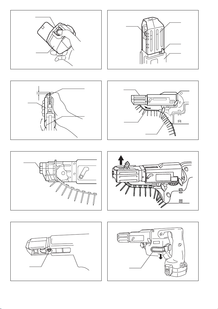
Installing or removing battery cartridge (Fig. 1)
• Always switch off the tool before insertion or removal of
the battery cartridge.
• To remove the battery cartridge, withdraw it from the
tool while pressing the push buttons on both sides of
the cartridge.
• To insert the battery car tridge, align the tongue on the
battery cartridge with the groove in the housing and slip
it into place. Always insert it all the way until it locks in
place with a little click. If not, it may accidentally fall out
of the tool, causing injury to you or someone around
you.
• Do not use force when inserting the battery cartridge. If
the cartridge does not slide in easily, it is not being
inserted correctly.
Setting for desired screw length (Fig. 2)
There are 3 positive-lock screw length settings. To obtain
the desired setting, pull out the stopper base while
depressing the lever until you see the number of the
desired screw length (indicated on the plate) appear to
rest on the very top edge of the casing. See the table
below for the relation between the number indicated on
the plate and the respective screw length ranges.
Number indicated
on the plate
25/28 25 – 28
32 28 – 5
40 35 – 41
Adjusting the driving depth (Fig. 3)
Depress the stopper base as far as it will go. While keeping it in this position, turn the adjusting knob until the bit
tip projects approx. 5 mm from the stopper base. Drive a
trial screw. If the screw head projects above the driving
surface, turn the adjusting knob in the A direction; if the
screw head is countersunk, turn the adjusting knob in the
B direction.
Installing screw strip (Fig. 4 & 5)
Insert the screw strip through the screw guide. Then
insert it through the feeder box until the first screw
reaches the position next to the driving position.
Removing screw strip (Fig. 6 & 7)
To remove the screw strip, just pull it out in the direction
of the arrow. If you depress the reverse button, you can
pull out the screw strip in the reverse direction of the
arrow.
Carry hook (Fig. 8)
The carry hook is convenient for temporarily hooking the
tool. It can be installed on either side of the tool. When
installing or removing the carry hook, widen it by pressing
its lower portion in the direction of the arrow.
Screw length range
(mm)
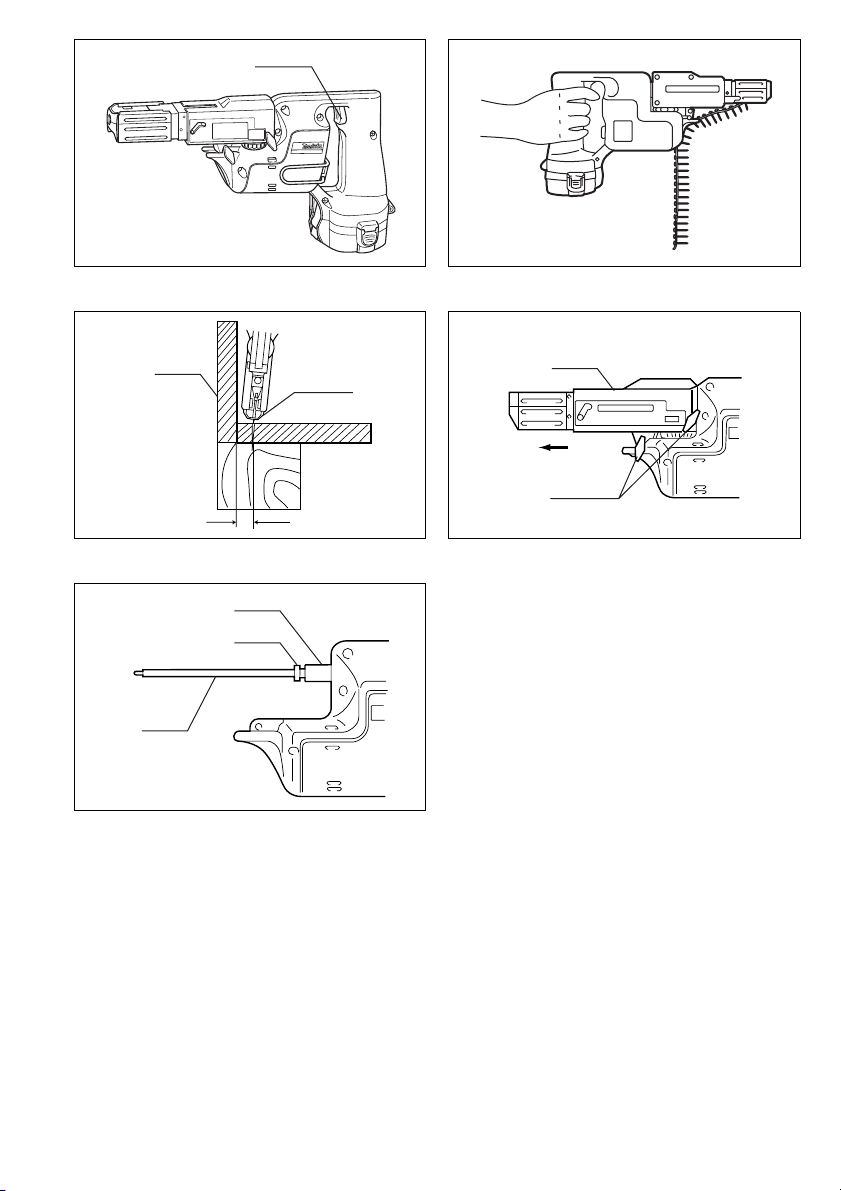
Switch action (Fig. 9)
CAUTION:
Before inserting the battery cartridge into the tool, always
check to see that the switch trigger actuates properly and
returns to the “OFF” position when released.
To start the tool, simply pull the trigger. Release the trigger to stop.
Driving operation (Fig. 10)
Switch on the tool by pulling the switch trigger. Hold the
tool squarely and firmly up against the driving surface. A
screw will be automatically carried to the driving position
and fastened.
CAUTION:
• Always check the bit carefully for wear before driving
operations. Replace a worn bit or poor fastening may
result.
• Always hold the tool squarely against the driving surface. Holding it at an angle may damage the screw
heads and cause wear on the bit. This may also lead to
poor fastening.
• Always keep the tool firmly against the driving surface
until the driving is over. Failure to do so may cause
insufficient fastening of screws.
• Be careful not to drive a screw onto another screw
already fastened.
• Do not operate the tool without screws. It will damage
the driving surface.
• If the feeder box does not work smoothly when driving
screws, spray car wax (spray type) on the sliding surfaces. Never lubricate it.
Driving in corner (Fig. 11)
This tool can be used to drive at a position 15 mm away
from the wall as shown in Fig. 11.
CAUTION:
Driving at a position closer than 15 mm to the wall or
driving with the stopper base in contact with the wall may
damage the screw heads and cause wear on the bit. This
may also lead to poor fastening of screws and malfunction of the tool.
Installing or removing bit (Fig. 12 & 13)
Important:
Always be sure that the tool is switched off and the battery cartridge is removed before installing or removing
the bit.
Loosen the thumb screws which secure the casing. Pull
out the casing in the direction of the arrow. Press the dust
cover toward the plain bearing and pull out the bit. If the
dust cover cannot be moved as far as the plain bearing,
try it again after turning the bit slightly. To install the bit,
insert it into the socket while turning it slightly. After
installing, always make sure that the bit is securely held
in place by trying to pull it out.
5
 Loading...