

INSTRUCTION MANUAL
MANUEL D'INSTRUCTION
MANUAL DE INSTRUCCIONES
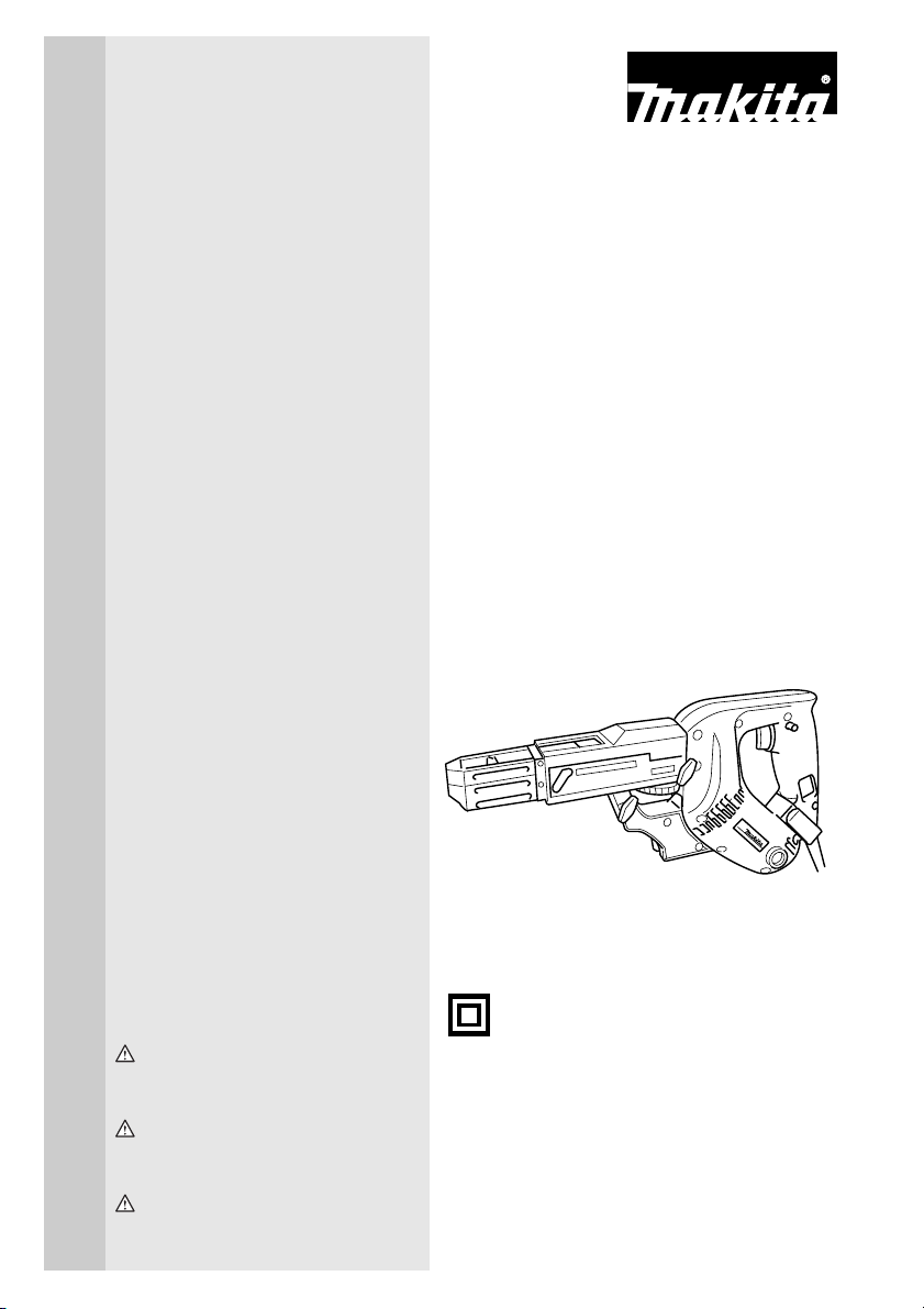
Auto Feed Screwdriver
Visseuse à recharge automatique
Atornillador
6833
6834
002607
DOUBLE INSULATION
DOUBLE ISOLATION
DOBLE AISLAMIENTO
WARNING:
For your personal safety, READ and UNDERSTAND before using.
SAVE THESE INSTRUCTIONS FOR FUTURE REFERENCE.
AVERTISSEMENT:
Pour votre propre sécurité, prière de lire attentivement avant l’utilisation.
GARDER CES INSTRUCTIONS POUR RÉFÉRENCE ULTÉRIEURE.
ADVERTENCIA:
Para su seguridad personal, LEA DETENIDAMENTE este manual antes de usar la herramienta.
GUARDE ESTAS INSTRUCCIONES PARA FUTURA REFERENCIA.

ENGLISH
SPECIFICATIONS
Model 6833 6834
Screw strip 4 mm x 25 mm - 41 mm (5/32” x 1” - 1-5/8”) 4 mm x 25 mm - 57 mm (5/32” x 1” - 2-1/4”)
No load speed (RPM) 4,700/min. 2,800/min.
Overall length 364 mm (14-3/8”) 396 mm (15-5/8”)
Net weight 1.9 kg (4.2 lbs) 1.9 kg (4.2 lbs)
• Due to our continuing programme of research and development, the specifications herein are subject to change
without notice.
• Note: Specifications may differ from country to country.
GENERAL SAFETY RULES
USA002-2
(For All Tools)
WARNING:
Read and understand all instructions.
Failure to follow all instructions listed below,
may result in electric shock, fire and/or serious personal injury.
SAVE THESE INSTRUCTIONS
Work Area
1. Keep your work area clean and well lit. Cluttered
benches and dark areas invite accidents.
2. Do not operate power tools in explosive atmo-
spheres, such as in the presence of flammable
liquids, gases, or dust. Power tools create sparks
which may ignite the dust or fumes.
3. Keep bystanders, children, and visitors away
while operating a power tool. Distractions can
cause you to lose control.
Electrical Safety
4. Double insulated tools are equipped with a
polarized plug (one blade is wider than the
other.) This plug will fit in a polarized outlet only
one way. If the plug does not fit fully in the outlet,
reverse the plug. If it still does not fit, contact a
qualified electrician to install a polarized outlet.
Do not change the plug in any way. Double insula-
tion eliminates the need for the three wire
grounded power cord and grounded power supply
system.
5. Avoid body contact with grounded surfaces
such as pipes, radiators, ranges and refrigerators. There is an increased risk of electric shock if
your body is grounded.
6. Do not expose power tools to rain or wet conditions. Water entering a power tool will increase the
risk of electric shock.
7. Do not abuse the cord. Never use the cord to
carry the tools or pull the plug from an outlet.
Keep cord away from heat, oil, sharp edges or
moving parts. Replace damaged cords immediately. Damaged cords increase the risk of electric
shock.
8. When operating a power tool outside, use an
outdoor extension cord marked “W-A” or “W”.
These cords are rated for outdoor use and reduce
the risk of electric shock.
Personal Safety
9. Stay alert, watch what you are doing and use
common sense when operating a power tool. Do
not use tool while tired or under the influence of
drugs, alcohol, or medication. A moment of inat-
tention while operating power tools may result in
serious personal injury.
10. Dress properly. Do not wear loose clothing or
jewelry. Contain long hair. Keep your hair, clothing, and gloves away from moving parts. Loose
clothes, jewelry, or long hair can be caught in moving parts.
11. Avoid accidental starting. Be sure switch is off
before plugging in. Carrying tools with your finger
on the switch or plugging in tools that have the
switch on invites accidents.
12. Remove adjusting keys or wrenches before turning the tool on. A wrench or a key that is left
attached to a rotating part of the tool may result in
personal injury.
13. Do not overreach. Keep proper footing and balance at all times. Proper footing and balance
enables better control of the tool in unexpected situations.
14. Use safety equipment. Always wear eye protection. Dust mask, non-skid safety shoes, hard hat, or
hearing protection must be used for appropriate conditions. Ordinary eye or sun glasses are NOT eye
protection.
2

Tool Use and Care
15. Use clamps or other practical way to secure and
support the workpiece to a stable platform. Hold-
ing the work by hand or against your body is unstable and may lead to loss of control.
16. Do not force tool. Use the correct tool for your
application. The correct tool will do the job better
and safer at the rate for which it is designed.
17. Do not use tool if switch does not turn it on or
off. Any tool that cannot be controlled with the
switch is dangerous and must be repaired.
18. Disconnect the plug from the power source
before making any adjustments, changing
accessories, or storing the tool. Such preventive
safety measures reduce the risk of starting the tool
accidentally.
19. Store idle tools out of reach of children and
other untrained persons. Tools are dangerous in
the hands of untrained users.
20. Maintain tools with care. Keep cutting tools
sharp and clean. Properly maintained tools with
sharp cutting edges are less likely to bind and are
easier to control.
21. Check for misalignment or binding of moving
parts, breakage of parts, and any other condition
that may affect the tools operation. If damaged,
have the tool serviced before using. Many acci-
dents are caused by poorly maintained tools.
22. Use only accessories that are recommended by
the manufacturer for your model. Accessories
that may be suitable for one tool, may become hazardous when used on another tool.
SERVICE
23. Tool service must be performed only by qualified
repair personnel. Service or maintenance per-
formed by unqualified personnel could result in a risk
of injury.
24. When servicing a tool, use only identical
replacement parts. Follow instructions in the
Maintenance section of this manual. Use of unau-
thorized parts or failure to follow Maintenance
instructions may create a risk of electric shock or
injury.
USE PROPER EXTENSION CORD: Make sure your
extension cord is in good condition. When using an
extension cord, be sure to use one heavy enough to
carry the current your product will draw. An undersized
cord will cause a drop in line voltage resulting in loss of
power and overheating. Table 1 shows the correct size to
use depending on cord length and nameplate ampere
rating. If in doubt, use the next heavier gage. The smaller
the gage number, the heavier the cord.
Table 1. Minimum gage for cord
Ampere Rating
Volts Total length of cord in feet
120 V 25 ft. 50 ft. 100 ft. 150 ft.
More Than Not More Than AWG
0 6 18 16 16 14
6 10 18161412
10 12 16 16 14 12
12 16 14 12 Not Recommended
SPECIFIC SAFETY RULES
USB004-2
DO NOT let comfort or familiarity with
product (gained from repeated use)
replace strict adherence to screwdriver
safety rules. If you use this tool unsafely
or incorrectly, you can suffer serious personal injury.
1. Hold tool by insulated gripping surfaces when
performing an operation where the cutting tool
may contact hidden wiring or its own cord. Con-
tact with a “live” wire will make exposed metal parts
of the tool “live” and shock the operator.
2. Always be sure you have a firm footing.
Be sure no one is below when using the tool in
high locations.
3. Hold the tool firmly.
4. Keep hands away from rotating parts.
5. Do not touch the bit or the workpiece immediately after operation: they may be extremely hot
and could burn your skin.
SAVE THESE INSTRUCTIONS
WARNING:
MISUSE or failure to follow the safety
rules stated in this instruction manual
may cause serious personal injury.
3
SYMBOLS
The followings show the symbols used for tool.
V............................volts
A ...........................amperes
Hz..........................hertz
....................alternating current
.......................no load speed
.......................Class II Construction
.../min....................revolutions or reciprocation per
minute
USD201-2
FUNCTIONAL DESCRIPTION
CAUTION:
• Always be sure that the tool is switched off and
unplugged before adjusting or checking function on
the tool.
Switch action
002629
1
2
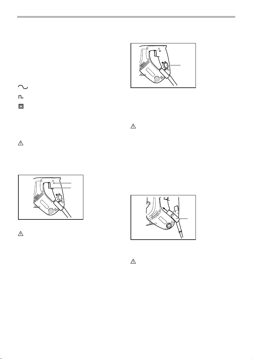
1. Lock button
2. Switch trigger
Reversing switch action
This tool has a reversing switch to change the direction of
rotation. Press the upper side (FWD side) of the reversing switch for clockwise rotation or the lower side (REV
side) of the reversing switch for counterclockwise rotation.
CAUTION:
• Always check the direction of rotation before opera-
tion.
• Use the reversing switch only after the tool comes
to a complete stop. Changing the direction of rotation before the tool stops may damage the tool.
002636
1. Reversing
switch
1
Hook
The hook is convenient for hooking the tool to your belt. It
can be installed on either side of the tool. To remove it,
pull it out in the direction of the arrow while raising. To
install the hook, push it down until it “clicks” into place on
the tool.
002648
1. Hook
CAUTION:
• Before plugging in the tool, always check to see
that the switch trigger actuates properly and returns
to the “OFF” position when released.
To start the tool, simply pull the switch trigger. Release
the switch trigger to stop.
For continuous operation, pull the switch trigger and then
push in the lock button.
To stop the tool from the locked position, pull the switch
trigger fully, then release it.
1
ASSEMBLY
CAUTION:
• Always be sure that the tool is switched off and
unplugged before carrying out any work on the tool.
4
Installing or removing the bit
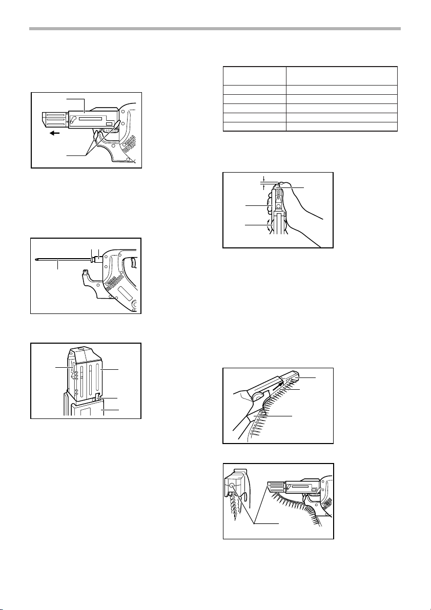
Loosen the thumb screws which secure the casing. Pull
out the casing in the direction of the arrow.
1
2
Press the dust cover toward the plain bearing and pull
out the bit. If the dust cover cannot be moved as far as
the plain bearing, try it again after turning the bit slightly.
To install the bit, insert it into the socket while turning it
slightly. After installing, always make sure that the bit is
securely held in place by trying to pull it out.
12
3
Setting for desired screw length
1
002656
002657
002663
2
3
4
1. Casing
2. Thumb screw
1. Dust cover
2. Plane bearing
3. Bit
1. Lever
2. Stopper base
3. Plate
4. Casing
Number indicated
Screw length range
002664
on the plate
25/28
32
40
* 51
* 57
25 mm (1”) - 28 mm (1 - 1/8")
28 mm (1 - 1/8”) - 35 mm (1 - 3/8”)
35 mm (1 - 3/8”) - 41 mm (1 - 5/8”)
41 mm (1 - 5/8”) - 51 mm (2”)
51 mm (2”) - 57 mm (2 - 1/4”)
(Note) * for Model 6834 only
Adjusting the driving depth
5mm (3/16")
002665
1. Stopper plate
1
2. Casing
3. Adjusting knob
2
B
3
A
Depress the stopper base as far as it will go. While keeping it in this position, turn the adjusting knob until the bit
tip projects approx. 5 mm (3/16”) from the stopper base.
Drive a trial screw. If the screw head projects above the
surface of the workpiece, turn the adjusting knob in the A
direction; if the screw head is counter-sunk, turn the
adjusting knob in the B direction.
Installing screw strip
Insert the screw strip through the screw guide. Then
insert it through the feeder box until the first screw
reaches the position next to the driving position.
002666
1. Feeder box
1
2
2. Screw strip
3. Screw guide
3
There are 3 (for Model 6833) or 5 (for Model 6834) positive-lock screw length settings. To obtain the desired setting, pull out the stopper base while depressing the lever
until you see the number of the desired screw length
(indicated on the plate) appear to rest on the very top
edge of the casing. See the table below for the relation
between the number indicated on the plate and the
respective screw length ranges.
002667
1. Driving position
1
5
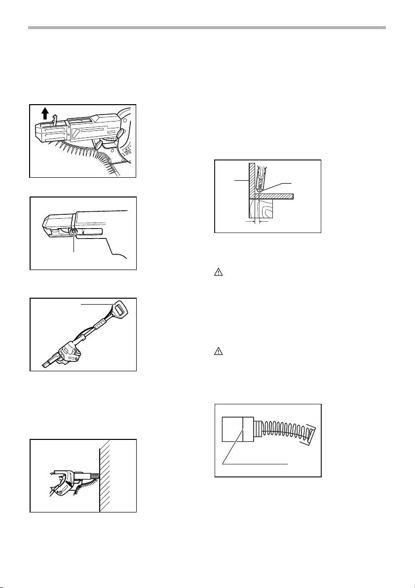
Removing screw strip
To remove the screw strip, just pull it out in the direction
of the arrow. If you depress the reverse button, you can
pull out the screw strip in the reverse direction of the
arrow.
002668
002669
1. Reverse button
squarely against the workpiece and apply forward pressure to the tool. The screw will be automatically carried to
the driving position and driven into the workpiece.
NOTE:
• Do not fire the tool without screws. This will dam-
age the workpiece.
• If the feeder box becomes sluggish in operation,
spray car wax (spray type wax) on its sliding surfaces. Never lubricate it.
Driving in corner
1
15mm(5/8”)
001887
1. Wall
2. Stopper base
2
1
Extension handle (optional accessory)
1
Use of extension handle allows you to drive screws into
floors while standing.
002671
1. Extension handle
OPERATION
Driving operation
Switch on the tool by pressing the switch trigger and at
the same time pushing the lock button. Hold the tool
002676
This tool can be used to drive at a position 15 mm (5/8”)
away from the wall as shown in the figure.
CAUTION:
• Driving at a position closer than 15 mm (5/8”) to the
wall or driving with the stopper base in contact with
the wall may damage the screw heads and cause
wear on the bit. This may also lead to poor fastening of screws and malfunction of the tool.
MAINTENANCE
CAUTION:
• Always be sure that the tool is switched off and
unplugged before attempting to perform inspection
or maintenance.
Replacing carbon brushes
Remove and check the carbon brushes regularly.
Replace when they wear down to the limit mark. Keep
the carbon brushes clean and free to slip in the holders.
Both carbon brushes should be replaced at the same
time. Use only identical carbon brushes.
001145
1. Limit mark
1
6

Use a screwdriver to remove the brush holder caps. Take
out the worn carbon brushes, insert the new ones and
secure the brush holder caps.
To maintain product SAFETY and RELIABILITY, repairs,
any other maintenance or adjustment should be performed by Makita Authorized or Factory Service Centers,
always using Makita replacement parts.
002686
1. Screwdriver
2. Brush holder
cap
1
2
ACCESSORIES
CAUTION:
• These accessories or attachments are recom-
mended for use with your Makita tool specified in
this manual. The use of any other accessories or
attachments might present a risk of injury to persons. Only use accessory or attachment for its
stated purpose.
If you need any assistance for more details regarding
these accessories, ask your local Makita Service Center.
• Phillips bit
• Extension handle
• Plastic carrying case
MAKITA LIMITED ONE YEAR WARRANTY
Warranty Policy
Every Makita tool is thoroughly inspected and tested
before leaving the factory. It is warranted to be free of
defects from workmanship and materials for the period of
ONE YEAR from the date of original purchase. Should
any trouble develop during this one year period, return
the COMPLETE tool, freight prepaid, to one of Makita’s
Factory or Authorized Service Centers. If inspection
shows the trouble is caused by defective workmanship or
material, Makita will repair (or at our option, replace)
without charge.
This Warranty does not apply where:
• repairs have been made or attempted by others:
• repairs are required because of normal wear and
tear:
• the tool has been abused, misused or improperly
maintained:
• alterations have been made to the tool.
IN NO EVENT SHALL MAKITA BE LIABLE FOR ANY
INDIRECT, INCIDENTAL OR CONSEQUENTIAL DAMAGES FROM THE SALE OR USE OF THE PRODUCT.
EN0006-1
THIS DISCLAIMER APPLIES BOTH DURING AND
AFTER THE TERM OF THIS WARRANTY.
MAKITA DISCLAIMS LIABILITY FOR ANY IMPLIED
WARRANTIES, INCLUDING IMPLIED WARRANTIES
OF “MERCHANTABILITY” AND “FITNESS FOR A SPECIFIC PURPOSE,” AFTER THE ONE YEAR TERM OF
THIS WARRANTY.
This Warranty gives you specific legal rights, and you
may also have other rights which vary from state to state.
Some states do not allow the exclusion or limitation of
incidental or consequential damages, so the above limitation or exclusion may not apply to you. Some states do
not allow limitation on how long an implied warranty lasts,
so the above limitation may not apply to you.
7

FRANÇAIS
SPÉCIFICATIONS
Modèle 6833 6834
Bande porte-vis 4 mm x 25 mm - 41 mm (5/32” x 1” - 1-5/8”) 4 mm x 25 mm - 57 mm (5/32” x 1” - 2-1/4”)
Vitesse à vide (T/MIN) 4,700/min. 2,800/min.
Longueur totale 364 mm (14-3/8”) 396 mm (15-5/8”)
Poids net 1.9 kg (4.2 lbs) 1.9 kg (4.2 lbs)
• Le fabricant se réserve le droit de modifier sans avertissement les spécifications.
• Note: Les spécifications peuvent varier selon les pays.
RÈGLES DE SÉCURITÉ
GÉNÉRALES
USA002-2
(Pour tous les outils)
AVERTISSEMENT:
Vous devez lire et comprendre toutes les
instructions. Le non-respect, même partiel,
des instructions ci-après entraîne un risque
de choc électrique, d’incendie et/ou de
blessures graves.
CONSERVEZ CES
INSTRUCTIONS
Aire de travail
1. Veillez à ce que l’aire de travail soit propre et
bien éclairée. Le désordre et le manque de lumière
favorisent les accidents.
2. N’utilisez pas d’outils électriques dans une
atmosphère explosive, par exemple en présence
de liquides, de gaz ou de poussières
inflammables. Les outils électriques créent des
étincelles qui pourraient enflammer les poussières
ou les vapeurs.
3. Tenez à distance les curieux, les enfants et les
visiteurs pendant que vous travaillez avec un
outil électrique. lls pourraient vous distraire et vous
faire une fausse manoeuvre.
Sécurité électrique
4. Les outils à double isolation sont équipés d’une
fiche polarisée (une des lames est plus large que
l’autre), qui ne peut se brancher que d'une seule
façon dans une prise polarisée. Si la fiche
n’entre pas parfaitement dans la prise, inversez
sa position ; si elle n’entre toujours pas bien,
demandez à un électricien qualifié d’installer une
prise de courant polarisée. Ne modifiez pas la
fiche de l’outil. La double isolation élimine le
besoin d’un cordon d’alimentation à trois fils avec
mise à la terre ainsi que d’une prise de courant mise
à la terre.
5. Évitez tout contact corporel avec des surfaces
mises à la terre (tuyauterie, radiateurs,
cuisinières, réfrigérateurs, etc.). Le risque de
choc électrique est plus grand si votre corps est en
contact avec la terre.
6. N’exposez pas les outils électriques à la pluie ou
à l’eau. La présence d’eau dans un outil électrique
augmente le risque de choc électrique.
7. Ne maltraitez pas le cordon. Ne transportez pas
l’outil par son cordon et ne débranchez pas la
fiche en tirant sur le cordon. N’exposez pas le
cordon à la chaleur, à des huiles, à des arêtes
vives ou à des pièces en mouvement.
Remplacez immédiatement un cordon
endommagé. Un cordon endommagé augmente le
risque de choc électrique.
8. Lorsque vous utilisez un outil électrique à
l’extérieur, employez un prolongateur pour
l’extérieur marqué “W-A” ou “W”. Ces cordons
sont faits pour être utilisés à l’extérieur et réduisent
le risque de choc électrique.
Sécurité des personnes
9. Restez alerte, concentrez-vous sur votre travail
et faites preuve de jugement. N’utilisez pas un
outil électrique si vous êtes fatigué ou sous
l'influence de drogues, d’alcool ou de
médicaments. Un instant d’inattention suffit pour
entraîner des blessures graves.
10. Habillez-vous convenablement. Ne portez ni
vêtements flottants ni bijoux. Confinez les
cheveux longs. N’approchez jamais les
cheveux, les vêtements ou les gants des pièces
en mouvement. Des vêtements flottants, des bijoux
ou des cheveux longs risquent d’être happés par
des pièces en mouvement.
11. Méfiez-vous d’un démarrage accidentel. Avant
de brancher l’outil, assurez-vous que son
interrupteur est sur ARRÊT. Le fait de transporter
8

un outil avec le doigt sur la détente ou de brancher
un outil dont l’interrupteur est en position MARCHE
peut mener tout droit à un accident.
12. Enlevez les clés de réglage ou de serrage avant
de démarrer l’outil. Une clé laissée dans une pièce
tournante de l’outil peut provoquer des blessures.
13. Ne vous penchez pas trop en avant. Maintenez
un bon appui et restez en équilibre en tout
temps. Un bonne stabilité vous permet de mieux
réagir à une situation inattendue.
14. Utilisez des accessoires de sécurité. Portez
toujours des lunettes ou une visière. Selon les
conditions, portez aussi un masque antipoussière,
des bottes de sécurité antidérapantes, un casque
protecteur et/ou un appareil antibruit. Les lunettes
ordinaires et les lunettes de soleil NE constituent
PAS des lunettes de protection.
Utilisation et entretien des outils
15. Immobilisez le matériau sur une surface stable
au moyen de brides ou de toute autre façon
adéquate. Le fait de tenir la pièce avec la main ou
contre votre corps offre une stabilité insuffisante et
peut amener un dérapage de l’outil.
16. Ne forcez pas l’outil. Utilisez l’outil approprié à
la tâche. L’outil correct fonctionne mieux et de façon
plus sécuritaire. Respectez aussi la vitesse de
travail qui lui est propre.
17. N’utilisez pas un outil si son interrupteur est
bloqué. Un outil que vous ne pouvez pas
commander par son interrupteur est dangereux et
doit être réparé.
18. Débranchez la fiche de l’outil avant d’effectuer
un réglage, de changer d’accessoire ou de
ranger l’outil. De telles mesures préventives de
sécurité réduisent le risque de démarrage accidentel
de l’outil.
19. Rangez les outils hors de la portée des enfants
et d’autres personnes inexpérimentées. Les
outils sont dangereux dans les mains d’utilisateurs
novices.
20. Prenez soin de bien entretenir les outils. Les
outils de coupe doivent être toujours bien
affûtés et propres. Des outils bien entretenus, dont
les arêtes sont bien tranchantes, sont moins
susceptibles de coincer et plus faciles à diriger.
21. Soyez attentif à tout désalignement ou
coincement des pièces en mouvement, à tout
bris ou à toute autre condition préjudiciable au
bon fonctionnement de l’outil. Si vous constatez
qu’un outil est endommagé, faites-le réparer
avant de vous en servir. De nombreux accidents
sont causés par des outils en mauvais état.
22. N’utilisez que des accessoires que le fabricant
recommande pour votre modèle d’outil. Certains
accessoires peuvent convenir à un outil, mais être
dangereux avec un autre.
RÉPARATION
23. La réparation des outils électriques doit être
confiée à un réparateur qualifié. L’entretien ou la
réparation d’un outil électrique par un amateur peut
avoir des conséquences graves.
24. Pour la réparation d’un outil, n’employez que
des pièces de rechange d’origine. Suivez les
directives données à la section «ENTRETIEN» de
ce manuel. L’emploi de pièces non autorisées ou le
non-respect des instructions d’entretien peut créer
un risque de choc électrique ou de blessures.
UTLISEZ UN CORDON PROLONGATEUR ADÉQUAT:
Assurez-vous que le cordon prolongateur est en bon
état. Lors de l’utilisation d’un cordon prolongateur,
utilisez sans faute un cordon assez gros pour conduire le
courant que le produit nécessite. Un cordon trop petit
provoquera une baisse de tension de secteur, résultant
en une perte de puissance et une surchauffe. Le Tableau
1 indique la dimension appropriée de cordon selon sa
longueur et selon l’intensité nominale indiquée sur la
plaque signalétique. En cas de doute sur un cordon
donné, utilisez le cordon suivant (plus gros). Plus le
numéro de gabarit indiqué est petit, plus le cordon est
gros.
Tableau 1. Gabarit minimum du cordon
Intensité nominale
Volts Longueur totale du cordon en pieds
120 V 25 pi 50 pi 100 pi 150 pi
Plus de Pas plus de Calibre américain des fils
0 6 18 16 16 14
6 10 18161412
10 12 16 16 14 12
12 16 14 12 Non recommandé
9

RÈGLES DE SÉCURITÉ
PARTICULIÈRES
USB004-2
NE vous laissez PAS tromper (au fil d’une
utilisation répétée) par un sentiment
d’aisance et de familiarité avec le
produit, en négligeant le respect
rigoureux des consignes de sécurité qui
accompagnent la visseuse. L’utilisation
non sécuritaire ou incorrecte de cet outil
comporte un risque de blessure grave.
1. Tenez l’outil par ses surfaces de prise isolées
pendant toute opération où l’outil de coupe
pourrait venir en contact avec un câblage
dissimulé ou avec son propre cordon. En cas de
contact avec un conducteur sous tension, les pièces
métalliques à découvert de l’outil transmettraient un
choc électrique à l’utilisateur.
2. Veillez à garder toujours une bonne assise.
Assurez-vous que personne ne se trouve audessous de vous quand vous utilisez l’outil en
situation élevée.
3. Tenez votre outil fermement.
4. Gardez les mains éloignées des pièces en
mouvement.
5. Ne touchez ni l’embout ni sa pièce
immédiatement après un vissage. Ils peuvent
être extrêmement chauds et risquer de vous
brûler.
CONSERVEZ CE MODE
D’EMPLOI
AVERTISSEMENT:
La MAUVAISE UTILISATION de l’outil ou
l’ignorance des consignes de sécurité
indiquées dans ce manuel d’instructions
peut entraîner une blessure grave.
.......................vitesse à vide
.......................construction, catégorie II
.../min ...................tours ou alternances par minute
DESCRIPTION DU
FONCTIONNEMENT
ATTENTION:
• Assurez-vous toujours que l’outil est hors tension et
débranché avant de l’ajuster ou de vérifier son
fonctionnement.
Interrupteur
ATTENTION:
• Avant de brancher l’outil, assurez-vous toujours
que la gâchette fonctionne correctement et revient
en position d’arrêt une fois relâchée.
Pour faire démarrer l’outil, appuyez simplement sur la
gâchette. Pour l’arrêter, relâchez la gâchette.
Pour une utilisation continue, tirez sur la gâchette et
appuyez sur le bouton de verrouillage.
Pour arrêter l’outil alors qu’il est en position verrouillée,
tirez à fond sur la gâchette puis relâchez-la.
Inverseur
1
2
1
002629
1. Bouton de
verrouillage
2. Gâchette
002636
1. Inverseur
SYMBOLES
USD201-2
Les symboles utilisés pour l’outil sont présentés cidessous.
V............................volts
A ...........................ampères
Hz..........................hertz
....................courant alternatif
L’outil possède un inverseur qui permet d’intervertir le
sens de rotation. Appuyez sur la face supérieure (côté
FWD) de l’inverseur pour une rotation dans le sens des
aiguilles d’une montre, ou sur la face inférieure (côté
REV) pour une rotation en sens inverse.
10

ATTENTION:
• Vérifiez toujours le sens de rotation avant de mettre
l’outil en marche.
• N’actionnez l’inverseur qu’une fois que l’outil est
complètement arrêté. Si vous changez le sens de
rotation avant l’arrêt de l’outil, vous risquez de
l’endommager.
Crochet
L’outil est équipé d’un crochet pratique pour l’accrocher à
la ceinture. Il s’installe d’un côté comme de l’autre de
l’outil. Pour le retirer, tirez-le dans le sens de la flèche
tout en le soulevant. Pour mettre le crochet en place,
enfoncez-le jusqu’à ce qu’il se mette en place en
émettant un bruit sec.
002648
1. Crochet
1
ASSEMBLAGE
ATTENTION:
• Avant d’effectuer toute intervention sur l’outil,
assurez-vous toujours qu’il est hors tension et
débranché.
Installation et retrait du foret
Desserrez les vis à ailettes qui retiennent le bâti.
Dégagez le bâti en le tirant dans le sens de la flèche.
1
002656
1. Bâti
2. Vis à oreilles
002657
12
1. Capuchon
anti-poussière
2. Support plat
3
Réglage pour la longueur de vis désirée
3. Embout
002663
1. Levier
2. Base de butée
1
3. Plaque
2
4. Bâti
3
4
3 (modèle 6833) ou 5 (modèle 6834) réglages de
longueur de vis sont disponibles, avec verrouillage à
enclenchement. Pour effectuer le réglage désiré, tirez sur
la base de butée pour la retirer tout en appuyant sur le
levier jusqu’à ce que le chiffre indiquant la longueur de
vis désirée (indiquée sur la plaque) se trouve
complètement sur le bord supérieur du bâti. Consultez le
tableau ci-dessous pour connaître la relation entre les
chiffres indiqués sur la plaque et les longueurs de vis
respectives.
Chiffre indiqué
Plage de longueur de vis
002664
sur la plaque
25/28
32
40
* 51
* 57
25 mm (1”) - 28 mm (1-1/8”)
28 mm (1-1/8”) - 35 mm (1-3/8”)
35 mm (1-3/8”) - 41 mm (1-5/8”)
41 mm (1-5/8”) - 51 mm (2”)
51 mm (2”) - 57 mm (2-1/4”)
(Note) * Pour Modèle 6834 seulement
2
Poussez le capuchon anti-poussière vers le palier lisse et
tirez sur l’embout pour le dégager. Si vous n’arrivez pas à
déplacer le capuchon anti-poussière jusqu’au palier
lisse, réessayez après avoir tourné légèrement l’embout.
Pour installer l’embout, insérez-le dans la douille tout en
le faisant légèrement tourner. Après l’installation, tirez
sur l’embout pour vous assurer qu’il est solidement
maintenu en place.
Réglage de la profondeur de vissage
5mm (3/16")
002665
1
2
B
3
A
11
1. Plaque de butée
2. Bâti
3. Bouton de
réglage

Enfoncez la base de butée le plus possible. Tout en la
maintenant dans cette position, tournez le bouton de
réglage jusqu’à ce que l’extrémité de l’embout dépasse
d’environ 5 mm (3/16”) par rapport à la base de butée.
Enfoncez une vis d’essai. Si la tête de vis dépasse de la
surface de la pièce, tournez le bouton de réglage dans le
sens A ; si elle s’enfonce sous la surface de la pièce,
tournez le bouton de réglage dans le sens B.
Installation de la bande porte-vis
Insérez la bande porte-vis par le guide de vis. Insérez-le
ensuite par la boîte d’alimentation, jusqu’à ce que la
première vis se trouve en position adjacente à la position
de vissage.
002666
1. Boîte
1
2
d’alimentation
2. Bande porte-vis
3. Guide de vis
3
002669
1. Bouton
inverseur
1
Poignée de rallonge (accessoire en option)
1
002671
1. Poignée de
rallonge
002667
1. Position de
vissage
1
Retrait de la bande porte-vis
Pour retirer la bande porte-vis, tirez simplement dessus
dans le sens de la flèche. Lorsque le bouton inverseur
est enfoncé, vous pouvez dégager la bande porte-vis en
tirant dans le sens opposé à la flèche.
002668
L’utilisation de la poignée de rallonge permet de rester
debout pour insérer des vis dans le plancher.
UTILISATION
Vissage
Mettez l’outil sous tension en appuyant simultanément
sur la gâchette et sur le bouton de verrouillage. Tenez
l’outil à la perpendiculaire de la pièce et appliquez-lui une
pression vers l’avant. La vis sera automatiquement
placée en position de vissage puis enfoncée dans le
pièce.
NOTE:
• Ne faites pas fonctionner l’outil sans vis. Cela
endommagerait la pièce.
• Si le fonctionnement de la boîte d’alimentation
devient lent, appliquez de la cire pour voiture (en
vaporisateur) sur ses surfaces coulissantes.
N’appliquez jamais de lubrifiant.
002676
12

Vissage en coin
1
15mm(5/8”)
Cet outil peut être utilisé pour visser jusqu’à une position
minimale de 15 mm (5/8”) par rapport à un mur, tel
qu’indiqué sur la figure.
ATTENTION:
• Vous risquez d’endommager les têtes de vis ou
d’abîmer l’embout si vous vissez à moins de 15 mm
(5/8”) du mur ou alors que la base de butée entre
en contact avec le mur. Il peut également en
résulter un mauvais serrage des vis et un mauvais
fonctionnement de l’outil.
001887
1. Mur
2. Base de butée
2
ENTRETIEN
ATTENTION:
• Assurez-vous toujours que l’outil est hors tension et
débranché avant d’y effectuer tout travail
d’inspection ou d’entretien.
Remplacement des charbons
Retirez et vérifiez régulièrement les charbons.
Remplacez-les lorsqu’ils sont usés jusqu’au trait de limite
d’usure. Maintenez les charbons propres et en état de
glisser aisément dans les porte-charbon. Les deux
charbons doivent être remplacés en même temps.
N’utilisez que des charbons identiques.
Utilisez un tournevis pour retirer les bouchons de portecharbon. Enlevez les charbons usés, insérez-en de
nouveaux et revissez solidement les bouchons de portecharbon.
001145
1. Trait de limite
d’usure
1
002686
1. Tournevis
2. Bouchon de
1
2
Pour maintenir la SÉCURITÉ et la FIABILITÉ du produit,
les réparations, tout autre travail d’entretien ou de
réglage doivent être effectués dans un centre de service
Makita agréé ou un centre de service de l’usine Makita,
exclusivement avec des pièces de rechange Makita.
porte-charbon
ACCESSOIRES
ATTENTION:
• Ces accessoires ou pièces complémentaires sont
recommandés pour l’utilisation avec l’outil Makita
spécifié dans ce mode d’emploi. L’utilisation de tout
autre accessoire ou pièce complémentaire peut
comporter un risque de blessure. N’utilisez les
accessoires ou pièces qu’aux fins auxquelles ils ont
été conçus.
Si vous désirez obtenir plus de détails concernant ces
accessoires, veuillez contacter le centre de service
après-vente Makita le plus près.
• Embout cruciforme
• Poi gnée de rallonge
• Mallette de transport en plastique
GARANTIE LIMITÉE D’UN AN MAKITA
Politique de garantie
Chaque outil Makita est inspecté rigoureusement et testé
avant sa sortie d’usine. Nous garantissons qu’il sera
exempt de défaut de fabrication et de vice de matériau
pour une période d’UN AN à partir de la date de son
achat initial. Si un problème quelconque devait survenir
au cours de cette période d’un an, veuillez retourner
l’outil COMPLET, port payé, à une usine ou à un centre
de service après-vente Makita. Makita réparera l’outil
gratuitement (ou le remplacera, à sa discrétion) si un
défaut de fabrication ou un vice de matériau est
découvert lors de l’inspection.
Cette garantie ne s’applique pas dans les cas où:
• des réparations ont été effectuées ou tentées par
un tiers:
• des réparations s’imposent suite à une usure
normale:
• l’outil a été malmené, mal utilisé ou mal entretenu:
• l’outil a subi des modifications.
MAKITA DÉCLINE TOUTE RESPONSABILITÉ POUR
TOUT DOMMAGE ACCESSOIRE OU INDIRECT LIÉ À
LA VENTE OU À L’UTILISATION DU PRODUIT. CET
13
EN0006-1

AVIS DE NON-RESPONSABILITÉ S’APPLIQUE À LA
FOIS PENDANT ET APRÈS LA PÉRIODE COUVERTE
PAR CETTE GARANTIE.
MAKITA DÉCLINE TOUTE RESPONSABILITÉ QUANT
À TOUTE GARANTIE TACITE, INCLUANT LES
GARANTIES TACITES DE “QUALITÉ MARCHANDE” ET
“ADÉQUATION À UN USAGE PARTICULIER” APRÈS
LA PÉRIODE D’UN AN COUVERTE PAR CETTE
GARANTIE.
Cette garantie vous donne des droits spécifiques
reconnus par la loi, et possiblement d’autres droits, qui
varient d’un État à l’autre. Certains États ne permettant
pas l’exclusion ou la limitation des dommages
accessoires ou indirects, il se peut que la limitation ou
exclusion ci-dessus ne s’applique pas à vous. Certains
États ne permettant pas la limitation de la durée
d’application d’une garantie tacite, il se peut que la
limitation ci-dessus ne s’applique pas à vous.
14

ESPAÑOL
ESPECIFICACIONES
Modelo 6833 6834
Especificaciones eléctricas en México
Tira de tornillos 4 mm x 25 mm - 41 mm (5/32” x 1” - 1-5/8”) 4 mm x 25 mm - 57 mm (5/32” x 1” - 2-1/4”)
Revoluciones por minuto (r.p.m.) 4 700/min. 2 800/min.
Longitud total 364 mm (14-3/8”) 396 mm (15-5/8”)
Peso neto 1,9 kg (4,2 lbs) 1,9 kg (4,2 lbs)
• Debido a un programa continuo de investigación y desarrollo, las especificaciones aquí dadas están sujetas a
cambios sin previo aviso.
• Nota: Las especificaciones pueden ser diferentes de país a país.
120 V 4,3 A 50/60 Hz
NORMAS DE SEGURIDAD
GENERALES
USA002-2
(Para todas las herramientas)
AVISO:
Lea y entienda todas las instrucciones.
El no seguir todas las instrucciones listadas
abajo, podrá resultar en una descarga
eléctrica, incendio y/o heridas personales
graves.
GUARDE ESTAS
INSTRUCCIONES
Área de trabajo
1. Mantenga su área de trabajo limpia y bien
iluminada. Los bancos de trabajo atestados y las
áreas oscuras son una invitación a accidentes.
2. No utilice las herramientas eléctricas en
atmósferas explosivas, tal como en la presencia
de líquidos, gases, o polvo inflamables. Las
herramientas eléctricas crean chispas que pueden
prender fuego al polvo o los humos.
3. Mantenga a los curiosos, niños, y visitantes
alejados mientras utiliza una herramienta
eléctrica. Las distracciones le pueden hacer perder
el control.
Seguridad eléctrica
4. Las herramientas doblemente aisladas están
equipadas con una clavija polarizada (uno de los
bornes es más ancho que el otro.) Esta clavija
encajará en una toma de corriente polarizada en
un sentido solamente. Si la clavija no encaja
totalmente en la toma de corriente, invierta la
clavija. Si aún así no encaja, póngase en
contacto con un electricista cualificado para que
le instale una toma de corriente polarizada. No
cambie la clavija de ninguna forma. El doble
aislamiento elimina la necesidad de disponer de
un cable de alimentación de tres hilos conectado a
tierra y de un sistema de suministro de corriente
conectado a tierra.
5. Evite tocar con el cuerpo superficies conectadas
a tierra tales como tubos, radiadores, cocinas y
refrigeradores. Si su cuerpo está puesto a tierra
existirá un mayor riesgo de que se produzca una
descarga eléctrica.
6. No exponga las herramientas eléctricas a la
lluvia ni a condiciones húmedas. La entrada de
agua en una herramienta eléctrica aumentará el
riesgo de que se produzca una descarga eléctrica.
7. No maltrate el cable. No utilice nunca el cable
para transportar las herramientas ni tire de él
para desenchufar la clavija de la toma de
corriente. Mantenga el cable alejado del calor,
aceite, bordes cortantes o partes en
movimiento. Reemplace los cables dañados
inmediatamente. Los cables dañados aumentarán
el riesgo de que se produzca una descarga
eléctrica.
8. Cuando emplee una herramienta eléctrica en
exteriores, utilice cables de extensión que lleven
la marca “W-A” o “W”. Estos cables están
catalogados para uso en exteriores y reducen el
riesgo de que se produzcan descargas eléctricas.
Seguridad personal
9. Esté alerta, concéntrese en lo que esté haciendo
y emplee el sentido común cuando utilice una
herramienta eléctrica. No utilice la herramienta
cuando esté cansado o bajo la influencia de
drogas, alcohol, o medicamentos. Un momento
sin atención mientras se están utilizando
herramientas eléctricas podrá resultar en heridas
personales graves.
15

10. Vístase apropiadamente. No se ponga ropa
holgada ni joyas. Recójase el pelo si lo tiene
largo. Mantenga su pelo, ropa, y guantes
alejados de las partes en movimiento. La ropa
holgada, las joyas, o el pelo largo pueden
engancharse en las partes en movimiento.
11. Evite los arranques indeseados. Asegúrese de
que el interruptor esté apagado antes de
enchufar la herramienta. El transportar
herramientas con el dedo en el interruptor o el
enchufar herramientas que tengan el interruptor
puesto en encendido invita a accidentes.
12. Retire las llaves de ajuste y llaves de apriete
antes de encender la herramienta. Una llave de
ajuste o llave de apriete que sea dejada puesta en
una parte giratoria de la herramienta podrá resultar
en heridas personales.
13. No utilice la herramienta donde no alcance.
Mantenga los pies sobre suelo firme y el
equilibrio en todo momento. El mantener los pies
sobre suelo firme y el equilibrio permiten un mejor
control de la herramienta en situaciones
inesperadas.
14. Utilice equipo de seguridad. Póngase siempre
protección para los ojos. Las mascaras contra el
polvo, botas antideslizantes, casco rígido, o
protección para los oídos deberán ser utilizados
para las condiciones apropiadas. Las gafas
normales o de sol NO sirven para proteger los ojos.
Utilización y cuidado de las herramientas
15. Utilice mordazas u otros medios de sujeción
prácticos para sujetar y apoyar la pieza de
trabajo en una plataforma estable. El sujetar la
pieza de trabajo con la mano o contra su cuerpo es
inestable y puede llevar a la pérdida del control.
16. No force la herramienta. Utilice la herramienta
adecuada para su tarea. La herramienta correcta
realizará la tarea mejor y de forma más segura a la
potencia para la que ha sido diseñada.
17. No utilice la herramienta si el interruptor no la
enciende o la apaga. Cualquier herramienta que no
pueda ser controlada con el interruptor será
peligrosa y deberá ser reparada.
18. Desconecte la clavija de la toma de corriente
antes de hacer ajustes, cambiar accesorios, o
guardar la herramienta. Tales medidas de
seguridad preventiva reducirán el riesgo de que la
herramienta pueda ser puesta en marcha por
descuido.
19. Guarde las herramientas que no esté utilizando
fuera del alcance de los niños y otras personas
no preparadas. Las herramientas son peligrosas en
manos de personas no preparadas.
20. Dé mantenimiento a sus herramientas.
Mantenga las herramientas de corte afiladas y
limpias. Las herramientas con buen mentenimiento
y los bordes de corte afilados son menos
propensas a atorarse y más fáciles de controlar.
21. Compruebe que no haya partes móviles
desalineadas o atoradas, rotura de partes y
cualquier otra condición que pueda afectar al
funcionamiento de la herramienta. Si la
herramienta está dañada, haga que se la reparen
antes de utilizarla. Muchos accidentes son
ocasionados por herramientas con un mal
mantenimiento.
22. Utilice solamente accesorios que estén
recomendados por el fabricante para su modelo.
Los accesorios que puedan ser apropiados para
una herramienta, podrán resultar peligrosos cuando
se utilicen con otra herramienta.
SERVICIO
23. El servicio de la herramienta deberá ser
realizado solamente por personal de reparación
cualificado. Un servicio o mantenimiento realizado
por personal no cualificado podrá resultar en un
riesgo de sufrir heridas.
24. Cuando haga el servicio a una herramienta,
utilice solamente piezas de repuesto originales.
Siga las instrucciones de la sección de
Mantenimiento de este manual La utilización de
piezas no autorizadas o el no seguir las
instrucciones de mantenimiento podrá crear un
riesgo de descargas eléctricas o heridas.
UTILICE CABLES DE EXTENSIÓN APROPIADOS:
Asegúrese de que su cable de extensión esté en buenas
condiciones. Cuando utilice un cable de extensión,
asegúrese de utilizar uno del calibre suficiente para
conducir la corriente que demande el producto. Un cable
de calibre inferior ocasionará una caída en la tensión de
línea y a su vez en una pérdida de potencia y
sobrecalentamiento. La Tabla 1 muestra el tamaño
correcto a utilizar dependiendo de la longitud del cable y
el amperaje nominal indicado en la placa de
características. Si no está seguro, utilice el siguiente
calibre más alto. Cuanto menor sea el número de calibre,
más corriente podrá conducir el cable.
16

Tabla 1. Calibre mínimo para el cable
Amperaje nominal
Voltios Longitud total del cable en metros
120 V~ 7,6 m 15,2 m
30,4 m 45,7 m
Más de No más de Calibre del cable (AWG)
0A 6A 18 16 16 14
6A 10A 18161412
10A 12A 16161412
12A 16A 14 12 No se recomienda
NORMAS ESPECÍFICAS DE
SEGURIDAD
USB004-2
NO deje que la comodidad o familiaridad
con el producto (a base de utilizarlo
repetidamente) sustituya la estricta
observancia de las normas de seguridad
para el destornillador. Si utiliza esta
herramienta de forma no segura o
incorrecta, podrá sufrir graves heridas
personales.
1. Cuando realice una operación donde la
herramienta de corte pudiera entrar en contacto
con cableado oculto o su propio cable, sujete la
herramienta por las superficies de asimiento
aisladas. El contacto con un cable con corriente
hará que la corriente circule por las partes metálicas
de la herramienta y electrocute al operador.
2. Asegúrese siempre de que tiene suelo firme.
Asegúrese de que no haya nadie debajo cuando
utilice la herramienta en lugares altos.
3. Sujete la herramienta con firmeza.
4. Mantenga las manos alejadas de las partes
giratorias.
5. No toque la broca o la pieza de trabajo
inmediatamente después de la operación;
podrían estar muy calientes y producirle
quemaduras de piel.
GUARDE ESTAS
INSTRUCCIONES
SÍMBOLOS
USD201-2
A continuación se muestran los símbolos utilizados para
la herramienta.
V ...........................voltios
A...........................amperios
Hz .........................hercios
...................corriente alterna
.......................velocidad en vacío
.......................Construcción clase II
.../min ...................revoluciones, alternaciones o
carreras por minuto
DESCRIPCIÓN DEL
FUNCIONAMIENTO
PRECAUCIÓN:
• Asegúrese siempre de que la herramienta esté
apagada y desenchufada antes de ajustar o
comprobar cualquier función en la herramienta.
Accionamiento del interruptor
002629
1
2
1. Botón de
bloqueo
2. Interruptor del
gatillo
AVISO:
El USO INCORRECTO o el no seguir las
normas de seguridad que se declaran en
este instructivo podría resultar en
lesiones personales graves.
PRECAUCIÓN:
• Antes de enchufar la herramienta, compruebe
siempre que el gatillo interruptor se acciona
17

debidamente y que vuelve a la posición “OFF”
(apagado) cuando lo suelta.
Para encender la herramienta, simplemente jale el gatillo
interruptor. Suéltelo para apagar la herramienta.
Para operarla en forma continua, jale el gatillo y luego
pulse el botón de bloqueo.
Para destrabar la herramienta, jale el gatillo por completo
y luego suéltelo.
Accionamiento del interruptor de inversión
Esta herramienta cuenta con un interruptor de reversa
para cambiar la dirección de rotación. Presione el lado
superior (lado delantero) del interruptor de reversa en
para una rotación en sentido de las manecillas del reloj,
o presione el lado inferior (lado trasero) del interruptor de
reversa para una rotación en sentido contrario a las
manecillas del reloj.
PRECAUCIÓN:
• Confirme siempre la dirección de giro antes de la
operación.
• Utilice el interruptor de inversión solamente
después de que la herramienta se haya parado
completamente. Si cambia la dirección de giro
antes de que la herramienta se haya parado podrá
dañarla.
002636
1. Interruptor de
inversión
1
Gancho
El gancho es conveniente para colgar la herramienta en
su cinturón de herramientas. Puede instalarse en
cualquier lado de la herramienta. Para quitarlo, jale hacia
la dirección de la flecha mientras lo levanta. Para instalar
el gancho, empuje hasta que haga “clic” en la
herramienta.
002648
1. Gancho
1
MONTAJE
PRECAUCIÓN:
• Asegúrese siempre de que la herramienta esté
apagada y desenchufada antes de realizar
cualquier trabajo en la herramienta.
Instalación o extracción de la broca
Afloje los tornillos manuales los cuales aseguran el
estuche. Saque el estuche hacia la dirección de la
flecha.
1
2
Presione la cubierta para polvo hacia la base de giro y
saque la broca. Si la cubierta para polvo no puede
deslizarse hasta la base de giro, intente de nuevo al girar
la broca levemente.
Para instalar la broca, insértela en el acceso mientras la
gira levemente. Después de instalar, siempre asegúrese
de que la broca esta firmemente sujetada en su lugar al
jalarla un poco para probar.
12
3
Configuración para la longitud deseada del
tornillo.
1
002656
002657
002663
2
3
4
1. Estuche
2. Tornillo de
mariposa
1. Cubierta contra
el polvo
2. Base de giro
3. Broca
1. Palanca
2. Base del tope
3. Placa
4. Estuche
Se cuentan con 3 (para el modelo 6833) o 5 (para el
modelo 6834) configuraciones de longitud de tornillo de
fijación positiva. Para conseguir la configuración
deseada, saque la base de tope mientras presiona la
18

palanca hasta que vea el número de la longitud de
tornillo deseada (indicada en la placa) que aparece
sobre la parte más superior del borde del estuche.
Consulte la tabla a continuación para la relación entre el
número indicado en la placa y los rangos de longitud de
tornillo correspondientes.
Número indicado
Rango de longitud de tornillo
002664
en la placa
25/28
32
40
* 51
* 57
25 mm (1”) – 28 mm (1 - 1/8”)
28 mm (1 - 1/8”) – 35 mm (1 - 3/8”)
35 mm (1- 3/8”) – 41 mm (1 - 5/8”)
41 mm (1 - 5/8”) – 51 mm (2”)
51 mm (2”) – 57 mm (2 - 1/4”)
(Nota) * Solamente parael modelo 6834
Ajuste de la profundidad de operación
5mm (3/16")
002665
1. Placa de tope
1
2. Estuche
3. Perilla de ajuste
2
B
3
A
Presione la base de tope a su punto máximo. Mientras
mantiene esta posición, gire la perilla de ajuste hasta
que la punta de la broca salga aprox. 5 mm (3/16”) de la
base de tope. Coloque un tornillo de prueba. Si la
cabeza del tornillo se proyecta por encima de la
superficie de la pieza de trabajo, gire la perilla de ajuste
a la dirección A; si la cabeza del tornillo se hundió, gire la
perilla de ajuste a la dirección B.
Instalación de la tira de tornillos
Inserte la tira de tornillos mediante la guía de tornillo.
Luego insértela a través de la caja de alimentación hasta
que el primer tornillo alcance la posición próxima a la
posición de colocación.
002666
1. Caja de
1
2
alimentación
2. Tira de tornillos
3. Guía de tornillo
3
002667
1. Posición de
colocación
1
Extracción de la tira de tornillos
Para quitar la tira de tornillos, sólo sáquela jalando hacia
la dirección de la flecha. Si presiona el botón de reversa,
puede sacar la tira de tornillos en la dirección inversa a la
flecha.
1
Extensión del mango (accesorio opcional)
1
El uso de la extensión del mango le permite poner
tornillos en el suelo mientras está de pie.
002668
002669
002671
1. Botón de
reversa
1. Extensión del
mango
19

OPERACIÓN
Operación de colocación
Encienda la herramienta al presionar el gatillo del
interruptor y al mismo tiempo presionando el botón de
bloqueo. Sostenga la herramienta alineadamente contra
la pieza de trabajo y aplique presión con la herramienta.
El tornillo automáticamente se posicionará para su
colocación y se fijará en la pieza de trabajo.
NOTA:
• No dispare la herramienta sin tornillos. Esto dañará
la pieza de trabajo.
• Si la caja de alimentación se torna torpe o
deficiente en su operación, aplique rocía de cera
para automóviles (en presentación de atomizador o
spray) en sus superficies de deslizamiento. Nunca
la lubrique.
Colocación en esquinas
1
002676
001887
1. Pared
2. Base del tope
2
MANTENIMIENTO
PRECAUCIÓN:
• Asegúrese siempre que la herramienta esté
apagada y desenchufada antes de intentar realizar
una inspección o mantenimiento.
Reemplazo de las escobillas de carbón
Extraiga e inspeccione regularmente las escobillas de
carbón. Substitúyalas cuando se hayan gastado hasta la
marca límite. Mantenga las escobillas de carbón limpias
de forma que entren libremente en los portaescobillas.
Ambas escobillas de carbón deberán ser sustituidas al
mismo tiempo. Utilice únicamente escobillas de carbón
originales.
Utilice un destornillador para quitar los tapones
portaescobillas. Extraiga las escobillas gastadas, inserte
las nuevas y vuelva a colocar los tapones
portaescobillas.
001145
1. Marca límite
1
002686
1. Destornillador
2. Tapa del
portaescobillas
1
15mm(5/8”)
Esta herramienta puede usarse para la colocación en
una posición a 15 mm (5/8”) de la pared como se ilustra
en la figura.
PRECAUCIÓN:
• La colocación en una posición más reducida a 15
mm (5/8”) de la pared, o la colocación con la base
de tope en contacto con la pared puede dañar las
cabezas de los tornillos y causar desgaste en la
broca. Esto también puede resultar en una fijación
pobre de los tornillos, así como un funcionamiento
defectuoso de la herramienta.
2
Para mantener la SEGURIDAD y FIABILIDAD del
producto, las reparaciones, y cualquier otra tarea de
mantenimiento o ajuste deberán ser realizadas en
Centros de Servicio Autorizados por Makita, empleando
siempre repuestos Makita.
ACCESORIOS
PRECAUCIÓN:
• Estos accesorios o acoplamientos están
recomendados para utilizar con su herramienta
Makita especificada en este manual. El empleo de
cualesquiera otros accesorios o acoplamientos
conllevará un riesgo de sufrir heridas personales.
Utilice los accesorios o acoplamientos solamente
para su fin establecido.
20

Si necesita cualquier ayuda para más detalles en
relación con estos accesorios, pregunte a su centro de
servicio Makita local.
• Punta Phillips
• Extensión del mango
• Maletín de transporte de plástico
EN0006-1
GARANTÍA LIMITADA MAKITA DE UN AÑO
Política de garantía
Cada herramienta Makita es inspeccionada y probada
exhaustivamente antes de salir de fábrica. Se garantiza
que va a estar libre de defectos de mano de obra y
materiales por el periodo de UN AÑO a partir de la fecha
de adquisición original. Si durante este periodo de un
año se desarrollase algún problema, retorne la
herramienta COMPLETA, porte pagado con antelación, a
una de las fábricas o centros de servicio autorizados
Makita. Si la inspección muestra que el problema ha sido
causado por mano de obra o material defectuoso, Makita
la reparará (o a nuestra opción, reemplazará) sin cobrar.
Esta garantía no será aplicable cuando:
• se hayan hecho o intentado hacer reparaciones por
otros:
• se requieran reparaciones debido al desgaste
normal:
• la herramienta haya sido abusada, mal usada o
mantenido indebidamente:
• se hayan hecho alteraciones a la herramienta.
EN NINGÚN CASO MAKITA SE HARÁ RESPONSABLE
DE NINGÚN DAÑO INDIRECTO, FORTUITO O
CONSECUENCIAL DERIVADO DE LA VENTA O USO
DEL PRODUCTO.
ESTA RENUNCIA SERÁ APLICABLE TANTO
DURANTE COMO DESPUÉS DEL TÉRMINO DE ESTA
GARANTÍA.
MAKITA RENUNCIA LA RESPONSABILIDAD POR
CUALQUIER GARANTÍA IMPLÍCITA, INCLUYENDO
GARANTÍAS IMPLÍCITAS DE “COMERCIALIDAD” E
“IDONEIDAD PARA UN FIN ESPECÍFICO”, DESPUÉS
DEL TÉRMINO DE UN AÑO DE ESTA GARANTÍA.
Esta garantía le concede a usted derechos legales
específicos, y usted podrá tener también otros derechos
que varían de un estado a otro. Algunos estados no
permiten la exclusión o limitación de daños fortuitos o
consecuenciales, por lo que es posible que la antedicha
limitación o exclusión no le sea de aplicación a usted.
Algunos estados no permiten limitación sobre la
duración de una garantía implícita, por lo que es posible
que la antedicha limitación no le sea de aplicación a
usted.
21

22

23

< USA only >
WARNING
Some dust created by power sanding, sawing, grinding, drilling, and other
construction activities contains chemicals known to the State of California
to cause cancer, birth defects or other reproductive harm. Some examples
of these chemicals are:
• lead from lead-based paints,
• crystalline silica from bricks and cement and other masonry products, and
• arsenic and chromium from chemically-treated lumber.
Your risk from these exposures varies, depending on how often you do this
type of work. To reduce your exposure to these chemicals: work in a well
ventilated area, and work with approved safety equipment, such as those
dust masks that are specially designed to filter out microscopic particles.
< USA solamente >
ADVERTENCIA
Algunos tipos de polvo creados por el lijado, serrado, amolado, taladrado, y
otras actividades de la construccion contienen sustancias quimicas
reconocidas por el Estado de California como causantes de cancer, defectos
de nacimiento y otros peligros de reproduccion. Algunos ejemplos de estos
productos quimicos son:
• plomo de pinturas a base de plomo,
• silice cristalino de ladrillos y cemento y otros productos de albanileria, y
• arsenico y cromo de maderas tratadas quimicamente.
El riesgo al que se expone variara, dependiendo de la frecuencia con la que
realice este tipo de trabajo. Para reducir la exposicion a estos productos
quimicos: trabaje en un area bien ventilada, y pongase el equipo de seguridad
indicado, tal como esas mascaras contra el polvo que estan especialmente
disenadas para filtrar particulas microscopicas.
Makita Corporation
3-11-8, Sumiyoshi-cho,
Anjo, Aichi 446-8502 Japan
884144-949
 Loading...