

Page 1
ENGLISH
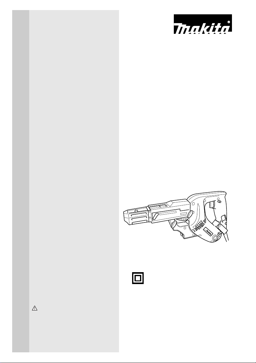
Auto Feed
Screwdriver
MODEL 6833
MODEL 6834
MODEL 6836
DOUBLE
INSULATION
INSTRUCTION MANUAL
WARNING:
For your personal safety, READ and UNDERSTAND before using.
SAVE THESE INSTRUCTIONS FOR FUTURE REFERENCE.
002607
Page 2
SPECIFICATIONS
Model 6833 6834 6836
Screw strip 4 mm x 25 mm - 41 mm 4 mm x 25 mm - 57 mm 4 mm x 25 mm - 41 mm
No load speed (min-1)
Overall length 364 mm 396 mm 364 mm
Net weight 1.9 kg 1.9 kg 1.9 kg
Safety class
• Due to our continuing programme of research and development, the specifications herein are subject to change
without notice.
• Note: Specifications may differ from country to country.
SYMBOLS
The following show the symbols used for the equipment.
Be sure that you understand their meaning before use.
...................Read instruction manual.
...................DOUBLE INSULATION
..................Only for EU countries
Do not dispose of electric equipment
together with household waste
material!
In observance of European Directive
2002/96/EC on waste electric and
electronic equipment and its
implementation in accordance with
national law, electric equipment that
have reached the end of their life
must be collected separately and
returned to an environmentally
compatible recycling facility.
Intended use
The tool is intended for screw driving in wood, metal and
plastic.
Power supply
The tool should be connected only to a power supply of
the same voltage as indicated on the nameplate, and
can only be operated on single-phase AC supply. They
are double-insulated in accordance with European
Standard and can, therefore, also be used from sockets
without earth wire.
For Model 6833
For European countries only
Noise and Vibration
The typical A-weighted sound pressure level is 80 dB (A).
Uncertainty is 3 dB(A).
The noise level under working may exceed 85 dB (A).
– Wear ear protection. –
The typical weighted root mean square acceleration
value is not more than 2.5 m/s
2
2
.
4,700 2,800 6,000
/II
END201-2
These values have been obtained according to
EN60745.
For Model 6834
For European countries only
Noise and Vibration
The typical A-weighted sound pressure level is 81 dB (A).
Uncertainty is 3 dB(A).
The noise level under working may exceed 85 dB (A).
– Wear ear protection. –
The typical weighted root mean square acceleration
value is not more than 2.5 m/s
2
.
These values have been obtained according to
EN60745.
For Model 6836
For European countries only
Noise and Vibration
The typical A-weighted sound pressure level is 83 dB (A).
Uncertainty is 3 dB(A).
The noise level under working may exceed 85 dB (A).
– Wear ear protection. –
The typical weighted root mean square acceleration
value is not more than 2.5 m/s
2
.
These values have been obtained according to
EN60745.
EC-DECLARATION OF CONFORMITY
We declare under our sole responsibility that this product
is in compliance with the following standards of standardized documents, EN60745, EN55014, EN61000 in
accordance with Council Directives, 89/336/EEC, 98/37/
EC.
Yasuhiko Kanzaki CE 2005
Director
MAKITA INTERNATIONAL EUROPE LTD.
Michigan Drive, Tongwell, Milton Keynes, Bucks MK15
8JD, ENGLAND
Responsible manufacturer:
Makita Corporation Anjo Aichi Japan
Page 3

GENERAL SAFETY RULES GEA001-3
WARNING:
Read all instructions. Failure to follow all instructions listed below may result in
electric shock, fire and/or serious injury. The term “power tool” in all of the
warnings listed below refers to your mains-operated (corded) power tool or batteryoperated (cordless) power tool.
SAVE THESE INSTRUCTIONS
Wor k area safety
1. Keep work area clean and well lit. Cluttered and
dark areas invite accidents.
2. Do not operate power tools in explosive atmos-
pheres, such as in the presence of flammable
liquids, gases or dust. Power tools create sparks
which may ignite the dust or fumes.
3. Keep children and bystanders away while oper-
ating a power tool. Distractions can cause you to
lose control.
Electrical safety
4. Power tool plugs must match the outlet. Never
modify the plug in any way. Do not use any
adapter plugs with earthed (grounded) power
tools. Unmodified plugs and matching outlets will
reduce risk of electric shock.
5. Avoid body contact with earthed or grounded
surfaces such as pipes, radiators, ranges and
refrigerators. There is an increased risk of electric
shock if your body is earthed or grounded.
6. Do not expose power tools to rain or wet condi-
tions. Water entering a power tool will increase the
risk of electric shock.
7. Do not abuse the cord. Never use the cord for
carrying, pulling or unplugging the power tool.
Keep cord away from heat, oil, sharp edges or
moving parts. Damaged or entangled cords
increase the risk of electric shock.
8. When operating a power tool outdoors, use an
extension cord suitable for outdoor use. Use of a
cord suitable for outdoor use reduces the risk of
electric shock.
Personal s afety
9. Stay alert, watch what you are doing and use
common sense when operating a power tool. Do
not use a power tool while you are tired or under
the influence of drugs, alcohol or medication. A
moment of inattention while operating power tools
may result in serious personal injury.
10. Use safety equipment. Always wear eye protection. Safety equipment such as dust mask, non-skid
safety shoes, hard hat, or hearing protection used
for appropriate conditions will reduce personal injuries.
11. Avoid accidental starting. Ensure the switch is
in the off-position before plugging in. Carrying
power tools with your finger on the switch or plugging in power tools that have the switch on invites
accidents.
12. Remove any adjusting key or wrench before
turning the power tool on. A wrench or a key left
attached to a rotating part of the power tool may
result in personal injury.
13. Do not overreach. Keep proper footing and balance at all times. This enables better control of the
power tool in unexpected situations.
14. Dress properly. Do not wear loose clothing or
jewellery. Keep your hair, clothing, and gloves
away from moving parts. Loose clothes, jewellery
or long hair can be caught in moving parts.
15. If devices are provided for the connection of
dust extraction and collection facilities, ensure
these are connected and properly used. Use of
these devices can reduce dust-related hazards.
Power tool use and care
16. Do not force the power tool. Use the correct
power tool for your application. The correct
power tool will do the job better and safer at the rate
for which it was designed.
17. Do not use the power tool if the switch does not
turn it on and off. Any power tool that cannot be
controlled with the switch is dangerous and must be
repaired.
18. Disconnect the plug from the power source and/
or the battery pack from the power tool before
making any adjustments, changing accessories,
or storing power tools. Such preventive safety
measures reduce the risk of starting the power tool
accidentally.
3
Page 4

19. Store idle power tools out of the reach of children and do not allow persons unfamiliar with
the power tool or these instructions to operate
the power tool. Power tools are dangerous in the
hands of untrained users.
20. Maintain power tools. Check for misalignment or
binding of moving parts, breakage of parts and
any other condition that may affect the power
tools operation. If damaged, have the power tool
repaired before use. Many accidents are caused
by poorly maintained power tools.
21. Keep cutting tools sharp and clean. Properly
maintained cutting tools with sharp cutting edges
are less likely to bind and are easier to control.
22. Use the power tool, accessories and tool bits
etc. in accordance with these instructions and in
the manner intended for the particular type of
power tool, taking into account the working conditions and the work to be performed. Use of the
power tool for operations different from those
intended could result in a hazardous situation.
Service
23. Have your power tool serviced by a qualified
repair person using only identical replacement
parts. This will ensure that the safety of the power
tool is maintained.
24. Follow instruction for lubricating and changing
accessories.
25. Keep handles dry, clean and free from oil and
grease.
SPECIFIC SAFETY RULES GEB017-1
DO NOT let comfort or familiarity with product (gained from repeated use)
replace strict adherence to screwdriver safety rules. If you use this power
tool unsafely or incorrectly, you can suffer serious personal injury.
1. Hold power tools by insulated gripping surfaces
when performing an operation where the cutting
tool may contact hidden wiring or its own cord.
Contact with a “live” wire will make exposed metal
parts of the tool “live” and shock the operator.
2. Always be sure you have a firm footing.
Be sure no one is below when using the tool in
high locations.
3. Hold the tool firmly.
4. Keep hands away from rotating parts.
5. Do not touch the bit or the workpiece immedi-
ately after operation; they may be extremely hot
and could burn your skin.
SAVE THESE INSTRUCTIONS.
WARNING:
MISUSE or failure to follow the safety rules stated in this instruction manual
may cause serious personal injury.
4
Page 5

FUNCTIONAL
DESCRIPTION
1. Lock button
2. Switch trigger
1. Reversing switch
1
002629
1
2
002636
002648
CAUTION:
• Always be sure that the tool is switched off and unplugged before
adjusting or checking function on the tool.
Switch action
CAUTION:
• Before plugging in the tool, always check to see that the switch trigger
actuates properly and returns to the “OFF” position when released.
To start the tool, simply pull the switch trigger. Release the switch trigger to
stop.
For continuous operation, pull the switch trigger and then push in the lock button.
To stop the tool from the locked position, pull the switch trigger fully, then
release it.
Reversing switch action
CAUTION:
• Always check the direction of rotation before operation.
• Use the reversing switch only after the tool comes to a complete stop.
Changing the direction of rotation before the tool stops may damage the
tool.
This tool has a reversing switch to change the direction of rotation. Press the
upper side (FWD side) of the reversing switch for clockwise rotation or the
lower side (REV side) of the reversing switch for counterclockwise rotation.
Hook
The hook is convenient for hooking the tool to your belt. It can be installed on
either side of the tool. To remove it, pull it out in the direction of the arrow while
raising. To install the hook, push it down until it “clicks” into place on the tool.
1
1. Hook
5
Page 6

ASSEMBLY
1
2
1. Casing
2. Thumb screw
3
1. Dust cover
2. Plane bearing
3. Bit
1
1. Lever
2. Stopper base
3. Plate
4. Casing
12
002657
002663
2
3
4
CAUTION:
• Always be sure that the tool is switched off and unplugged before
carrying out any work on the tool.
Installing or removing the bit
Loosen the thumb screws which secure the casing. Pull out the casing in the
002656
direction of the arrow.
Press the dust cover toward the plain bearing and pull out the bit. If the dust
cover cannot be moved as far as the plain bearing, try it again after turning the
bit slightly.
To install the bit, insert it into the socket while turning it slightly. After installing,
always make sure that the bit is securely held in place by trying to pull it out.
Setting for desired screw length
There are 3 (for Model 6833 & 6836) or 5 (for Model 6834) positive-lock screw
length settings. To obtain the desired setting, pull out the stopper base while
depressing the lever until you see the number of the desired screw length
(indicated on the plate) appear to rest on the very top edge of the casing. See
the table below for the relation between the number indicated on the plate and
the respective screw length ranges.
Number indicated on the plate Screw length range
25/28 25 mm - 28 mm
32 28 mm - 35 mm
40 35 mm - 41 mm
* 51 41 mm - 51 mm
* 57 51 mm - 57 mm
(Note) * for Model 6834 only
006404
6
Page 7

5mm
2
B
3
A
1. Stopper base
2. Casing
3. Adjusting knob
1. Feeder box
2. Screw strip
3. Screw guide
004177
Adjusting the driving depth
1
Depress the stopper base as far as it will go. While keeping it in this position,
turn the adjusting knob until the bit tip projects approx. 5 mm from the stopper
base. Drive a trial screw. If the screw head projects above the surface of the
workpiece, turn the adjusting knob in the “A” direction; if the screw head is
counter-sunk, turn the adjusting knob in the “B” direction.
002666
Installing screw strip
Insert the screw strip through the screw guide. Then insert it through the
1
2
feeder box until the first screw reaches the position next to the driving position.
3
002667
1. Driving position
1
7
Page 8

1
1. Reverse button
1
1. Extension handle
002668
Removing screw strip
To remove the screw strip, just pull it out in the direction of the arrow. If you
depress the reverse button, you can pull out the screw strip in the reverse
direction of the arrow.
002669
002671
Extension handle (optional accessory)
Use of extension handle allows you to drive screws into floors while standing.
OPERATION
8
002676
Driving operation
Switch on the tool by pressing the switch trigger and at the same time pushing
the lock button. Hold the tool squarely against the workpiece and apply forward pressure to the tool. The screw will be automatically carried to the driving
position and driven into the workpiece.
NOTE:
• Do not fire the tool without screws. This will damage the workpiece.
• If the feeder box becomes sluggish in operation, spray car wax (spray
type wax) on its sliding surfaces. Never lubricate it.
Page 9

1
15mm
1. Wall
2. Stopper base
004186
Driving in corner
This tool can be used to drive at a position 15 mm away from the wall as
2
shown in the figure.
CAUTION:
• Driving at a position closer than 15 mm to the wall or driving with the
stopper base in contact with the wall may damage the screw heads and
cause wear on the bit. This may also lead to poor fastening of screws
and malfunction of the tool.
MAINTENANCE
001145
1
1. Limit mark
002686
1
2
1. Screwdriver
2. Brush holder cap
CAUTION:
• Always be sure that the tool is switched off and unplugged before
attempting to perform inspection or maintenance.
Replacing carbon brushes
Remove and check the carbon brushes regularly. Replace when they wear
down to the limit mark. Keep the carbon brushes clean and free to slip in the
holders. Both carbon brushes should be replaced at the same time. Use only
identical carbon brushes.
Use a screwdriver to remove the brush holder caps. Take out the worn carbon
brushes, insert the new ones and secure the brush holder caps.
To maintain product SAFETY and RELIABILITY, repairs, any other maintenance or adjustment should be performed by Makita Authorized Service Centers, always using Makita replacement parts.
ACCESSORIES
CAUTION:
• These accessories or attachments are recommended for use with your Makita tool specified in this manual. The
use of any other accessories or attachments might present a risk of injury to persons. Only use accessory or
attachment for its stated purpose.
If you need any assistance for more details regarding these accessories, ask your local Makita service center.
• Phillips bit
• Drywall screw strips
• Extension handle
• Plastic carrying case
9
Page 10

Memo
10
Page 11

Memo
11
Page 12

884144D228
Makita Corporation Anjo, Aichi, Japan
 Loading...