

Makita 6827 REMPLACEMENT PARTS
GB
Screwdriver Instruction Manual
F
Visseuse Manuel d’instructions
D
Schrauber Betriebsanleitung
I
Avvitatrice Istruzioni per l’uso
NL
Schroevedraaier Gebruiksaanwijzing
E
Atornillador Manual de instrucciones
P
Aparafusadora Manual de instruções
DK
Skruemaskine Brugsanvisning
S
Momentskruvdragare Bruksanvisning
N
Skrutrekker Bruksanvisning
SF
Ruuvinväännin Käyttöohje
GR Κατσαβίδι Οδηγίες χρήσεως
6827
1
2
1
3
4
12
1 mm
1 mm
34
3
2
5
4
6
56
A
B
7
78
2
A
8
B
910
3

Symbols
The following show the symbols used for the tool. Be sure that you understand their meaning before use.
Symboles
Nous donnons ci-dessous les symboles utilisés pour l’outil. Assurez-vous que vous en avez bien compris la signification avant d’utiliser l’outil.
Symbole
Die folgenden Symbole werden für die Maschine verwendet. Machen Sie sich vor der Benutzung unbedingt mit ihrer
Bedeutung vertraut.
Symboli
Per questo utensile vengono usati i simboli seguenti. Bisogna capire il loro significato prima di usare l’utensile.
Symbolen
Voor dit gereedschap worden de volgende symbolen gebruikt. Zorg ervoor dat u de betekenis van deze symbolen
begrijpt alvorens het gereedschap te gebruiken.
Símbolos
A continuación se muestran los símbolos utilizados con esta herramienta. Asegúrese de que entiende su significado
antes de usarla.
Símbolos
O seguinte mostra os símbolos utilizados para a ferramenta. Certifique-se de que compreende o seu significado antes
da utilização.
Symboler
Nedenstående symboler er anvendt i forbindelse med denne maskine. Vær sikker på, at De har forstået symbolernes
betydning, før maskinen anvendes.
Symboler
Det följande visar de symboler som används för den här maskinen. Se noga till att du förstår deras innebörd innan
maskinen används.
Symbolene
Følgende viser de symblene som brukes for maskinen. Det er viktig å forstå betydningen av disse før maskinen tas i
bruk.
Symbolit
Alla on esitetty koneessa käytetyt symbolit. Opettele näiden merkitys, ennen kuin käytät konetta.
Σύµβολα
Τα ακλουθα δείχνουν τα σύµβολα που χρησιµοποιούνται για το µηχάνηµα. Βεβαιωθείτε τι καταλαβαίνετε
τη σηµασία τους πριν απ τη χρήση.
❏ Read instruction manual.
❏ Lire le mode d’emploi.
❏ Bitte Betriebsanleitung lesen.
❏ Leggete il manuale di istruzioni.
❏ Lees de gebruiksaanwijzing.
❏ Lea el manual de instrucciones.
❏ DOUBLE INSULATION
❏ DOUBLE ISOLATION
❏ DOPPELT SCHUTZISOLIERT
❏ DOPPIO ISOLAMENTO
❏ DUBBELE ISOLATIE
❏ DOBLE AISLAMIENTO
❏ Leia o manual de instruções.
❏ Læs brugsanvisningen.
❏ Läs bruksanvisningen.
❏ Les bruksanvisingen.
❏ Katso käyttöohjeita.
❏ ∆ιαβάστε τις οδηγίες χρήσης
❏ DUPLO ISOLAMENTO
❏ DOBBELT ISOLATION
❏ DUBBEL ISOLERING
❏ DOBBEL ISOLERING
❏ KAKSINKERTAINEN ERISTYS
❏ ∆ΙΠΛΗ ΜΟΝΩΣΗ
4

ENGLISH
1 Front cap
2 Locator
3 Adjusting ring
Explanation of general view
4 Pointer
5 Switch trigger
6 Lock button
7 Reve rsing swit ch lever
8Hook
SPECIFICATIONS
Model 6827
Capacities
Self drilling screw ................................................. 6 mm
Machine screw ..................................................... 8 mm
Wood screw ...................................................... 6.2 mm
No load speed (min
Overall length .................................................... 304mm
Net weight .............................................................. 1.8 kg
• Due to our continuing program of research and devel-
opment, the specifications herein are subject to change
without notice.
• Note: Specifications may differ from country to countr y.
Intended use
The tool is intended for screw driving in wood, metal and
plastic.
Power supply
The tool should be connected only to a power supply of
the same voltage as indicated on the nameplate, and can
only be operated on single-phase AC supply. They are
double-insulated in accordance with European Standard
and can, therefore, also be used from sockets without
earth wire.
Safety hints
For your own safety, please refer to the enclosed safety
instructions.
–1
) ...................................... 0 – 2,500
ADDITIONAL SAFETY RULES
1. Hold tool by insulated gripping surfaces when
performing an operation where the cutting tools
may contact hidden wiring or its own cord. Contact with a “live” wire will make exposed metal
parts of the tool “live” and shock the operator.
2. Always be sure you have a firm footing. Be sure
no one is below when using the tool in high locations.
3. Hold the tool firmly.
4. Keep hands away from rotating parts.
5. Do not touch the bit or the workpiece immedi-
ately after operation; they may be extremely hot
and could burn your skin.
ENB004-1
SAVE THESE INSTRUCTIONS.
OPERATING INSTRUCTIONS
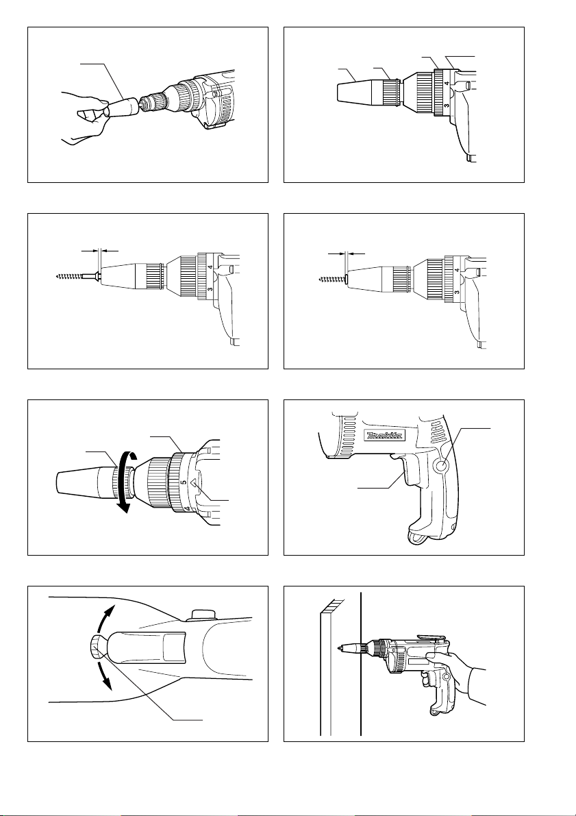
Removing or installing the bit (Fig. 1)
Important:
Always be sure that the tool is switched off and
unplugged before removing or installing the bit.
To remove the bit, first pull the front cap off and then pull
the bit firmly. To install the bit, insert it into the tool as far
as it will go and then replace the front cap.
Depth adjustment (Fig. 2, 3 & 4)
When you wish to drive self drilling screws, etc., adjust
the depth as follows.
Turn the locator to adjust the depth.
Initially, adjust the locator to create a distance of approximately 1 mm from the tip of the front cap (which works in
conjunction with the locator) to the base of the screw
head. One full turn of the locator equals 1 mm change in
depth. After adjusting the locator, turn the adjusting ring
so that the 6" mark is aligned with the pointer on the gear
housing. Drive a trial screw into your material or a piece
of duplicate material. If the depth is not suitable for the
screw, adjust the locator until the proper depth setting is
obtained.
Adjusting fastening torque (Fig. 5)
When you wish to drive machine screws, wood screws,
hex bolts, etc. with the predetermined torque, adjust the
fastening torque as follows.
The fastening torque may be adjusted by turning the
adjusting ring. Before turning the adjusting ring, turn the
locator in the direction of the arrow as far as it will go
without forcing. The torque is increased by tur ning the
adjusting ring in the direction of the arrow and decreased
by turning it in the opposite direction. Align the number 1
on the adjusting ring with the pointer on the gear housing. Drive a trial screw into your material or a piece of
duplicate material. If the fastening torque is not suitable
for the screw, continue adjusting until the proper torque is
obtained.
CAUTION:
The adjusting ring should be turned only within the numbered range. It should not be forced beyond this range.
Switch action (Fig. 6)
CAUTION:
Before plugging in the tool, always check to see that the
switch trigger actuates properly and returns to the “OFF”
position when released.
To start the tool, simply pull the trigger. Tool speed is
increased by increasing pressure on the trigger. Release
the trigger to stop. For continuous operation, pull the trigger and then push in the lock button. To stop the tool from
the locked position, pull the trigger fully, then release it.
NOTE:
Even with the switch on and motor running, the bit will not
rotate until you fit the point of the bit in the screw head
and apply forward pressure to engage the clutch.
5

Reversing switch action (Fig. 7)
CAUTION:
• Always check the direction of rotation before opration.
• Use the reversing switch only after the tool comes to a
complete stop. Changing the direction of rotation
before the tool stops may damage the tool.
This tool has a reversing switch to change the direction of
rotation. Move the reversing switch lever to the “A” side
for clockwise rotation or the “B” side for counterclockwise
rotation.
Operation (Fig.8)
Fit the screw on the point of the bit and place the point of
the screw on the surface of the workpiece to be fastened.
Apply presssure to the tool and star t it. Withdraw the tool
as soon as the clutch cuts in. Then release the trigger.
CAUTION:
• When fitting the screw onto the point of the bit, be careful not to push in on the screw. If the screw is pushed
in, the clutch will engage and the screw will rotate suddenly. This could damage a workpeice or cause an
injury.
• Make sure that the bit is inserted straight in the screw
head, or the screw and/or bit may be damaged.
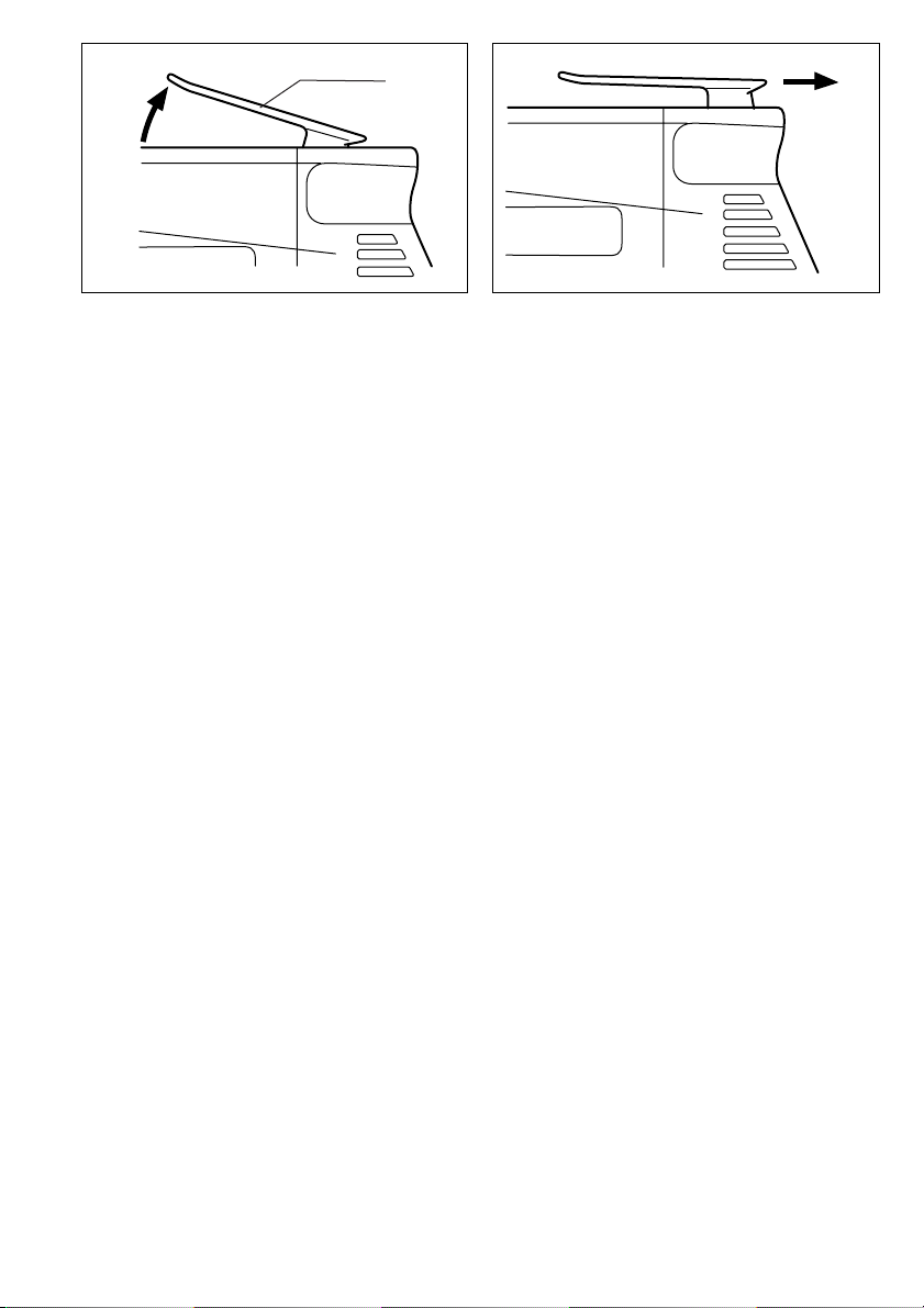
Hook (Fig. 9 & 10)
The hook is convenient for temporarily hanging the tool.
When using the hook, pull it out in “A” direction and then
push it in B direction to secure in place.
When not using the hook, return it back to its initial position by following the above procedures in reverse.
MAINTENANCE
CAUTION:
Always be sure that the tool is switched off and
unplugged before carrying out any work on the tool.
To maintain product safety and reliability, repairs, maintenance or adjustment should be carried out by a Makita
Authorized Service Center.
6

FRANÇAIS
1 Positionneur
2 Bague
3 Molette de réglage
Descriptif
4 Index
5 Gâchette d’interrupteur
6 Bouton de blocage
7 Inverseur
8 Clip d’accrochage
SPECIFICATIONS
Modèle 6827
Capacités
Vis auto-foreuses ................................................ 6 mm
Vis à tête hexagonale .......................................... 8 mm
Vis à bois .......................................................... 6,2 mm
Vitesse à vide (min
Longueur hors tout ............................................ 304 mm
Pois net .................................................................. 1,8kg
• Etant donné l’évolution constante de notre programme
de recherche et de développement, les spécifications
contenues dans ce manuel sont sujettes à modification
sans préavis.
• Note : Les spécifications peuvent varier suivant les
pays.
Utilisations
L'outil est conçu pour le vissage dans le bois, le métal et
le plastique.
Alimentation
L’outil ne devra être raccordé qu’à une alimentation de la
même tension que celle qui figure sur la plaque signalétique, et il ne pourra fonctionner que sur un courant secteur monophasé. Réalisé avec une double isolation, il est
conforme à la réglementation européenne et peut de ce
fait être alimenté sans mise à la terre.
Consignes de sécurité
Pour votre propre sécurité, repor tez-vous aux consignes
de sécurité qui accompagnent l’outil.
-1
) ....................................... 0–2500
CONSIGNES DE SECURITE
SUPPLEMENTAIRES
1. Tenez l’outil par ses surfaces de saisie isolées
lorsque vous effectuez une opération au cours
de laquelle l’outil tranchant risque d’entrer en
contact avec un fil caché ou avec son propre
cordon. Le contact avec un fil électrique sous
tension mettra les parties métalliques non isolées de l’outil sous tension et électrocutera l’utilisateur.
2. Veillez à garder toujours une bonne assise.
Assurez-vous que personne ne se trouve audessous de vous quand vous utilisez l’outil
d’une situation élevée.
3. Tenez votre outil fermement.
4. Gardez les mains éloignées des pièces en mou-
vement.
5. Ne touchez ni la vis ni son support immédiate-
ment après un vissage. Ils peuvent être extrêmement chauds et risquer de vous brûler.
CONSERVEZ CES INSTRUCTIONS.
MODE D’EMPLOI
Pose et dépose du embout (Fig. 1)
Important :
Avant d’installer ou de relirer l’embout, assurez-vous que
le contact soit coupé et l’outil débranché.
Pour retirer l’embout, retirez d’abord le positionneur et
tirez ensuite fermement sur l’embout. Pour installer
l’embout, insérez-le dans l’outil aussi loin que possible et
replacez le positionneur.
Réglage de profondeur (Fig. 2, 3 et 4)
Quand vous voulez enfoncer des vis auto-foreuse, etc.,
réglez la profondeur comme suit.
Faites tourner le positionneur pour ajuster la profondeur.
Ajustez d’abord la bague filetée de façon à laisser une
distance d’environ 1 mm entre l’extrémité du positionneur
et le plat de la tête de vis. Un tour complet du positionneur entraîne une variation de 1 mm de profondeur. Une
fois le positionneur réglé, tournez la bague de réglage de
façon que la marque “6” se trouve alignée sur l’index du
carter. Enfoncez une vis d’essai dans votre support ou
dans un échantillon analogue; si la profondeur ne convient pas à la vis, pour-suivez le réglage jusqu’à ce que
la profondeur correcte soit obtenue.
Réglage du couple de serrage (Fig. 5)
Si vous désirez enfoncer des vis à métaux ou à bois, des
boulons six-pans, etc. avec un couple préréglé, effectuez
ce réglage comme suite.
Le couple de serrage peut être ajusté en tournant la
bague de réglage. Avant de la tour ner toutefois, faites
tourner le positionneur dans la direction de la flèche
aussi loin qu’il est possible de le faire sans forcer. Le couple se trouve accru quand vous tournez la bague dans le
sens le la flèche, et diminué quand vous la tournez dans
le sens opposé. Alignez le No1 de la bague de réglage
sur l’index que porte le carter de l’outil. Enfoncez une vis
d’essai dans votre matériau ou un matériau équivalent.
Si le couple de serrage ne vous semple pas adéquat,
continuez le réglage jusqu’à ce qu’il se trouve atteint.
AT T E N TI O N :
La bague de réglage ne doit être manoeuvrée que dans
la limite des chiffres et ne doit jamais être forcée au-delà.
7

Utilisation de la gâchette (Fig. 6)
ATTENTION :
Avant de brancher l’outil sur le secteur, vérifiez toujours
que la gâchette fonctionne correctement et qu’elle revient
sur la position “OFF” quand vous la relâchez.
Pour mettre l’outil en route, tirez simplement sur la
gâchette. La vitesse augmente avec la pression exercée
sur la gâchette. Pour arrêter l’outil, relâchez la gâchette.
Pour une utilisation continue, tirez sur la gâchette et
appuyez sur le bouton de blocage. Pour arrêter l’outil
pendant une utilisation continue, tirez à fond sur la
gâchette puis relâchez-la.
NOTE :
Même si l’interrupteur est enclenché et que le moteur
tourne, l’embout ne tournera pas tant que vous n’aurez
pas inséré la pointe de l’embout dans la tête de vis et
que vous n’exercerez pas de pression vers l’avant pour
engager l’embrayage.
Inverseur (Fig.7)
ATTENTION :
• Vérifiez toujours le sens de rotation avant de mettre
l’outil en marche.
• N’actionnez l’inverseur qu’une fois que l’outil est complètement arrêté. Si vous changez le sens de rotation
avant l’arrêt de l’outil, vous risquez de l’endommager.
L’outil possède un inverseur qui permet de changer le
sens de rotation. Déplacez le levier d’inverseur sur le
côté “A” pour obtenir une rotation vers la droite, et sur le
côté “B” pour obtenir une rotation vers la gauche.
Pour visser (Fig.8)
Placez la vis à l’extrémité de l’embout et appliquez la
pointe de la vis contre la surface de la pièce à visser.
Exercez une pression sur l’outil et appuyez sur la
gachette. Retirez l’outil dès que la vis est complètement
enfoncée. Puis, relâchez la gâchette.
ATTENTION :
• Quand vous fixez la vis sur la pointe de l’embout, faites
attention de ne pas enfoncer la vis. Si la vis s’enfonce,
l’embrayage s’engagera et la vis se mettra brusquement à tourner, ce qui pourrait endommager la pièce
ou provoquer des blessures.
• Vérifiez que l’embout soit inséré le plus droit possible
sur la tête de vis, sinon la vis et/ou l’embout pourraient
être endommagés.
Clip d’accrochage (Fig. 9 et10)
Le clip d’accrochage est pratique pour accrocher temporairement l’outil. Pour utiliser le clip d’accrochage, sortezle en le tirant dans le sens “A”, puis poussez-le dans le
sens “B” pour le fixer en position.
Quand vous ne vous servez pas du clip d’accrochage,
ramenez-le à sa position initiale en procédant dans
l’ordre inverse des explications ci-dessus.
ENTRETIEN
ATTENTION :
Avant toute intervention, assurez-vous que le contact soit
coupé et l’outil débranché.
Pour maintenir la sécurité et la fiabilité du produit, les
réparations, l’entretien ou les réglages doivent être effectués par le Centre d’Entretien Makita.
8

DEUTSCH
1 Führungshülse
2 Feststellhülse
3 Drehmoment-Einstellring
Übersicht
4 Markierungspfeil
5 Elektronikschalter
6 Schalterarretierung
7 Drehrichtungsumschalter
8 Gürtelclip
TECHNISCHE DATEN
Modell 6827
Maße
Selbstbohrschrauben .......................................... 6 mm
Maschinenschrauben .......................................... 8 mm
Holzschrauben .................................................. 6,2mm
Leerlaufdrehzahl/min.(min
Gesamtlänge ..................................................... 304 mm
Nettogewicht .......................................................... 1,8 kg
• Wir behalten uns vor, Änderungen im Zuge der Ent-
wicklung und des technischen Fortschritts ohne vorhe-
rige Ankündigung vorzunehmen.
• Hinweis: Die technischen Daten können von Land zu
Land abweichen.
Vorgesehene Verwendung
Das Werkzeug ist für das Eindrehen von Schrauben in
Holz, Metall und Kunststoff vorgesehen.
Netzanschluß
Die Maschine darf nur an die auf dem Typenschild angegebene Netzspannung angeschlossen werden und
arbeitet nur mit Einphasen-Wechselspannung. Sie ist
entsprechend den Europäischen Richtlinien doppelt
schutzisoliert und kann daher auch an Steckdose ohne
Erdanschluß betrieben werden.
Sicherheitshinweise
Lesen und beachten Sie diese Hinweise, bevor Sie das
Gerät benutzen.
-1
) ............................ 0–2500
ZUSÄTZLICHE
SICHERHEITSBESTIMMUNGEN
1. Beim Bohren und Schrauben in Wände, Fußbö-
den oder sonstige Stellen, an denen sich stromführende Leitungen befinden könnten, nicht die
Metallteile der Maschine oder des Einsatzwerkzeuges berühren. Die Maschine nur an den isolierten Griffflächen festhalten, um bei einem
Kontakt mit einer stromführenden Leitung einen
elektrischen Schlag zu vermeiden.
2. Sorgen Sie für sicheren Stand und halten Sie
jederzeit Gleichgewicht. Stellen Sie sicher, dass
sich bei Einsatz der Maschine an hochgel egenen Arbeitsplätzen keine Personen darunter aufhalten.
3. Halten Sie die Maschine fest.
4. Halten Sie die Hände von rotierenden Teilen fern.
5. Das Einsatzwerkzeug oder das bearbeitete Werk-
stück nicht unmittelbar nach Beendigung der
Arbeit berühren. Sie können sehr heiß sein und
Verbrennungen verursachen.
BEWAHREN SIE DIESE HINWEISE
SO R GF Ä LTI G AUF.
BEDIENUNGSHINWEISE
Montage bzw. Demontage von
Einsatzwerkzeugen (Abb.1)
VORSICHT:
Vergewissern Sie sich vor der Montage bzw. Demontage
von Einsatzwerkzeugen stets, dass die Maschine abgeschaltet und der Netzstecker gezogen ist.
Zur Demontage von Einsatzwerkzeugen entfernen Sie
zuerst die Führungshülse und ziehen Sie dann das Einssatzwerkzeug mit einem kräftigen Ruck heraus. Zur Montage das Einsatzwerkzeug so weit wie möglich in die
Maschine einsetzen, anschließend die Führungshülse
wieder aufsetzen.
Tiefenbegrenzung (Abb. 2,3 u. 4)
Drehen Sie die Feststellhülse zur Einstellung der Tiefenbegrenzung. Zur Grundeinstellung sollte das Einsatzwerkzeug ca. 1 mm aus der Führungshülse herausragen.
Führen Sie eine Probeverschraubung durch. Zur weiteren Einstellung drehen Sie die Feststellhülse nach rechts
für größere Schraubtiefe oder nach links für eine geringere Schraubtiefe. Dabei bewirkt eine Umdrehung der
Feststellhülse eine Veränderung der Tiefeneinstellung
von 1 mm. Die Drehmomenteinstellung sollte bei dieser
Verschraubungsart auf Stufe 6 eingestellt werden.
Einstellung des Drehmoments (Abb. 5)
Zum Verschrauben von Maschinen-, Holz-, Sechskantschrauben u. ä. stellen Sie das gewünschte Drehmoment
wie folgt ein:
Die Feststellhülse ohne Kraftaufwand bis zum Anschlag
in Pfeilrichtung verstellen, um die Tiefenbegrenzung auszuschalten. Die Zahl 1 auf dem Drehmoment-Einstellring
auf den Markierungspfeil (Getriebegehäuse) ausrichten.
Eine Probeverschraubung durchführen. Sollte das Drehmoment zu gering sein, die Einstellung mit einem höheren Zahlenwert wiederholen. Den DrehmomentEinstellring nur innerhalb des Zahlenbereichs ohne
Gewaltanwendung verdrehen.
VORSICHT:
Der Einstellring darf nur innerhalb des nummerier ten
Bereichs gedreht werden. Er sollte nicht über diesen
Bereich hinaus gedreht werden.
9

Schalterfunktion (Abb. 6)
VORSICHT:
Vor dem Anschließen der Maschine an das Stromnetz
stets überprüfen, ob der Elektronikschalter ordnungsgemäß funktioniert und beim Loslassen in die AUS-Stellung
zurückkehrt.
Zum Einschalten drücken Sie den Elektronikschalter.
Zum Ausschalten lassen Sie den Schalter los. Die Drehzahl erhöht sich durch verstärkte Druckausübung auf den
Elektronikschalter. Zum Ausschalten den Schalter loslassen.
Für Dauerbetrieb drücken Sie den Elektronikschalter und
gleichzeitig die Schalterarretierung. Zum Ausschalten
des Dauerbetriebs den Elektronikschalter drücken und
wieder loslassen.
HINWEIS:
Das Einsatzwerkzeug dreht sich nur bei Druckausübung
auf die Maschine. Auch bei eingeschalteter Maschine
und laufendem Motor kuppelt die Maschine ohne Druck
auf das Einsatzwerkzeug nicht ein.
Drehrichtungsumschalter (Abb. 7)
VORSICHT:
• Prüfen Sie stets die Drehrichtung, bevor Sie mit dem
Schraubvorgang beginnen.
• Wechseln Sie niemals die Drehrichtung, bevor der
Motor zum Stillstand gekommen ist. Andernfalls kann
die Maschine beschädigt werden.
Mit dem Drehrichtungsumschalter kann die Drehrichtung
verändert werden. Schalten Sie für Rechtslauf auf A, für
Linkslauf auf B.
Betrieb (Abb.8)
Die Schraube in das Einsatzwerkzeug einsetzen. Mit
Druck auf die Maschine die Verschraubung durchführen.
Den Schraubvorgang beenden, sobald die Kupplung
ausrastet. Dann den Elektronikschalter loslassen.
VORSICHT:
• Die Schraube beim Einsetzen in das Einsatzwerkzeug
nicht andrücken, da die Gefahr besteht, dass die Kupplung einrastet und die Schraube sich dreht. Verletzungen oder Beschädigungen der Werkstückoberfläche
könnten verursacht werden.
• Das Einsatzwerkzeug senkrecht in den Schraubenkopf
setzen, um eine Beschädigung von Schraubenkopf und
Einsatzwerkzeug zu vermeiden. Vermeiden Sie unnötiges Ein- und Auskuppeln.
Gürtelclip (Abb. 9 und 10)
Der Gürtelclip ist praktisch, um die Maschine vorübergehend aufzuhängen. Den Gürtelclip zur Benutzung in
Richtung “A” herausziehen und dann zur Sicherung in
Richtung “B” schieben.
Wenn der Gürtelclip nicht benutzt wird, ist er durch
Umkehren des obigen Verfahrens in seine Ausgangsstellung zurückzustellen.
WARTUNG
VORSICHT:
Vor Arbeiten an der Maschine vergewissern Sie sich, daß
sich der Schalter in der ,,OFF-Position” befindet und der
Netzstecker gezogen ist.
Um die Sicherheit und Zuverlässigkeit dieser Maschine
zu gewährleisten, sollten Reparatur-, Wartungs-, und
Einstellarbeiten nur von Makita autorisierten Werkstätten
oder Kundendienstzentren unter ausschließlicher Verwendung von Makita-Originalersatzteilen ausgeführt
werden.
10

ITALIANO
1 Copertura frontale
2 Mandrino
3 Anello di regolazione
Visione generale
4 Freccia
5 Grilletto interruttore
6 Bottone di bloccaggio
7 Leva interruttore di inversione
8 Gancio
DATI TECNICI
Modello 6827
Capacità
Vite autoperforante ............................................. 6 mm
Vite per macchinario ............................................8 mm
Vite in legno ...................................................... 6,2 mm
Velocità a vuoto (min
Lunghezza totale ............................................... 304 mm
Peso netto .............................................................. 1,8 kg
• Per il nostro programma di ricerca e sviluppo continui, i
dati tecnici sono soggetti a modifiche senza preavviso.
• Nota: I dati tecnici potrebbero differire a seconda del
paese di destinazione del modello.
Utilizzo specifico dell'utensile
Questo utensile serve ad avvitare le viti nel legno,
metallo e plastica.
Alimentazione
L’utensile deve essere collegato ad una presa di corrente
con la stessa tensione indicata sulla targhetta del nome,
e può funzionare soltanto con la corrente alternata
monofase. Esso ha un doppio isolamento in osservanza
alle norme europee, per cui può essere usato con le
prese di corrente sprovviste della messa a terra.
Consigli per la sicurezza
Per la vostra sicurezza, riferitevi alle accluse istruzioni
per la sicurezza.
-1
) ..................................... 0 – 2.500
REGOLE ADDIZIONALI DI SICUREZZA
1. Tenere l’utensile per le superfici di tenuta isolate
quando si esegue una operazione in cui
potrebbe fare contatto con fili elettrici nascosti o
con il suo stesso cavo di alimentazione. Il contatto con un filo elettrico “sotto tensione” mette
“sotto tensione” le parti metalliche esposte
dell’utensile dando una scossa all’operatore.
2. Assicurarsi di avere i piedi al sicuro continua-
mente. Assicurarsi che non c’è nessuno sotto
quando si fanno lavori in posizioni alte.
3. Mantenere l’utensile fermo.
4. Tenere le mani lontane dalle parti in movimento.
5. Non toccare la punta oppure il pezzo sotto lavo-
razione subito dopo la foratura, potrebbero
essere estremamente caldi e causare ustioni alla
pelle.
CONSERVATE QUESTE ISTRUZIONI.
ISTRUZIONI PER L’USO
Montaggio e smontaggio della punta (Fig. 1)
Importante:
Sempre assicurarsi che l’utensile é staccato dalla presa
di corrente e l’interruttore é staccato prima di montare
oppure smontare la punta.
Per smontare la punta, per prima cosa tirare via la copertura frontale e quindi tirare in fuori la punta con forza. Per
montare la punta, inserirla neell’utensile il più profondamente possibile e quindi rinpiazzare la copertura frontale.
Regolazione della profondità (Fig.2, 3 e 4)
Quando volete piazzare una punta a foratura automatica,
etc., regolare la profondità nel seguente modo:
Far girare il mandrino per regolare la profondità.
All’inizio regolare il mandrino per creare una distanza
approssimativa di 1 mm tra l’estremità della copertura
frontale (che lavora in tandem con il mandrino) e la base
della testa della vite. Un giro completo del mandrino é
uguale a la 1 mm di avanzamento in profondità. Dopo
aver regolato il mandrino, far girare l’anello di regolazione
in modo che il numero 6 venga a trovarsi allineato con
l’indicatore sul porta mandrino. Fare una prova avvitando
una vite su un materiale adatto al caso. Se la profondità
non é quella desiderata, continuare la regolazione finchè
si ottiene la regolazione adatta alla profondità desiderata.
Regolazione della forza di torsione (Fig.5)
Quando desiderate stringere viti per macchinario, viti da
legname bulloni esagonali, etc. con una forza di torsione
predeterminata regolare la forza di torsione nel modo
seguente:
La forza di torsione può essere regolata facendo girare
l’anello di regolazione. Prima di far girare l’anello di regolazione, far girare il mandrino nella direzione della freccia
finché si riesce a farla avanzare senza forzature. La forza
di torsione aumenta facendo girare l’anello di regolazione
nella direzione della freccia e diminuisce facendo girare
l’anello di regolazione nella direzione opposta della freccia. Allineare il numero 1 sull’anello di regolazione con il
segno indicatore sul cor po dell’utensile. Avvitare una vite
prova sul materiale oppure su un pezzo di materiale di
ricambio. Se la forza di torsione non è adatta alla vite,
continuare la regolazione finché si ottiene una forza di
torsione adeguata.
PRECAUZIONI:
L’anello di regolazione dovrà essere girato solo nell’arco
compreso tra i numeri non dovrà essere forzato a uscire
da questi limiti.
11
 Loading...