

Page 1
GB Drywall Screwdriver
Instruction Manual
F Visseuse
D Schrauber
I Avvitatrice
NL Schroevedraaier
E Atornillador
P Chave de parafusos
DK Skruemaskine
S Gipsskruvdragare
N Gipsskrutrekker
SF Ruuvinväännin
GR Κατσαβίδι ξηρού τοίχου Οδηγίες χρήσεως
Manuel d’instructions
Betriebsanleitung
Istruzioni per l’uso
Gebruiksaanwijzing
Manual de instrucciones
Manual de instruções
Brugsanvisning
Bruksanvisning
Bruksanvisning
Käyttöohje
6823
6824
6825
6825R
Page 2
A
2
1
B
3
12
2
3
3
1
34
3
7
4
5
6
56
A
B
8
78
2
Page 3
A
9
B
910
7
11 12
13 14
15
7
3
Page 4

ENGLISH
Explanation of general view
1 Locking sleeve
2 Approximately 1 mm
3 Locator
SPECIFICATIONS
Model 6823 6824 6825 / 6825R
Capacities
Self drilling screw .....................................................................6mm 6mm —
Drywall screw ...........................................................................6 mm 5mm 4mm
No load speed (min
Overall length ..............................................................................301 mm 290mm 290mm
Net weight ...................................................................................1.5kg 1.4kg 1.4kg
• Due to our conti nuing program of rese arch and devel-
opment, the specifications herein are subject to change
without notice.
• Note: Specifications may differ from country to country.
Intended use
The tool is int end ed for scr ew d r ivi ng in wood, metal and
plastic.
Power supply
The tool should be connected o nly to a power s upply of
the same voltage as indicated on the nameplate, and can
only be operated on sing le-phase AC supply. They are
double-insulated in accor dance with E uropean Stand ard
and can, therefore, also be us ed from sockets without
earth wire.
Safety hints
For your own safety, please refer to the en closed safety
instructions.
–1
) ............................... ..................... .............0 – 2,500 0 – 4,500 0 – 6,000
ADDITIONAL SAFETY RULES
1. Always be sure you have a firm footing.
Be sure no one is below wh en using the too l in
high locations.
2. Hold the tool firmly.
3. Keep hands away from rotating parts.
4. When driving into walls, floors or wherever
“live” electrical wires may be encounter ed, DO
NOT TOUCH ANY METAL PARTS OF THE TOOL!
Hold the tool only by the insulated gr aspin g surfaces to prevent electric shock if you drive into a
“live” wire.
5. Do not touch the bit or the workpiece i mmedi-
ately after operati on; they may be extremely hot
and could bu r n your skin.
SAVE THESE INSTRUCTIONS.
4Bit
5 Magnetic bit holder
6 Switch trigger
OPERATING INSTRUCTIONS
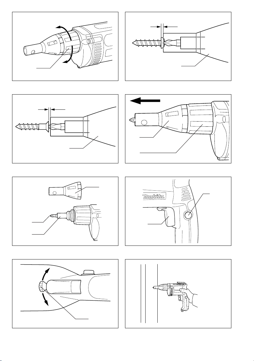
Depth adjustment
The depth can be a djusted by turning th e l ocking s leeve.
Turn it in “A” d irection for less depth an d in “B” dire ction
for more depth. One full tu rn of the locking sleeve equals
1.5 mm change in depth. (Fig. 1) Adjust the locking
sleeve so that the distance b etween t he ti p o f t he l oc ator
and the screw head is approxima tely 1 mm as shown in
Fig. 2 or 3. Drive a trial screw into your material or a
piece of duplicate material. If the depth is still not suitable
for the screw, continue adjusting until you obtain the
proper depth setting. (Fig. 2 & 3)
Removing or installing bit (Fig. 4 & 5)
Important:
Always be sure that the tool is switched off and
unplugged before removing or installing the bit.
To remove the bit, first pull the locator out of the locking
sleev e . Then gr asp th e bit wit h a pair of pli ers and pu ll th e
bit out of the magnetic bit holder. Sometimes, it helps to
wiggle the bit with the pliers as you pull.
To install the bit, push it firmly into the magnetic bit
holder. Then install the locator by pushing it firmly back
onto the lo cking sleeve.
Switch action ( Fig.6)
CAUTION:
Before plugging in the to ol, always check to see tha t the
switch trigger actuates pr oper ly and re tur ns to the “OF F”
position when released.
To start the tool, simply pull the switch trigger. Tool speed
is increased by increasing pressu re on the switch tr i gg er.
Release the switch trigge r to stop. For continuous operation, pull the switch trigger and then pu sh in the lock button. To stop the tool from the locked position, pull the
switch trigger fully, then release it.
NOTE:
Even with the switch on and motor running, the bit will not
rotate until you fit the point o f the bit in the screw head
and apply forward pressure to engage the clutch.
7 Lock button
8 Reversing switch lever
9Hook
4
Page 5

Reversing switch action (Fig. 7)
CAUTION:
• Always check the direction of rotation before opration.
• Use the reversing switch only after the tool comes to a
complete stop. Charging the direction of rotation before
the tool stops may damage the tool.
This tool has a reversing switch to change the direction of
rotation. Move the reversing switch lever to the “A” side
for clockwise rotation or the “B” side for counterc lockwis e
rotation.
Operation
Fit the screw on the point of the bit and place the point of
the screw on the surface of the workpiece to be fastened.
Apply presssure to the tool and start it. Withdraw the tool
as soon as the clutch cuts in. Then release the trigger.
CAUTION:
• When fitting the screw onto the point of the bit, be careful not to push in on the screw. If the screw is pushed
in, the clutch will engage and the screw will rotate suddenly. This could damage a workpeice or cause an
injury.
• M ake sure that th e bit is inse rted straight in the screw
head, or the screw and/or bit may be damaged.
Hook (Fig.9 &10)
The hook is convenient for temporarily hang ing the tool.
When using the hook, pull i t out in “A ” direc tion a nd then
push it in B direction to secure in place.
When not using the h ook, re tur n it back to its ini tial p osition by following the above procedures in reverse.
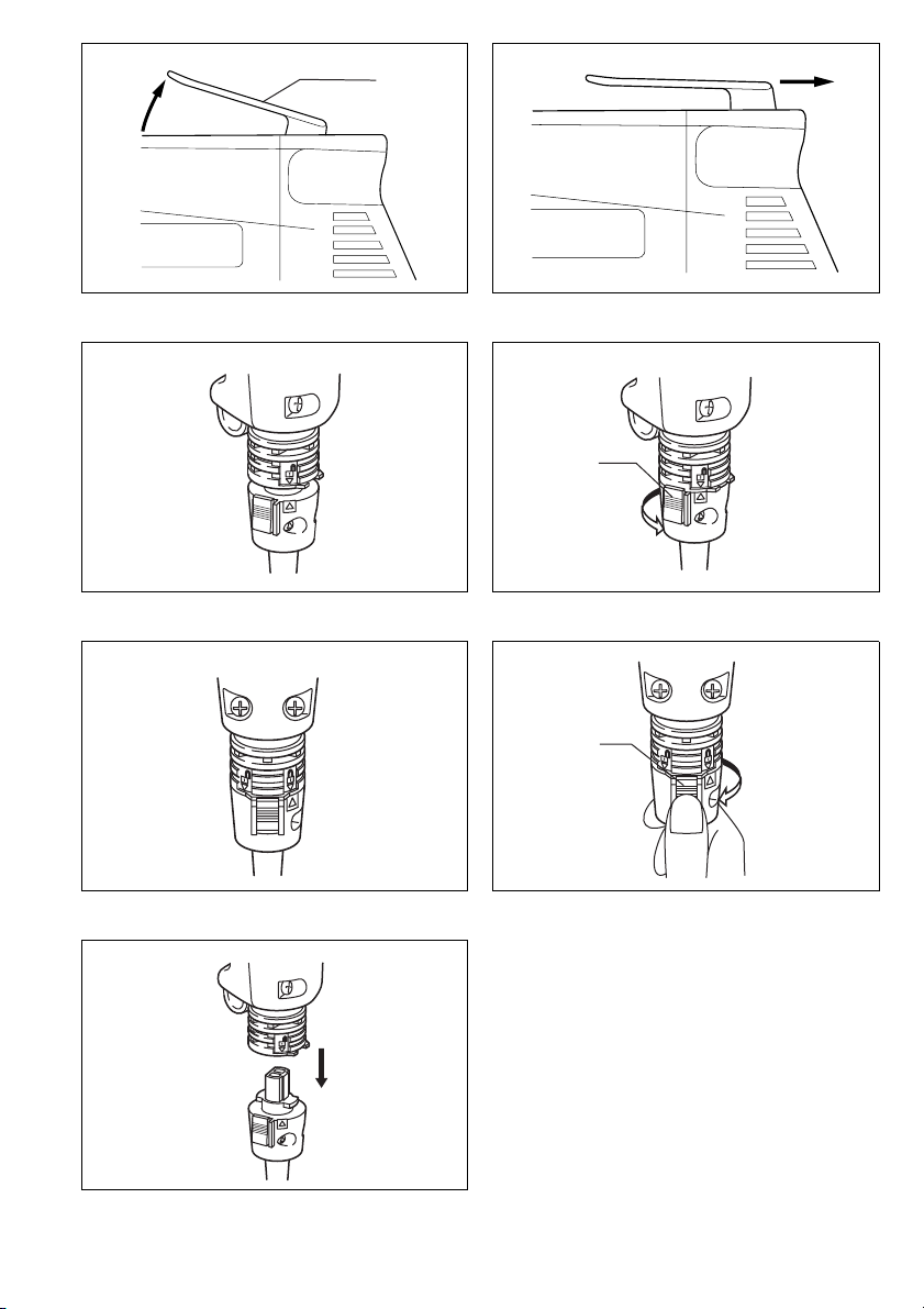
How to install and remove the Removable Cord
Adapter
Important:
Always be sure that the tool is switched off and
unplugged before removing or installing the Removable
Cord Adapter.
How to install and remove the Removable Cord
Adapter
Important:
Always be sure that the tool is switched off and
unplugged before removing or installing the Removable
Cord Adapter.
How to install
Insert the Removable Cord Adapter as far as it goes so
that the markin g on an end of the Removable Cord
Adapter on the side of connecting to power supply cord is
aligned to the marking on the other end of the
Removable Cord Adapter on the side of connecting to the
tool. (Fig. 11)
Turn the Removable Cord Adapter clockwise until it is
locked with a lock button. (Fig. 12)
And at this time the marking on an end of the
Removable Cord Adapter on the sid e of power supply
cord is aligned to the m ark ing on the other end of the
Removable Cord Adapter on the side of connecting to the
tool. (Fig. 13)
How to remove
Rotate the Removable Cord Adapter counterclockwise
until it stops while pressin g the lower pa rt of the lock button. (Fig. 14)
Then pull the R emovable Cord Adapter in th at position.
(Fig. 15)
MAINTENANCE
CAUTION:
Always be sure that the tool is switched off and
unplugged before carrying out any work on the tool.
To maintain product safety and reliability, repairs, maintenance or adjustment should be carried ou t by a Makita
Authorized Service Center.
ACCESSORIES
CAUTION:
• T hese accessories or attac hments are recommended
for use with your Makita tool specifie d in this manual.
The use of any other accessories or attachments might
present a risk of injur y t o persons. O nly use acce ssor y
or attachm ent for its stated purpose.
If you need any assistance for more details regarding
these accessories, ask your local Makita service center.
• Phillips insert bit 1-25, 2-25 and 3-25
• Magnetic bit holder 6.35-76 and 6.35-60
5
Page 6

NEDERLANDS
Verklaring van algemene gegevens
1 Borghuls
2 Ongeveer 1 mm
3 Locator
TECHNISCHE GEGEVENS
Model 6823 6824 6825 / 6825R
Capaciteiten
Zelfborende schroef .................................................................6 mm 6mm —
Gipsplaatschroef ......................................................................6 mm 5mm 4 mm
Toerental onbelast (min
Totale lengte ................................................................................301 mm 290mm 290mm
Netto gewicht ...............................................................................1,5kg 1,4kg 1,4kg
–1
) .............................. ..... ...... ..................0 – 250 0 0 – 4500 0 – 6000
4Bit
5 Magnetische bithouder
6 Trekschakelaar
7 Vergrendelknop
8 Omkeerschakelaar
9Haak
• In verband met ononderbro ken research en ontwikke-
ling behouden wij ons het recht voor bovenstaande
technische gegevens te wijzigen zonder voorafgaande
kennisgeving.
• Opmerking: De tech nische gegevens kunnen van land
tot land verschillen.
Doeleinden van gebruik
Dit gereedschap is bedoeld voor het indraaien van
schroeven in hout, metaal en kunststof.
Stroomvoorziening
De machine mag alleen worden aangesloten op een
stroombron van hetzelfde volta ge als aan gegeven op de
naamplaat, en kan alleen op enkel-fase wisselstroom
worden gebruikt. De machine is dubbel-geïsoleerd volgens de Europese standaard en kan derhalve ook op
een niet-geaard stopkontakt worden aangesloten.
Veiligheidswenken
Voor uw veiligheid dient u de bijgevoegde Veiligheidsvoorschriften nauwkeurig op te volgen.
AANVULLENDE
VEILIGHEIDSVOORSCHRIFTEN
1. Zorg altijd dat u stevig op uw voeten staat.
Zorg dat wanneer u op hooggelegen plaatsen
werkt, niemand onder u staat.
2. Houd het gereedschap stevig vast.
3. Houd uw handen uit de buurt van de draaiende
delen.
4. Bij schroeven in muren, vloeren en dergelijke
bestaat het ge vaar dat u onde r spa nn i ng st aa nd e
elektrische kabels tegenkomt. RAAK DERHALVE
DE METALEN DELEN VAN HET GEREEDSCHAP
NIET AAN!
Houd het gereedschap uitsluitend vast bij de
geïsoleerde handgreep ter vermijding van elektrische schok in het g eval dat het gereedschap
in aanraking komt met een onder spanning
staande kabel.
5. Raak o nmiddelli jk na h et in schroeven d e bit niet
aan, aangezien deze ontzettend heet kan zijn en
brandwonden kan veroorzaken.
BEWAAR DEZE V OORSCHRIFTEN.
BEDIENINGSVOORSCHRIFTEN
Instellen van de diepte
De diepte kan worden ingesteld door de borghuls te
draaien. Draai deze in de “A” richting voor minder diepte
en in de “B” richting voor meer die pte. Ee n volle slag van
de borghuls komt overeen m et een 1,5mm verandering
in diepte. (Fig. 1)
Stel de borghuls zo in dat de afstand tussen het uiteinde
van de locator en de schroefkop ongeveer 1mm
bedraagt, zoals a fge bee ld i n Fig. 2 of 3. Maak een proe f
door een schroef in uw materiaal of in een gelijksoor tig
materiaal te draaien. Indien de diepte niet juist is voor de
betreffende schroef, dient u verder af te stellen totd at de
juiste diepte-instelling is verkregen. (Fig. 2 en 3)
Verwijderen of installeren van de bit (Fig. 4 en 5)
Belangrijk:
Zorg altijd ervoor dat het gereedschap is uitgeschakeld
en de stekker uit het stop contact is verwijderd, al vorens
de bit te verwijderen of te installeren.
Om de bit te verwijderen, trekt u eerst de locator uit de
borghuls. Houd daa rna de bit met een t ang vast en tre k
hem uit de magnetische bithouder. Het uittrekken is
soms gemakkelijker wanneer u d e bit met de tang wat
heen en weer beweegt.
Om de bit te in st a ll e re n, d rukt u de ze stev ig in de ma gne tische bithouder. Installeer vervolgens de locator door
deze stevig op de borghuls te drukken.
Bediening van de trekschakelaar (Fig. 6)
LET OP:
Alvorens de stekker in een stopcon tact te steken, dient u
altijd te controleren of de trekschakelaar naar behoren
werkt en bij loslaten onmiddellijk naar de “OFF” positie
terugkeert.
Om de machine te star ten, de trekschakelaar gewoon
indrukken. Het toer ental ver me erdert naarm ate de s chakelaar harder wordt ingedrukt. Laat de schakelaar los om
de machine te stoppen. Voor continu gebruik, de trekschakelaar indrukken en d an de vergrendelknop indrukken. Om de machine vanuit deze vastzetpositie te
stoppen, de trekschakelaar volledig indr ukken en deze
dan loslaten.
OPMERKING:
Zelfs wanneer u de trekschakelaar indrukt en de motor
draait, zal de bit niet draaien voor u de punt van de bit op
de schroefkop plaatst en voorwaartse druk uitoefent om
de koppeling in te schakelen.
12
Page 7

Bediening van de omkeerschakelaar (Fig. 7)
LET OP:
• Controleer altijd de draairichting alvorens de machine
te gebruiken.
• Gebruik de omkeerschakelaar alleen nadat de machine
volledig tot stilstand is gekomen. Indien u de draairichting verandert voordat de machine is gestopt, kan de
machine beschadiging oplopen.
Deze machine is voorzien van een omkeerschakelaar
voor het veranderen van de draairichting. Zet de omkeerschakelaarknop naar de “A” zijde voor linkse draairichting of naar de “B” zijde voor rechtse draairichting.
Bediening
Plaats de schroef op de punt van de bit en plaats de punt
van de schroef op het te bevestigen werkstuk. Oefen
druk uit op de machine en start deze. Trek de machine
terug zodra de koppeling ingrijpt. Laat daarna de tr ekschakelaar los.
LET OP:
• Wanneer u de schroef op de punt van de bit aanbrengt,
moet u ervoor zorgen dat u de schroef niet naar binnen
drukt. Als de schr oef naar binnen wordt ge drukt, kan
de koppeling worden ingeschakeld zodat de schroef
plotseling begint te d raaien. Dit kan beschadigin g van
het werkstuk of verwonding veroorzaken.
• Zorg ervoor dat de bit rec ht in de sch roefk o p zit , aan gezien de schroef en/of bit anders beschadigd kunnen
raken.
Haak (Fig. 9 en 10)
De haak is handig om het gereedschap tijdelijk op te
hangen. Om de haak te gebrui ken, tre kt u deze naa r buiten in de “A” r ichting en d an duwt u deze i n de “B” r ichting om hem vast te zetten.
Wanneer u de haak niet gebruikt, volgt u de bovenstaande procedure in omgekeerde volg orde om d e haak
naar zijn oorspronkelijke positie terug te brengen.
Procedure voor het installeren en verwijderen
van de verwijderbare kabeladap ter
Belangrijk:
Zorg dat het gereedschap is uitgeschakeld en niet op het
stopcontact is aangesloten alvorens de verwijderbare
kabeladapter te installeren of te verwijderen.
Installeren
Steek de verwijderbare kabeladapter zo ve r mogelijk erin
zodat het teken op het voedingskabeleinde van de
kabel adapter overeenkomt met het teken op het
andere einde (aansluitgedeelte op het gereedschap).
(Fig. 11)
Draai de verwijderbare kabel adapter naar rechts totdat
hij met de vergrendelknop is vergrendeld. (Fig. 12)
Wanneer de kabeladapter vergrendeld is, komt het
teken op het voedingskabeleinde van de kabeladapter overeen met het teken op het andere einde (aansluitgedeelte op het gereedschap).
(Fig. 13)
Verwijderen
Houd het onderste gedeelte van de vergrendelknop ingedrukt en draai de verwijderbare kabeladapter naar links
totdat hij stopt. (Fig. 14)
Trek daar na de verwijderbare kabeladapter eruit.
(Fig. 15)
ONDERHOUD
LET OP:
Zorg er altijd voor dat de m ach ine is u itge scha keld e n de
stekker uit het stopco ntact is verwij derd alvorens o nderhoud aan de machine uit te voeren.
Opdat het gereedschap veilig en betrouwbaar blijft, dienen alle reparaties, onderhoud of afstellingen te worden
uitgevoerd bij een erkend Makita service centrum.
ACCESSOIRES
LET OP:
• De ze accessoires of hulpstukken worden aanbevolen
voor gebruik met het Ma kita gereedschap dat in d eze
gebruiksaanwijzing wordt beschreven. Het gebruik van
andere accessoires of hulpstukken kan gevaar voor
persoonlijke verwonding opleveren. Gebruik de accessoires of hulpstukken uitsluitend voor het gespecificeerde doel.
Wenst u meer informatie over deze ac cessoires, neem
dan contact op met het dich tstbijzijnde Makita servicecentrum.
• Phillips insteekbit 1-25, 2-25 en 3-25
• M agn etis c he bithouder 6,35-76 en 6,35-60
13
 Loading...