

Page 1
INSTRUCTION MANUAL
MANUEL D'INSTRUCTION
MANUAL DE INSTRUCCIONES
Screwdriver
Visseuse
Atornillador
6807
IMPORTANT: Read Before Using.
IMPORTANT: Lire avant usage.
IMPORTANTE: Leer antes de usar.
003556
DOUBLE INSULATION
DOUBLE ISOLATION
DOBLE AISLAMIENTO
1
Page 2

ENGLISH (Original instructions)
SPECIFICATIONS
Model 6807
Capacities
No load speed (RPM)
Overall length 318 mm (12-1/2")
Net weight 2.0 kg (4.4 lbs)
• Due to our continuing program of research and development, the specifications herein are subject to change without notice.
• Specifications may differ from country to country.
• Weight according to EPTA-Procedure 01/2003
Self drilling screw
Drywall screw
GEA008-2
General Power Tool Safety
Warnings
WARNING Read all safety warnings and all
instructions. Failure to follow the warnings and
instructions may result in electric shock, fire and/or
serious injury.
Save all warnings and
instructions for future reference.
The term "power tool" in the warnings refers to your
mains-operated (corded) power tool or battery-operated
(cordless) power tool.
Work area safety
1. Keep work area clean and well lit. Cluttered or
dark areas invite accidents.
2. Do not operate power tools in explosive
atmospheres, such as in the presence of
flammable liquids, gases or dust. Power tools
create sparks which may ignite the dust or fumes.
3. Keep children and bystanders away while
operating a power tool. Distractions can cause
you to lose control.
Electrical Safety
4. Power tool plugs must match the outlet. Never
modify the plug in any way. Do not use any
adapter plugs with earthed (grounded) power
tools. Unmodified plugs and matching outlets will
reduce risk of electric shock.
5. Avoid body contact with earthed or grounded
surfaces such as pipes, radiators, ranges and
refrigerators. There is an increased risk of
electric shock if your body is earthed or grounded.
6. Do not expose power tools to rain or wet
conditions. Water entering a power tool will
increase the risk of electric shock.
Personal Safety
2
High 6 mm (1/4")
Low 8 mm (5/16")
High 5 mm (3/16")
Low 5 mm (3/16")
High 0 - 2,200/min.
Low 0 - 1,000/min.
7. Do not abuse the cord. Never use the cord for
carrying, pulling or unplugging the power tool.
Keep cord away from heat, oil, sharp edges or
moving parts. Damaged or entangled cords
increase the risk of electric shock.
8. When operating a power tool outdoors, use an
extension cord suitable for outdoor use. Use
of a cord suitable for outdoor use reduces the risk
of electric shock.
9. If operating a power tool in a damp location is
unavoidable, use a ground fault circuit
interrupter (GFCI) protected supply. Use of an
GFCI reduces the risk of electric shock.
10. Stay alert, watch what you are doing and use
common sense when operating a power tool.
Do not use a power tool while you are tired or
under the influence of drugs, alcohol or
medication. A moment of inattention while
operating power tools may result in serious
personal injury.
11. Use personal protective equipment. Always
wear eye protection. Protective equipment such
as dust mask, non-skid safety shoes, hard hat, or
hearing protection used for appropriate conditions
will reduce personal injuries.
12. Prevent unintentional starting. Ensure the
switch is in the off-position before connecting
to power source and/or battery pack, picking
up or carrying the tool. . Carrying power tools
with your finger on the switch or energising power
tools that have the switch on invites accidents.
13. Remove any adjusting key or wrench before
turning the power tool on. A wrench or a key
left attached to a rotating part of the power tool
may result in personal injury.
Page 3
14. Do not overreach. Keep proper footing and
balance at all times. This enables better control
of the power tool in unexpected situations.
15. Dress properly. Do not wear loose clothing or
jewellery. Keep your hair, clothing, and gloves
away from moving parts. Loose clothes,
jewellery or long hair can be caught in moving
parts.
16. If devices are provided for the connection of
dust extraction and collection facilities,
ensure these are connected and properly
used. Use of dust collection can reduce dust-
related hazards.
Power tool use and care
17. Do not force the power tool. Use the correct
power tool for your application. The correct
power tool will do the job better and safer at the
rate for which it was designed.
18. Do not use the power tool if the switch does
not turn it on and off. Any power tool that
cannot be controlled with the switch is dangerous
and must be repaired.
19. Disconnect the plug from the power source
and/or the battery pack from the power tool
before making any adjustments, changing
accessories, or storing power tools. Such
preventive safety measures reduce the risk of
starting the power tool accidentally.
20. Store idle power tools out of the reach of
children and do not allow persons unfamiliar
with the power tool or these instructions to
operate the power tool. Power tools are
dangerous in the hands of untrained users.
21. Maintain power tools. Check for misalignment
or binding of moving parts, breakage of parts
and any other condition that may affect the
power tool’s operation. If damaged, have the
power tool repaired before use. Many
accidents are caused by poorly maintained power
tools.
22. Keep cutting tools sharp and clean. Properly
maintained cutting tools with sharp cutting edges
are less likely to bind and are easier to control.
23. Use the power tool, accessories and tool bits
etc. in accordance with these instructions,
taking into account the working conditions
and the work to be performed. Use of the
power tool for operations different from those
intended could result in a hazardous situation.
Service
24. Have your power tool serviced by a qualified
repair person using only identical
replacement parts. This will ensure that the
safety of the power tool is maintained.
25. Follow instruction for lubricating and
changing accessories.
26. Keep handles dry, clean and free from oil and
grease.
USE PROPER EXTENSION CORD. Make sure your
extension cord is in good condition. When using an
extension cord, be sure to use one heavy enough to
carry the current your product will draw. An undersized
cord will cause a drop in line voltage resulting in loss of
power and overheating. Table 1 shows the correct size
to use depending on cord length and nameplate ampere
rating. If in doubt, use the next heavier gage. The
smaller the gage number, the heavier the cord.
Ampere Rating
More Than Not More Than
06
6
10
12
000300
Table 1: Minimum gage for cord
Volts
Total length of cord in feet
120V 25 ft. 50 ft. 100 ft. 150 ft.
220V - 240V 50 ft. 100 ft. 200 ft. 300 ft.
AWG
18
10
12
16
18
16
14
16 16 14
1416
16
12
14
Not Recommended
12
12
3
Page 4
GEB017-4
SCREWDRIVER SAFETY
WARNINGS
1. Hold power tool by insulated gripping
surfaces, when performing an operation
where the fastener may contact hidden wiring
or its own cord. Fasteners contacting a "live"
wire may make exposed metal parts of the power
tool "live" and could give the operator an electric
shock.
2. Always be sure you have a firm footing.
Be sure no one is below when using the tool
in high locations.
3. Hold the tool firmly.
4. Keep hands away from rotating parts.
5. Do not touch the bit or the workpiece
immediately after operation; they may be
extremely hot and could burn your skin.
SAVE THESE INSTRUCTIONS.
WARNING:
DO NOT let comfort or familiarity with product
(gained from repeated use) replace strict adherence
to safety rules for the subject product. MISUSE or
failure to follow the safety rules stated in this
instruction manual may cause serious personal
injury.
USD201-2
Symbols
The followings show the symbols used for tool.
・ volts
・ amperes
・ hertz
・ alternating current
・ no load speed
・ Class II Construction
・ revolutions or reciprocation per minute
FUNCTIONAL DESCRIPTION
CAUTION:
• Always be sure that the tool is switched off and
unplugged before adjusting or checking function
on the tool.
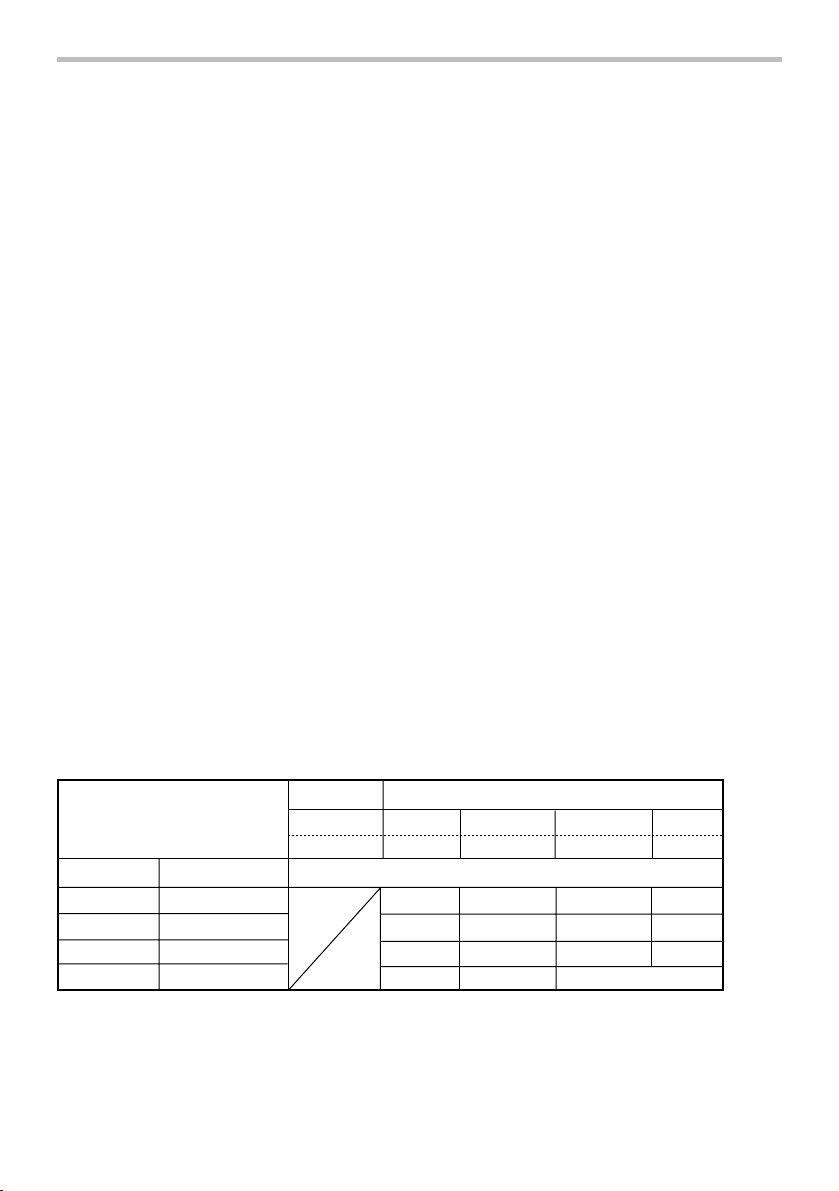
Depth adjustment
1
003557
The depth can be adjusted by turning the locking sleeve.
Turn it in "A" direction for less depth and in "B" direction
for more depth. One full turn of the locking sleeve
equals 1.5 mm (1/16") change in depth.
Adjust the locking sleeve so that the distance between
the tip of the locator and the screw head is
approximately 1 mm (3/64") as shown in the figure.
Drive a trial screw into your material or a piece of
duplicate material. If the depth is still not suitable for the
screw, continue adjusting until you obtain the proper
depth setting.
A
003558
003559
A
B
1
2
1
2
4
1. Locking sleeve
1. Approx. 1mm
(3/64")
2. Locator
1. Approx. 1mm
(3/64")
2. Locator
Page 5
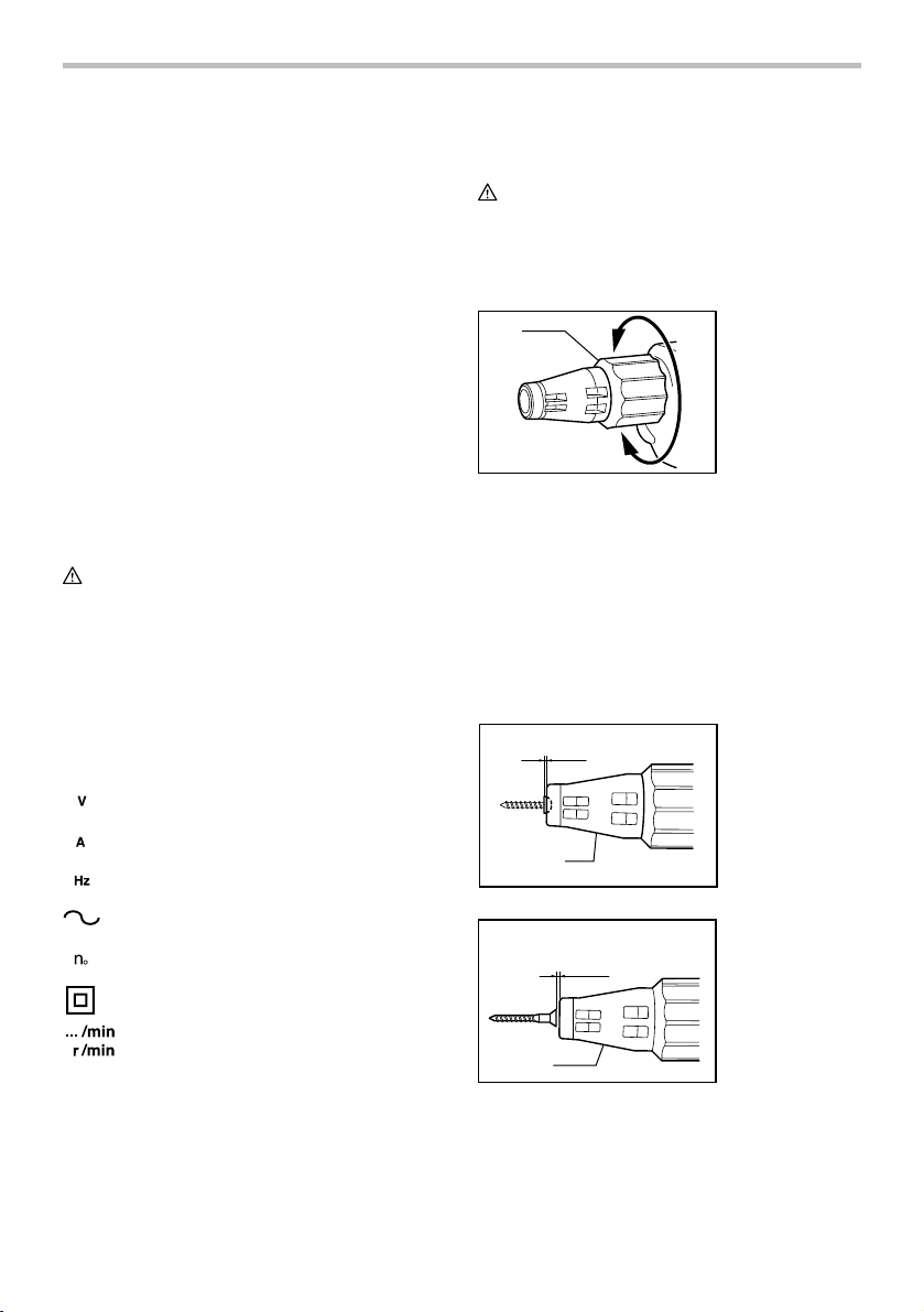
Switch action
1. Switch trigger
2. Lock button
1
2
003560
CAUTION:
• Before plugging in the tool, always check to see
that the switch trigger actuates properly and
returns to the "OFF" position when released.
To start the tool, simply pull the switch trigger. Tool
speed is increased by increasing pressure on the switch
trigger. Release the switch trigger to stop.
For continuous operation, pull the switch trigger and
then push in the lock button.
To stop the tool from the locked position, pull the switch
trigger fully, then release it.
NOTE:
• Even with the switch on and motor running, the bit
will not rotate until you fit the point of the bit in the
screw head and apply forward pressure to engage
the clutch.
Reversing switch action
1. Reversing
switch lever
AB
1
003561
This tool has a reversing switch to change the direction
of rotation. Move the reversing switch lever to
the
position (A side) for clockwise rotation or
the
position (B side) for counterclockwise rotation.
CAUTION:
• Always check the direction of rotation before
operation.
• Use the reversing switch only after the tool comes
to a complete stop. Changing the direction of
rotation before the tool stops may damage the tool.
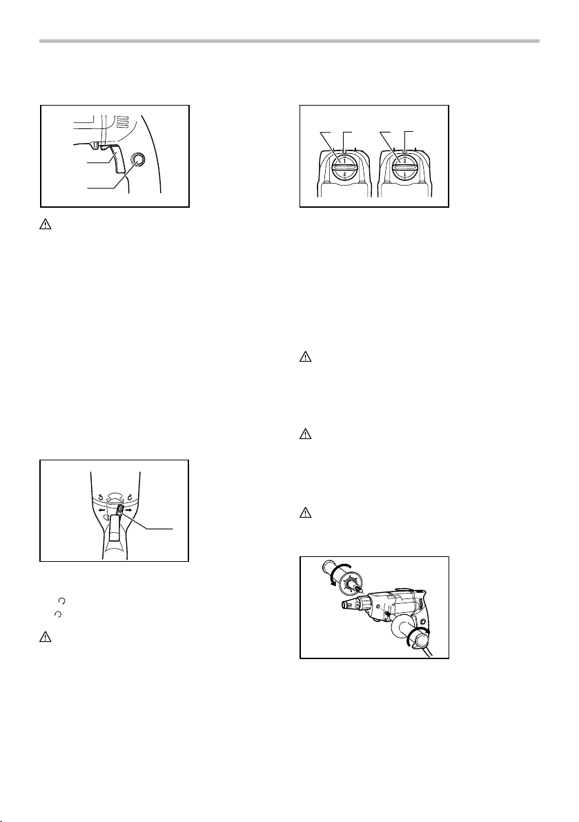
Speed change knob
1. Speed change
knob
2. Pointer
003562
12
12
Two rpm ranges can be preselected with the speed
change knob.
For low speed range (0 - 1,000 rpm), turn the knob so
that the pointer points to the number 1 marked on the
knob. (Fig.A)
For high speed range (0 - 2,200 rpm), turn the knob so
that the pointer points to the number 2. (Fig.B)
If it is hard to turn the knob, pull the switch trigger halfway for running the tool at low speed and turn the knob
again.
CAUTION:
• Do not turn the knob while the tool is running at full
speed. Malfunction of the tool may result.
ASSEMBLY
CAUTION:
• Always be sure that the tool is switched off and
unplugged before carrying out any work on the
tool.
Installing side grip (auxiliary handle)
CAUTION:
• Always be sure that the side grip is installed
securely before operation.
013573
Screw the side grip on the tool securely. The side grip
can be installed on either side of the tool, whichever is
convenient.
5
Page 6

Installing or removing the bit
1. Locator
2. Locking sleeve
12
003563
1
23
003564
To remove the bit, first pull the locator out of the locking
sleeve. Then grasp the bit with a pair of pliers and pull
the bit out of the magnetic bit holder. Sometimes, it
helps to wiggle the bit with the pliers as you pull.
To install the bit, push it firmly into the magnetic bit
holder. Then install the locator by pushing it firmly back
onto the locking sleeve.
1. Locator
2. Bit
3. Magnetic bit
holder
OPERATION
Fit the screw on the point of the bit and place the point
of the screw on the surface of the workpiece to be
fastened. Apply pressure to the tool and start it.
Withdraw the tool as soon as the clutch cuts in. Then
release the switch trigger.
CAUTION:
• When fitting the screw onto the point of the bit, be
careful not to push in on the screw. If the screw is
pushed in, the clutch will engage and the screw
will rotate suddenly. This could damage a
workpiece or cause an injury.
• Make sure that the bit is inserted straight in the
screw head, or the screw and/or bit may be
damaged.
MAINTENANCE
CAUTION:
• Always be sure that the tool is switched off and
unplugged before attempting to perform inspection
or maintenance.
• Never use gasoline, benzine, thinner, alcohol or
the like. Discoloration, deformation or cracks may
result.
To maintain product SAFETY and RELIABILITY, repairs,
carbon brush inspection and replacement, any other
maintenance or adjustment should be performed by
Makita Authorized or Factory Service Centers, always
using Makita replacement parts.
OPTIONAL ACCESSORIES
CAUTION:
• These accessories or attachments are
recommended for use with your Makita tool
specified in this manual. The use of any other
accessories or attachments might present a risk of
injury to persons. Only use accessory or
attachment for its stated purpose.
If you need any assistance for more details regarding
these accessories, ask your local Makita Service Center.
• Phillips bits
• Magnetic bit holder
• Magnetic socket bit
NOTE:
• Some items in the list may be included in the tool
package as standard accessories. They may differ
from country to country.
6
Page 7

MAKITA LIMITED ONE YEAR WARRANTY
Warranty Policy
Every Makita tool is thoroughly inspected and tested
before leaving the factory. It is warranted to be free of
defects from workmanship and materials for the period
of ONE YEAR from the date of original purchase.
Should any trouble develop during this one year period,
return the COMPLETE tool, freight prepaid, to one of
Makita’s Factory or Authorized Service Centers. If
inspection shows the trouble is caused by defective
workmanship or material, Makita will repair (or at our
option, replace) without charge.
This Warranty does not apply where:
repairs have been made or attempted by others:
repairs are required because of normal wear and
tear:
the tool has been abused, misused or improperly
maintained:
alterations have been made to the tool.
IN NO EVENT SHALL MAKITA BE LIABLE FOR ANY
INDIRECT, INCIDENTAL OR CONSEQUENTIAL
DAMAGES FROM THE SALE OR USE OF THE
PRODUCT. THIS DISCLAIMER APPLIES BOTH
DURING AND AFTER THE TERM OF THIS
WARRANTY.
MAKITA DISCLAIMS LIABILITY FOR ANY IMPLIED
WARRANTIES, INCLUDING IMPLIED WARRANTIES
OF "MERCHANTABILITY" AND "FITNESS FOR A
SPECIFIC PURPOSE," AFTER THE ONE YEAR TERM
OF THIS WARRANTY.
This Warranty gives you specific legal rights, and you
may also have other rights which vary from state to
state. Some states do not allow the exclusion or
limitation of incidental or consequential damages, so
the above limitation or exclusion may not apply to you.
Some states do not allow limitation on how long an
implied warranty lasts, so the above limitation may not
apply to you.
EN0006-1
7
Page 8

FRANÇAIS (Mode d’emploi original)
SPÉCIFICATIONS
Modèle 6807
Capacités
Vitesse à vide (T/MIN)
Longueur totale 318 mm (12-1/2")
Poids net 2,0 kg (4,4 lbs)
• Étant donné l'évolution constante de notre programme de recherche et de développement, les spécifications contenues dans ce
manuel sont sujettes à modification sans préavis.
• Les spécifications peuvent varier suivant les pays.
• Poids conforme à la procédure EPTA du 01/2003
Vis taraudeuse
Vis de plaque de plâtre
GEA008-2
Consignes de sécurité générales
pour outils électriques
MISE EN GARDE Veuillez lire toutes les mises
en garde de sécurité et toutes les instructions.
L'ignorance des mises en garde et des instructions
comporte un risque de choc électrique, d'incendie et/ou
de blessure grave.
Conservez toutes les mises en
garde et instructions pour
référence future.
Le terme ≪ outil électrique ≫ qui figure dans les
avertissements fait référence à un outil électrique
branché sur une prise de courant (par un cordon
d'alimentation) ou alimenté par batterie (sans fil).
Sécurité de la zone de travail
1. Maintenez la zone de travail propre et bien
éclairée. Les zones de travail encombrées ou
sombres ouvrent grande la porte aux accidents.
2. N'utilisez pas les outils électriques dans les
atmosphères explosives, par exemple en
présence de liquides, gaz ou poussières
inflammables. Les outils électriques produisent
des étincelles au contact desquelles la poussière
ou les vapeurs peuvent s'enflammer.
3. Assurez-vous qu'aucun enfant ou curieux ne
s'approche pendant que vous utilisez un outil
électrique. Vous risquez de perdre la maîtrise de
l'outil si votre attention est détournée.
Sécurité en matière d'électricité
4. Les fiches d'outil électrique sont conçues
pour s'adapter parfaitement aux prises de
courant. Ne modifiez jamais la fiche de
Grande 6 mm (1/4")
Bas 8 mm (5/16")
Grande 5 mm (3/16")
Bas 5 mm (3/16")
Grande 0 - 2 200 /min
Bas 0 - 1 000 /min
quelque façon que ce soit. N'utilisez aucun
adaptateur de fiche sur les outils électriques
avec mise à la terre. En ne modifiant pas les
fiches et en les insérant dans des prises de
courant pour lesquelles elles ont été conçues
vous réduirez les risques de choc électrique.
5. Évitez tout contact corporel avec les surfaces
mises à la terre, telles que les tuyaux,
radiateurs, cuisinières et réfrigérateurs. Le
risque de choc électrique est plus élevé si votre
corps se trouve mis à la terre.
6. N'exposez pas les outils électriques à la pluie
ou à l'eau. La présence d'eau dans un outil
électrique augmente le risque de choc électrique.
7. Ne maltraitez pas le cordon. N'utilisez jamais
le cordon pour transporter, tirer ou
débrancher l'outil électrique. Maintenez le
cordon à l'écart des sources de chaleur, de
l'huile, des objets à bords tranchants et des
pièces en mouvement. Le risque de choc
électrique est plus élevé lorsque les cordons sont
endommagés ou enchevêtrés.
8. Lorsque vous utilisez un outil électrique à
l'extérieur, utilisez un cordon prolongateur
prévu à cette fin. Les risques de choc électrique
sont moindres lorsqu'un cordon conçu pour
l'extérieur est utilisé.
9. Si vous devez utiliser un outil électrique dans
un endroit humide, utilisez une source
d'alimentation protégée par un disjoncteur de
fuite à la terre. L'utilisation d'un disjoncteur de
fuite à la terre réduit le risque de choc électrique.
Sécurité personnelle
10. Restez alerte, attentif à vos mouvements et
faites preuve de bon sens lorsque vous
utilisez un outil électrique. Évitez d'utiliser un
8
Page 9

outil électrique si vous êtes fatigué ou si vous
avez pris une drogue, de l'alcool ou un
médicament. Un moment d'inattention pendant
l'utilisation d'un outil électrique peut entraîner une
grave blessure.
11. Portez des dispositifs de protection
personnelle. Portez toujours un protecteur
pour la vue. Les risques de blessure seront
moins élevés si vous utilisez des dispositifs de
protection tels qu'un masque antipoussières, des
chaussures à semelle antidérapante, une coiffure
résistante ou une protection d'oreilles.
12. Évitez les démarrages accidentels. Assurez-
vous que l'interrupteur est en position d'arrêt
avant de brancher l'outil et/ou d'insérer la
batterie, ainsi qu'avant de saisir ou de
transporter l'outil. . Vous ouvrez la porte aux
accidents si vous transportez les outils
électriques avec le doigt sur l'interrupteur ou
laissez l'interrupteur en position de marche avant
de mettre l'outil sous tension.
13. Retirez toute clé de réglage ou de serrage
avant de mettre l'outil sous tension. Toute clé
laissée en place sur une pièce rotative de l'outil
électrique peut entraîner une blessure.
14. Maintenez une bonne position. Assurez-vous
d'une bonne prise au sol et d'une bonne
position d'équilibre en tout temps. Cela vous
permettra d'avoir une meilleure maîtrise de l'outil
dans les situations imprévues.
15. Portez des vêtements adéquats. Ne portez ni
vêtements amples ni bijoux. Vous devez
maintenir cheveux, vêtements et gants à
l'écart des pièces en mouvement. Les pièces
en mouvement peuvent happer les vêtements
amples, les bijoux et les cheveux longs.
16. Si des accessoires sont fournis pour
raccorder un appareil d'aspiration et de
collecte de la poussière, assurez-vous qu'ils
sont correctement raccordés et qu'ils sont
utilisés de manière adéquate. L'utilisation d'un
appareil d'aspiration permet de réduire les
risques liés à la présence de poussière dans l'air.
Utilisation et entretien des outils électriques
17. Ne forcez pas l'outil électrique. Utilisez l'outil
électrique adéquat suivant le type de travail à
effectuer. Si vous utilisez l'outil électrique
adéquat et respectez le régime pour lequel il a
été conçu, il effectuera un travail de meilleure
qualité et de façon plus sécuritaire.
18. N'utilisez pas l'outil électrique s'il n'est pas
possible de mettre sa gâchette en position de
marche et d'arrêt. Un outil électrique dont
l'interrupteur est défectueux représente un
danger et doit être réparé.
19. Débranchez la fiche de la source
d'alimentation et/ou retirez le bloc-piles de
l'outil électrique avant d'effectuer tout réglage,
de changer un accessoire ou de ranger l'outil
électrique. De telles mesures préventives
réduisent les risques de démarrage accidentel de
l'outil électrique.
20. Après l'utilisation d'un outil électrique,
rangez-le hors de portée des enfants et ne
laissez aucune personne l'utiliser si elle n'est
pas familiarisée avec l'outil électrique ou les
présentes instructions d'utilisation. Les outils
électriques représentent un danger entre les
mains de personnes qui n'en connaissent pas le
mode d'utilisation.
21. Veillez à l’entretien des outils électriques.
Assurez-vous que les pièces mobiles ne sont
pas désalignées ou coincées, qu’aucune
pièce n’est cassée et que l’outil électrique n’a
subi aucun dommage affectant son bon
fonctionnement. Le cas échéant, faites
réparer l'outil électrique avant de l'utiliser. De
nombreux accidents sont causés par des outils
électriques mal entretenus.
22. Maintenez les outils tranchants bien aiguisés
et propres. Un outil tranchant dont l'entretien est
effectué correctement et dont les bords sont bien
aiguisés risquera moins de se coincer et sera
plus facile à maîtriser.
23. Utilisez l'outil électrique, ses accessoires, ses
embouts, etc., en respectant les présentes
instructions, en tenant compte des conditions
de travail et du type de travail à effectuer.
L'utilisation d'un outil électrique à des fins autres
que celles prévues peut entraîner une situation
dangereuse.
Réparation
24. Faites réparer votre outil électrique par un
réparateur qualifié qui utilise des pièces de
rechange identiques aux pièces d'origine. Le
maintien de la sûreté de l'outil électrique sera
ainsi assuré.
25. Suivez les instructions de lubrification et de
changement des accessoires.
26. Maintenez les poignées de l'outil sèches,
propres et exemptes d'huile ou de graisse.
UTILISEZ UN CORDON PROLONGATEUR
APPROPRIÉ. Assurez-vous que votre cordon
prolongateur est en bonne condition. Lorsque vous
utilisez un cordon prolongateur, assurez-vous qu'il est
assez robuste pour transporter le courant exigé par le
produit. Un cordon qui est trop petit entraînera une
baisse dans la tension composée, ce qui causera une
perte d'énergie et un surchauffage. Le tableau 1 indique
la dimension de cordon à utiliser, en fonction de la
9
Page 10

longueur du cordon et de l'intensité nominale figurant
sur la plaque signalétique. En cas de doute, utilisez un
cordon plus robuste. Plus le numéro de calibre est bas,
plus le cordon est robuste.
Tableau 1. Gabarit minimum du cordon
Vol ts
Intensité nominale
120V 25 pi 50 pi 100 pi 150 pi
220V - 240V 50 pi 100 pi 200 pi 300 pi
Plus de Pas plus de
06
6
10
12
000300
10
12
16
GEB017-4
CONSIGNES DE SÉCURITÉ
POUR LE TOURNEVIS
1. Tenez l'outil électrique par les surfaces de
prise isolées lorsque vous réalisez une
manoeuvre où la pièce de fixation risque
d'entrer en contact avec des câblages cachés
ou avec son propre cordon. Les pièces de
fixation entrant en contact avec un fil sous
tension pourraient transmettre le courant aux
pièces métalliques exposées de l'outil et procurer
un choc électrique à l'utilisateur.
2. Adoptez toujours une position de travail vous
assurant d'un bon équilibre.
Assurez-vous qu'il n'y a personne plus bas
lorsque vous utilisez l'outil en position élevée.
3. Tenez l'outil fermement.
4.
Gardez les mains éloignées des pièces en rotation.
5. Ne touchez ni la fraise, ni la pièce à travailler
immédiatement après l'utilisation ; elles
peuvent être extrêmement chaudes et vous
pourriez vous brûler la peau.
CONSERVEZ CE MODE
D'EMPLOI.
AVERTISSEMENT:
NE VOUS LAISSEZ PAS tromper (au fil d'une
utilisation répétée) par un sentiment d'aisance ou
de familiarité avec le produit en négligeant les
consignes de sécurité qui accompagnent le produit.
L'utilisation non sécuritaire ou incorrecte de cet
outil comporte un risque de blessure grave.
Longueur totale du cordon en pieds
Calibre américain des fils
18
18
16
14
16 16 14
1416
16
12
14
Non recommandé
12
12
Symboles
Les symboles utilisés pour l'outil sont indiqués cidessous.
・ volts
・ ampères
・ hertz
・ courant alternatif
・ vitesse à vide
・ construction, catégorie II
・ tours ou alternances par minute
10
USD201-2
Page 11

DESCRIPTION DU
FONCTIONNEMENT
ATT EN TI ON :
• Assurez-vous toujours que l'outil est hors tension
et débranché avant de l'ajuster ou de vérifier son
fonctionnement.
Réglage de la profondeur
1
003557
Réglez la profondeur en tournant le manchon de
verrouillage. Tournez-le dans le sens "A" pour réduire la
profondeur, et dans le sens "B" pour augmenter la
profondeur. Un tour complet du manchon de
verrouillage représente un changement de profondeur
de 1.5 mm (1/16").
Réglez le manchon de verrouillage de façon que la
distance entre l'extrémité du positionneur et la tête de
vis soit d'environ 1 mm (3/64"), comme indiqué à les
figures. Enfoncez une vis d'essai dans la pièce ou dans
un morceau de matériau similaire. Si la profondeur ne
convient toujours pas pour la vis, continuez à régler
jusqu'à ce que vous obteniez le réglage de profondeur
voulu.
A
B
1. Manchon de
verrouillage
Interrupteur
1. Gâchette
2. Bouton de
verrouillage
1
2
003560
ATT EN TI ON :
• Avant de brancher l'outil, assurez-vous toujours
que la gâchette fonctionne correctement et revient
en position d'arrêt une fois relâchée.
Pour mettre l'outil en marche, appuyez simplement sur
la gâchette. La vitesse de l'outil augmente à mesure
que l'on accroît la pression exercée sur la gâchette.
Pour l'arrêter, relâchez la gâchette.
Pour un fonctionnement continu, appuyez sur la
gâchette puis enfoncez le bouton de verrouillage.
Pour arrêter l'outil alors qu'il est en position verrouillée,
appuyez à fond sur la gâchette puis relâchez-la.
NOTE:
• Même si l'interrupteur est enclenché et que le
moteur tourne, l'embout ne tournera pas tant que
vous n'aurez pas inséré la pointe de l'embout dans
la tête de vis et que vous n'exercerez pas de
pression vers l'avant pour engager l'embrayage.
Inverseur
1. Levier inverseur
A
003558
003559
1. Environ 1 mm
1
2
1
2
(3/64")
2. Positionneur
003561
1. Environ 1 mm
(3/64")
2. Positionneur
L'outil possède un inverseur qui permet de changer le sens
de rotation. Déplacez le levier inverseur sur la position
(côté A) pour une rotation dans le sens des aiguilles d'une
montre, ou sur la position
dans le sens inverse des aiguilles d'une montre.
• Vérifiez toujours le sens de rotation avant de
• N'actionnez l'inverseur qu'une fois que l'outil est
11
AB
ATT EN TI ON :
mettre l'outil en marche.
complètement arrêté. Si vous changez le sens de
rotation avant l'arrêt de l'outil, vous risquez de
l'endommager.
1
(côté B) pour une rotation
Page 12

Bouton de changement de vitesse
1. Bouton de
12
003562
Le bouton de changement de vitesse permet de
prérégler l'outil sur l'une ou l'autre de deux plages de
vitesse (t/min).
Pour sélectionner la plage de vitesse réduite (0 à 1,000
t/min), tournez le bouton de façon que le pointeur
indique le numéro 1 inscrit sur le bouton. (Fig. A)
Pour sélectionner la plage de vitesse élevée (0 à 2,200
t/min), tournez le bouton de façon que le pointeur
indique le numéro 2 inscrit sur le bouton. (Fig. B)
Si le bouton est difficile à tourner, enfoncez la gâchette
à moitié pour faire fonctionner l'outil à vitesse réduite
puis tournez le bouton.
ATT EN TI ON :
• Ne tournez jamais le bouton pendant que l'outil
fonctionne à pleine vitesse. Cela risquerait
d'endommager l'outil.
12
changement de
vitesse
2. Index
ASSEMBLAGE
ATT EN TI ON :
• Avant d'effectuer toute intervention sur l'outil,
assurez-vous toujours qu'il est hors tension et
débranché.
Installation de la poignée latérale (poignée
auxiliaire)
ATT EN TI ON :
• Avant d'utiliser l'outil, assurez-vous toujours que la
poignée latérale est installée de façon sûre.
Installation et retrait du embout
1. Positionneur
2. Manchon de
verrouillage
12
003563
1
23
003564
Pour retirer l'embout, retirez d'abord le positionneur du
manchon de verrouillage en tirant. Saisissez ensuite
l'embout avec une paire de pinces et dégagez l'embout
du porte-embout magnétique. L'embout est parfois plus
facile à retirer si on le fait bouger avec les pinces tout
en tirant.
Pour installer l'embout, enfoncez-le à fond dans le
porte-embout magnétique. Puis, remontez le
positionneur en le poussant à fond contre le manchon
de verrouillage.
1. Positionneur
2. Embout
3. Porte-embout
magnétique
UTILISATION
Mettez la vis en place sur l'extrémité de l'embout et
placez cette dernière sur la surface de la pièce à visser.
Appliquez une pression sur l'outil et mettez le contact.
Retirez l'outil aussitôt que l'embrayage s'active, puis
relâchez la gâchette.
ATT EN TI ON :
• Lorsque vous mettez la vis en place sur l'extrémité
de l'embout, prenez garde de pousser ce dernier
dans la vis. Si l'embout est poussé dans la vis,
l'embrayage s'engagera et la vis se mettra
soudainement à tourner. Vous risquez alors
d'endommager la pièce ou de vous blesser.
• Assurez-vous que l'embout est inséré bien droit
dans la tête de vis, sinon la vis et/ou l'embout
risque d'être endommagé.
013573
Vissez la poignée latérale à fond sur l'outil. La poignée
latérale peut être installée d'un côté ou de l'autre de
l'outil en fonction du travail à effectuer.
12
Page 13

ENTRETIEN
A
À
A
ATT EN TI ON :
• Assurez-vous toujours que l'outil est hors tension
et débranché avant d'y effectuer tout travail
d'inspection ou d'entretien.
• N'utilisez jamais d'essence, de benzine, de solvant,
d'alcool ou d'autres produits similaires. Une
décoloration, une déformation, ou la formation de
fissures peuvent en découler.
Pour maintenir la SÉCURITÉ et la FIABILITÉ du produit,
les réparations, l'inspection et le remplacement des
charbons, et tout autre travail d'entretien ou de réglage
doivent être effectués dans une usine ou un centre de
service après-vente Makita agréé, exclusivement avec
des pièces de rechange Makita.
ACCESSOIRES EN OPTION
ATT EN TI ON :
• Ces accessoires ou pièces complémentaires sont
recommandés pour l'utilisation avec l'outil Makita
spécifié dans ce mode d'emploi. L'utilisation de
tout autre accessoire ou pièce complémentaire
peut comporter un risque de blessure. N'utilisez
les accessoires ou pièces qu'aux fins auxquelles
ils ont été conçus.
Si vous désirez obtenir plus de détails concernant ces
accessoires, veuillez contacter le centre de service
après-vente Makita le plus près.
• Embouts Phillips
• Porte-embout magnétique
• Embout à douille magnétique
NOTE:
• Certains éléments de la liste peuvent être inclus
avec l'outil comme accessoires standard. Ils
peuvent varier suivant les pays.
GARANTIE LIMITÉE D’UN AN MAKITA
Politique de garantie
Chaque outil Makita est inspecté rigoureusement et
testé avant sa sortie d’usine. Nous garantissons qu’il
sera exempt de défaut de fabrication et de vice de
matériau pour une période d’UN AN à partir de la date
de son achat initial. Si un problème quelconque devait
survenir au cours de cette période d’un an, veuillez
retourner l’outil COMPLET, port payé, à une usine ou à
un centre de service après-vente Makita. Makita
réparera l’outil gratuitement (ou le remplacera, à sa
discrétion) si un défaut de fabrication ou un vice de
matériau est découvert lors de l’inspection.
Cette garantie ne s’applique pas dans les cas où:
des réparations ont été effectuées ou tentées par
un tiers:
des réparations s’imposent suite à une usure
normale:
l’outil a été malmené, mal utilisé ou mal entretenu:
l’outil a subi des modifications.
MAKITA DÉCLINE TOUTE RESPONSABILITÉ POUR
TOUT DOMMAGE ACCESSOIRE OU INDIRECT LIÉ À
LA VENTE OU À L’UTILISATION DU PRODUIT. CET
VIS DE NON-RESPONSABILITÉ S’APPLIQUE À LA
FOIS PENDANT ET APRÈS LA PÉRIODE COUVERTE
PAR CETTE GARANTIE.
MAKITA DÉCLINE TOUTE RESPONSABILITÉ QUANT
TOUTE GARANTIE TACITE, INCLUANT LES
GARANTIES TACITES DE “QUALITÉ MARCHANDE”
ET “ADÉQUATION À UN USAGE PARTICULIER”
PRÈS LA PÉRIODE D’UN AN COUVERTE PAR
CETTE GARANTIE.
Cette garantie vous donne des droits spécifiques
reconnus par la loi, et possiblement d’autres droits, qui
varient d’un État à l’autre. Certains États ne permettant
pas l’exclusion ou la limitation des dommages
accessoires ou indirects, il se peut que la limitation ou
exclusion ci-dessus ne s’applique pas à vous. Certains
États ne permettant pas la limitation de la durée
d’application d’une garantie tacite, il se peut que la
limitation ci-dessus ne s’applique pas à vous.
EN0006-1
13
Page 14

ESPAÑOL (Instrucciones originales)
ESPECIFICACIONES
Modelo 6807
Capacidades
Velocidad sin carga (r.p.m.)
• Debido a nuestro programa continuo de investigación y desarrollo, las especificaciones aquí dadas están sujetas a cambios sin
previo aviso.
• Las especificaciones pueden ser diferentes de país a país.
• Peso de acuerdo al procedimiento de EPTA-01/2003
Advertencias de seguridad
Tornillo de autoperforación
Tornillo para pared
"sheetrock"
Longitud total 318 mm (12-1/2")
Peso neto 2,0 kg (4,4 lbs)
GEA008-2
Seguridad eléctrica
4. Las clavijas de conexión de las herramientas
generales para herramientas
eléctricas
ADVERTENCIA: lea todas las advertencias de
seguridad e instrucciones. Si no sigue todas las
advertencias e instrucciones indicadas a continuación,
podrá ocasionar una descarga eléctrica, un incendio y/o
lesiones graves.
Guarde todas las advertencias e
5. Evite tocar con el cuerpo superficies
instrucciones para su futura
referencia.
El término "herramienta eléctrica" se refiere, en todas
las advertencias que aparecen a continuación, a su
herramienta eléctrica de funcionamiento con conexión a
la red eléctrica (con cableado eléctrico) o herramienta
eléctrica de funcionamiento a batería (inalámbrica).
Seguridad en el área de trabajo
1. Mantenga el área de trabajo limpia y bien
iluminada. Las áreas oscuras o desordenadas
son propensas a accidentes.
2. No utilice las herramientas eléctricas en
atmósferas explosivas, tal como en la
presencia de líquidos, gases o polvo
inflamables. Las herramientas eléctricas crean
chispas que pueden prender fuego al polvo o los
humos.
3. Mantenga a los niños y curiosos alejados
mientras utiliza una herramienta eléctrica. Las
distracciones le pueden hacer perder el control.
6. No exponga las herramientas eléctricas a la
7. No jale el cable. Nunca utilice el cable para
8. Cuando utilice una herramienta eléctrica en
14
Alta 6 mm (1/4")
Baja 8 mm (5/16")
Alta 5 mm (3/16")
Baja 5 mm (3/16")
Alta 0 - 2 200 r/min
Baja 0 - 1 000 r/min
eléctricas deberán encajar perfectamente en
la toma de corriente. No modifique nunca la
clavija de conexión de ninguna forma. No
utilice ninguna clavija adaptadora con
herramientas eléctricas que tengan conexión
a tierra (puesta a tierra). La utilización de
clavijas no modificadas y que encajen
perfectamente en la toma de corriente reducirá el
riesgo de que se produzca una descarga
eléctrica.
conectadas a tierra o puestas a tierra tales
como tubos, radiadores, cocinas y
refrigeradores. Si su cuerpo es puesto a tierra o
conectado a tierra existirá un mayor riesgo de
que sufra una descarga eléctrica.
lluvia ni a condiciones húmedas. La entrada de
agua en una herramienta eléctrica aumentará el
riesgo de que se produzca una descarga
eléctrica.
transportar, jalar o desconectar la herramienta
eléctrica. Mantenga el cable alejado del calor,
aceite, objetos cortantes o piezas móviles.
Los cables dañados o atrapados aumentan el
riesgo de sufrir una descarga eléctrica.
exteriores, utilice un cable de extensión
apropiado para uso en exteriores. La
utilización de un cable apropiado para uso en
exteriores reducirá el riesgo de que se produzca
una descarga eléctrica.
Page 15

9. Si no es posible evitar usar una herramienta
eléctrica en condiciones húmedas, utilice un
alimentador protegido con interruptor de
circuito de falla en tierra (ICFT). El uso de un
ICFT reduce el riesgo de descarga eléctrica.
Seguridad personal
10. Manténgase alerta, preste atención a lo que
está haciendo y utilice su sentido común
cuando opere una herramienta eléctrica. No
utilice la herramienta eléctrica cuando esté
cansado o bajo la influencia de drogas,
alcohol o medicamentos. Un momento de
distracción mientras opera la máquina puede dar
como resultado heridas personales graves.
11. Use equipo de protección personal. Póngase
siempre protección para los ojos. El equipo
protector tal como máscara contra el polvo,
zapatos de seguridad antiderrapantes, casco
rígido y protección para oídos utilizado en las
condiciones apropiadas reducirá las heridas
personales.
12. Impida el encendido accidental. Asegúrese de
que el interruptor esté en la posición de
apagado antes de conectar a la alimentación
eléctrica y/o de colocar el cartucho de la
batería, así como al levantar o cargar la
herramienta. Cargar las herramientas eléctricas
con su dedo en el interruptor o conectarlas con el
interruptor encendido hace que los accidentes
sean propensos.
13. Retire cualquier llave de ajuste o llave de
apriete antes de encender la herramienta. Una
llave de ajuste o llave de apriete que haya sido
dejada puesta en una parte giratoria de la
herramienta eléctrica podrá resultar en heridas
personales.
14. No utilice la herramienta donde no alcance.
Mantenga los pies sobre suelo firme y el
equilibrio en todo momento. Esto permite un
mejor control de la herramienta eléctrica en
situaciones inesperadas.
15. Use vestimenta apropiada. No use ropas
sueltas ni joyas. Mantenga el cabello, la ropa
y los guantes alejados de las partes móviles,
ya que pueden ser atrapadas por estas partes en
movimiento.
16. Si dispone de dispositivos para la conexión
de equipos de extracción y recolección de
polvo, asegúrese de conectarlos y utilizarlos
debidamente. La utilización de estos dispositivos
reduce los riesgos relacionados con el polvo.
Mantenimiento y uso de la herramienta eléctrica
17. No fuerce la herramienta eléctrica. Utilice la
herramienta eléctrica correcta para su
aplicación. La herramienta eléctrica adecuada
hará un trabajo mejor a la velocidad para la que
ha sido fabricada.
18. No utilice la herramienta eléctrica si el
interruptor no la enciende y apaga. Cualquier
herramienta eléctrica que no pueda ser
controlada con el interruptor es peligrosa y debe
ser reemplazada.
19. Desconecte la clavija de la fuente de energía
y/o la batería de la herramienta eléctrica antes
de realizar ajustes, cambiar accesorios o
guardar las herramientas eléctricas. Dichas
medidas de seguridad preventivas reducen el
riesgo de que la herramienta se inicie
accidentalmente.
20. Guarde la herramienta eléctrica que no use
fuera del alcance de los niños y no permita
que las personas que no están familiarizadas
con ella o con las instrucciones la operen. Las
herramientas eléctricas son peligrosas en manos
de personas que no saben operarlas
21. Realice el mantenimiento a las herramientas
eléctricas. Compruebe que no haya partes
móviles desalineadas o estancadas, piezas
rotas y cualquier otra condición que pueda
afectar al funcionamiento de la herramienta
eléctrica. Si la herramienta eléctrica está
dañada, haga que se la reparen antes de
utilizarla. Muchos accidentes son ocasionados
por herramientas eléctricas con un mal
mantenimiento.
22. Mantenga las herramientas de corte limpias y
filosas. Si recibe un mantenimiento adecuado y
tiene los bordes afilados, es probable que la
herramienta se atasque menos y sea más fácil
controlarla.
23. Utilice la herramienta eléctrica, así como
accesorios, piezas, brocas, etc. de acuerdo
con estas instrucciones y de la manera
establecida para cada tipo de unidad en
particular; tenga en cuenta las condiciones
laborales y el trabajo a realizar. Si utiliza la
herramienta eléctrica para realizar operaciones
distintas de las indicadas, podrá presentarse una
situación peligrosa.
Servicio de mantenimiento
24. Haga que una persona calificada repare la
herramienta utilizando sólo piezas de
repuesto idénticas. Esto asegura que se
mantenga la seguridad de la herramienta
eléctrica.
25. Siga las instrucciones para la lubricación y
cambio de accesorios.
26. Mantenga las agarraderas secas, limpias y sin
aceite o grasa.
15
Page 16

UTILICE CABLES DE EXTENSIÓN APROPIADOS.
Asegúrese de que su cable de extensión esté en
buenas condiciones. Cuando utilice un cable de
extensión, asegúrese de utilizar uno del calibre
suficiente para conducir la corriente que demande el
producto. Un cable de calibre inferior ocasionará una
caída en la tensión de línea y a su vez en una pérdida
Tabla 1. Calibre mínimo para el cable
de potencia y sobrecalentamiento. La Tabla 1 muestra
la medida correcta a utilizar dependiendo de la longitud
del cable y el amperaje nominal indicado en la placa de
características. Si no está seguro, utilice el siguiente
calibre más alto. Cuanto menor sea el número de
calibre, más corriente podrá conducir el cable.
Vol ts
Amperaje nominal
Más de No más de
0 A 6 A
6 A
10 A
12 A
000300
120V~
220V~ - 240V~15,2 m (50 ft) 30,4 m (100 ft) 60,8 m (200 ft) 91,2 m (300 ft)
10 A
12 A
16 A
7,6 m (25 ft) 15,2 m (50 ft) 30,4 m (100 ft) 45,7 m (150 ft)
GEB017-4
ADVERTENCIAS DE SEGURIDAD
DEL DESTORNILLADOR
1. Sujete la herramienta eléctrica por las
superficies de agarre aisladas al realizar una
operación en la que el sujetador pueda entrar
en contacto con cables ocultos o con su
propio cable. Si el sujetador entra en contacto
con un cable con corriente, las piezas metálicas
expuestas de la herramienta eléctrica se
cargarán también de corriente y el operario
puede recibir una descarga.
2. Asegúrese siempre de que pisa sobre suelo
firme.
Asegúrese de que no haya nadie debajo
cuando utilice la herramienta en lugares altos.
3. Sostenga la herramienta con firmeza.
4. Mantenga las manos alejadas de las piezas
giratorias.
5. No toque la broca o la pieza de trabajo
inmediatamente después de utilizarla; podrían
estar muy calientes y producirle quemaduras
de piel.
GUARDE ESTAS
INSTRUCCIONES.
Longitud total del cable en metros
Calibre del cable (AWG)
18
18
16
14
16 16 14
1416
16
12
14
No se recomienda
12
12
ADVERTENCIA:
NO DEJE que la comodidad o familiaridad con el
producto (a base de utilizarlo repetidamente)
sustituya la estricta observancia de las normas de
seguridad para dicho producto. El MAL USO o el no
seguir las normas de seguridad establecidas en
este manual de instrucciones puede ocasionar
graves lesiones personales.
Símbolos
A continuación se muestran los símbolos utilizados para
la herramienta.
・ volts o voltios
・ amperes
・ hertz
・ corriente alterna
・ velocidad en vacío o sin carga
・ Construcción clase II
・ revoluciones o alternaciones por
minuto, frecuencia de rotación.
16
USD201-2
Page 17

DESCRIPCIÓN DEL
FUNCIONAMIENTO
PRECAUCIÓN:
• Asegúrese siempre de que la herramienta esté
apagada y desconectada antes de ajustar o
comprobar cualquier función en la misma.
Ajuste de la profundidad
1
003557
La profundidad puede ajustarse al girar la funda de
bloqueo. Gírela a la dirección "A" para menor
profundidad, y hacia la dirección "B" para mayor
profundidad. Un giro completo en la funda de bloqueo
equivale a un cambio de 1,5 mm (1/16") en la
profundidad.
Ajuste la funda de bloqueo de tal manera que la
distancia entre la punta del localizador y la cabeza del
tornillo sea aproximadamente de 1 mm (3/64") como se
muestra en la ilustración. Coloque un tornillo de prueba
en su material o pieza de réplica del material. Si la
profundidad no corresponde con el tornillo, continúe
ajustando hasta que obtenga la configuración de
profundidad apropiada.
A
003558
003559
A
B
1
2
1
2
1. Funda de
bloqueo
1. Aprox. 1mm
(3/64")
2. Localizador
1. Aprox. 1mm
(3/64")
2. Localizador
Accionamiento del interruptor
1. Gatillo
interruptor
2. Botón de
bloqueo
1
2
003560
PRECAUCIÓN:
• Antes de conectar la herramienta, compruebe
siempre que el gatillo interruptor se acciona
debidamente y que vuelve a la posición "OFF"
(apagado) cuando lo suelta.
Para poner en marcha la herramienta, simplemente
apriete el gatillo. La velocidad de la herramienta
incrementa aumentando la presión en el gatillo. Suelte
el gatillo para parar.
Para una operación continua, apriete el gatillo y
después meta el botón de bloqueo.
Para detener la herramienta estando en la posición
bloqueada, apriete completamente el gatillo y luego
suéltelo.
NOTA:
• Incluso con el interruptor en la posición de
encendido y el motor corriendo, la punta no rotará
hasta que se encaje la punta de atornillar en la
cabeza del tornillo y aplique presión a favor para
enganchar el embrague (clutch).
Accionamiento del conmutador de inversión
de giro
Palanca del
1.
conmutador de
inversión de giro
AB
1
003561
Esta herramienta cuenta con un conmutador de
inversión de giro para cambiar la dirección de rotación.
Mueva la palanca del conmutador de inversión hacia la
posición
la posición
• Confirme siempre la dirección de giro antes de la
17
(lado A) para girar hacia la derecha o hacia
(lado B) para girar hacia a la izquierda.
PRECAUCIÓN:
operación.
Page 18

• Utilice el conmutador de inversión solamente
después de que la herramienta haya parado
completamente. Si cambia la dirección de giro
antes de que la herramienta haya parado podrá
dañarla.
Perilla de cambio de velocidad
1. Perilla de
12
003562
Es posible seleccionar dos rangos predeterminados de
revoluciones por minuto (rpm) con la perilla de cambio
de velocidad.
Para el rango de velocidad menor (0 – 1 000 rpm), gire
la perilla de tal forma que el apuntador señale al
número 1 marcado en la perilla (Fig.A).
Para el rango de velocidad mayor (0 - 2 200 rpm), gire
la perilla de tal forma que el apuntador señale el
número 2 (Fig.B).
En caso de que se dificulte girar la perilla, jale a
medias el gatillo interruptor hacia la posición de
velocidad baja y vuelva a girar la perilla.
PRECAUCIÓN:
• No gire la perilla mientras la herramienta se
encuentre corriendo a velocidad completa. Esto
podría ocasionar defectos en el funcionamiento.
12
cambio de
velocidad
2. Apuntador o
puntero
ENSAMBLE
PRECAUCIÓN:
• Asegúrese siempre de que la herramienta esté
apagada y desconectada antes de realizar
cualquier trabajo en la misma.
Instalación de la empuñadura lateral (mango
auxiliar)
PRECAUCIÓN:
• Antes de realizar una operación, asegúrese
siempre de que la empuñadura lateral esté
instalada firmemente.
013573
Atornille firmemente la empuñadura lateral a la
herramienta. La empuñadura lateral se puede instalar
en cualquier lado de la herramienta, el que sea
conveniente.
Instalación o extracción de la punta.
1. Localizador
2. Funda de
bloqueo
12
003563
1
23
003564
Para quitar la broca, primero saque el localizador de la
funda de bloqueo. Luego sujete la broca con un par de
tenazas y jale para sacarla del portabrocas magnético.
A veces, resulta útil contonear la broca con las tenazas
a medida que la saca.
Para instalar la broca, empújela firmemente en el
portabrocas magnético. Luego instale el localizador al
empujarlo firmemente de regreso en el estuche de
bloqueo.
1. Localizador
2. Punta de
atornillar
3. Portapuntas
magnético
18
Page 19

OPERACIÓN
Encaje la punta de atornillar sobre la cabeza del tornillo
y la punta del tornillo en la superficie de la pieza de
trabajo a ser fijada. Aplique presión a la herramienta y
enciéndala. Retire la herramienta tan pronto el
embrague (clutch) se accione. Luego suelte el gatillo
del interruptor.
PRECAUCIÓN:
• Cuando encaje la punta sobre la cabeza del
tornillo, tenga cuidado de no empujar el tornillo. Si
el tornillo se empuja hacia adentro, el embrague
se engranará y el tornillo rotará repentinamente.
Esto podría dañar la pieza de trabajo o causar una
lesión.
• Asegúrese de que la punta está insertada
rectamente en la cabeza del tornillo, o el tornillo
y/o la punta podrían dañarse.
MANTENIMIENTO
PRECAUCIÓN:
• Asegúrese siempre que la herramienta esté
apagada y desconectada antes de intentar realizar
una inspección o mantenimiento.
• Nunca use gasolina, bencina, diluyente (tíner),
alcohol o sustancias similares. Puede que esto
ocasione grietas o descoloramiento.
Para mantener la SEGURIDAD y FIABILIDAD del
producto, las reparaciones, la inspección y sustitución
de las escobillas de carbón, y cualquier otro
mantenimiento o ajuste deberán ser realizados en
Centros o Servicios de fábrica Autorizados por Makita,
empleando siempre piezas de repuesto de Makita.
ACCESORIOS OPCIONALES
PRECAUCIÓN:
• Estos accesorios o aditamentos (incluidos o no)
están recomendados para utilizar con su
herramienta Makita especificada en este manual.
El empleo de cualesquiera otros accesorios o
acoplamientos conllevará un riesgo de sufrir
heridas personales. Utilice los accesorios o
acoplamientos solamente para su fin establecido.
Si necesita cualquier ayuda para más detalles en
relación con estos accesorios, pregunte a su centro de
servicio Makita local.
• Brocas phillips
• Portapuntas magnético
• Broca de entrada magnética
NOTA:
• Algunos de los artículos en la lista puede que
vengan junto con el paquete de la herramienta
como accesorios incluidos. Puede que estos
accesorios varíen de país a país.
GARANTÍA LIMITADA MAKITA DE UN AÑO
Ésta Garantía no aplica para México
Política de garantía
Cada herramienta Makita es inspeccionada y probada
exhaustivamente antes de salir de fábrica. Se
garantiza que va a estar libre de defectos de mano de
obra y materiales por el periodo de UN AÑO a partir de
la fecha de adquisición original. Si durante este
periodo de un año se desarrollase algún problema,
retorne la herramienta COMPLETA, porte pagado con
antelación, a una de las fábricas o centros de servicio
autorizados Makita. Si la inspección muestra que el
problema ha sido causado por mano de obra o
material defectuoso, Makita la reparará (o a nuestra
opción, reemplazará) sin cobrar.
Esta garantía no será aplicable cuando:
se hayan hecho o intentado hacer reparaciones
por otros:
se requieran reparaciones debido al desgaste
normal:
la herramienta haya sido abusada, mal usada o
mantenido indebidamente:
se hayan hecho alteraciones a la herramienta.
EN NINGÚN CASO MAKITA SE HARÁ
RESPONSABLE DE NINGÚN DAÑO INDIRECTO,
FORTUITO O CONSECUENCIAL DERIVADO DE LA
VENTA O USO DEL PRODUCTO.
ESTA RENUNCIA SERÁ APLICABLE TANTO
DURANTE COMO DESPUÉS DEL TÉRMINO DE
ESTA GARANTÍA.
MAKITA RENUNCIA LA RESPONSABILIDAD POR
CUALQUIER GARANTÍA IMPLÍCITA, INCLUYENDO
GARANTÍAS IMPLÍCITAS DE “COMERCIALIDAD” E
“IDONEIDAD PARA UN FIN ESPECÍFICO”, DESPUÉS
DEL TÉRMINO DE UN AÑO DE ESTA GARANTÍA.
Esta garantía le concede a usted derechos legales
específicos, y usted podrá tener también otros
derechos que varían de un estado a otro. Algunos
estados no permiten la exclusión o limitación de daños
fortuitos o consecuenciales, por lo que es posible que
la antedicha limitación o exclusión no le sea de
aplicación a usted. Algunos estados no permiten
limitación sobre la duración de una garantía implícita,
por lo que es posible que la antedicha limitación no le
sea de aplicación a usted.
EN0006-1
19
Page 20

< USA only >
WARNING
Some dust created by power sanding, sawing, grinding, drilling, and other
construction activities contains chemicals known to the State of California
to cause cancer, birth defects or other reproductive harm. Some examples
of these chemicals are:
• lead from lead-based paints,
• crystalline silica from bricks and cement and other masonry products, and
• arsenic and chromium from chemically-treated lumber.
Your risk from these exposures varies, depending on how often you do this
type of work. To reduce your exposure to these chemicals: work in a well
ventilated area, and work with approved safety equipment, such as those
dust masks that are specially designed to filter out microscopic particles.
< USA solamente >
ADVERTENCIA
Algunos tipos de polvo creados por el lijado, serrado, amolado, taladrado, y
otras actividades de la construccion contienen sustancias quimicas
reconocidas por el Estado de California como causantes de cancer, defectos
de nacimiento y otros peligros de reproduccion. Algunos ejemplos de estos
productos quimicos son:
• plomo de pinturas a base de plomo,
• silice cristalino de ladrillos y cemento y otros productos de albanileria, y
• arsenico y cromo de maderas tratadas quimicamente.
El riesgo al que se expone variara, dependiendo de la frecuencia con la que
realice este tipo de trabajo. Para reducir la exposicion a estos productos
quimicos: trabaje en un area bien ventilada, y pongase el equipo de seguridad
indicado, tal como esas mascaras contra el polvo que estan especialmente
disenadas para filtrar particulas microscopicas.
Makita Corporation
3-11-8, Sumiyoshi-cho,
Anjo, Aichi 446-8502 Japan
I82505 6807-1
www.makita.com
20
 Loading...