

Makita 6805BV User Manual
GB
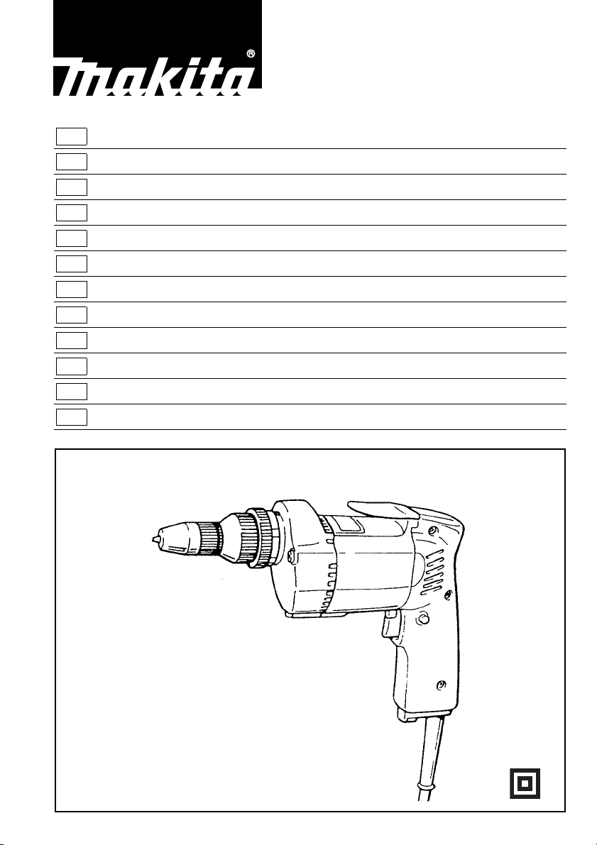
Screwdriver Instruction Manual
F
Visseuse Manuel d’instructions
D
Schrauber Betriebsanleitung
I
Avvitatrice Istruzioni per l’uso
NL
Schroevedraaier Gebruiksaanwijzing
E
Atornillador Manual de instrucciones
P
Aparafusadora Manual de instruções
DK
Skruemaskine Brugsanvisning
S
Skruvdragare Bruksanvisning
N
Skrutrekker Bruksanvisning
SF
Ruuvinväännin Käyttöohje
GR Κατσαβίδι Οδηγίεσ χρήσεωσ
6805BV
12
34
56
78
2

ENGLISH
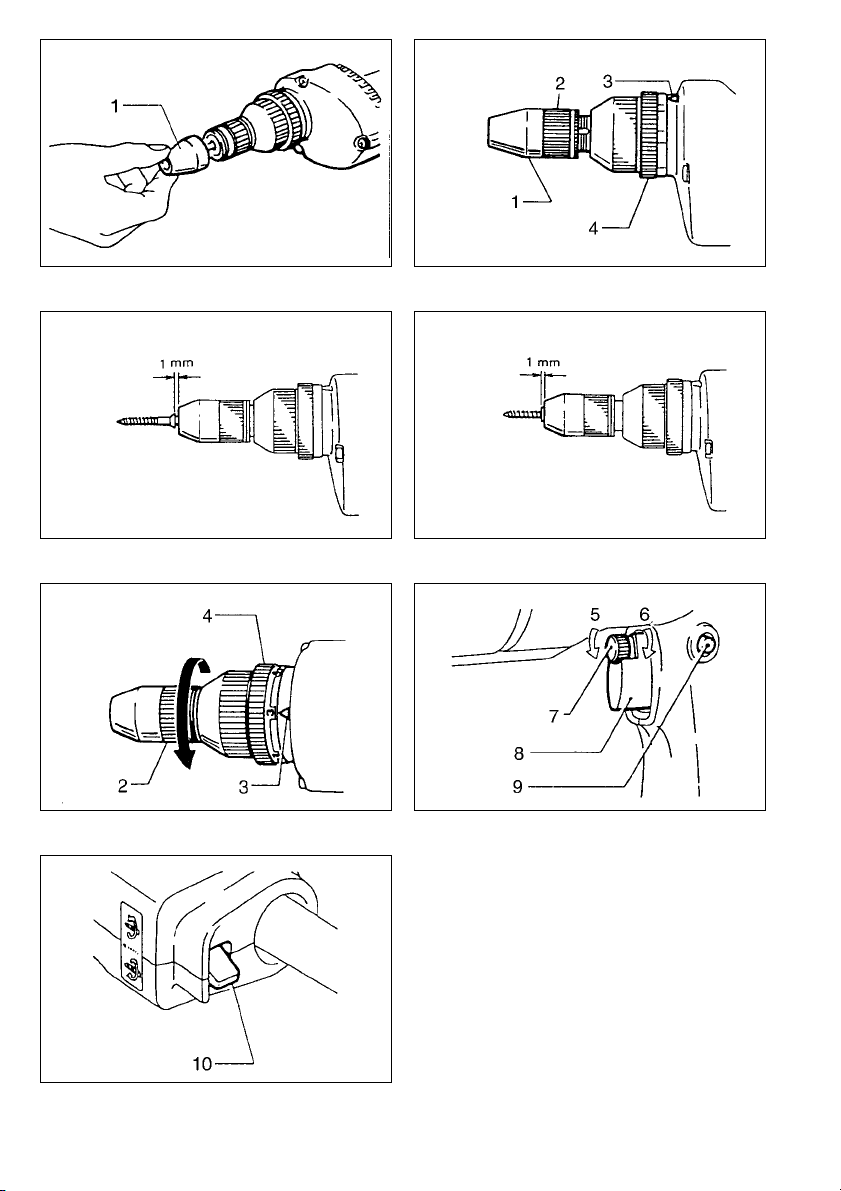
Explanation of general view
1 Front cap
2 Locator
3 Pointer
4 Adjusting ring
5Low
6 High
7 Speed control screw
8 Switch trigger
SPECIFICATIONS
Model 6805BV
Capacities
Self drilling screw .............................. .............6mm
Machine screw ...............................................8 mm
Wood screw ............................................. .. . 6.2 mm
Bit shank size ............................................... 1/4”Hex
No load speed (min
–1
) ................................ 0 – 2,500
Overall length .......................... ......................267mm
Net weight ........................................................1.9kg
• Due to our continuing program of research and
development, the specifications herein are subject
to change without notice.
• Note: Specifications may differ from country to
country.
Power supply
The tool should be connected only to a power supply
of the same voltage as indicated on the nameplate,
and can only be operated on single- phase A C s upply.
They are double-insulated in accordance with European Standard and can, therefore, also be used from
sockets without ea rth wire.
Safety hints
For your own safety, please refer to the enclosed
safety instructions.
SPECIFIC SAFET Y RULES
DO NOT let comfort or familiarity with product
GEB017-1
(gained from repeated use) replace strict
adherence to screwdriver safety rules. If you use
this tool unsafely or incorrectly, you can suffer
serious personal injury.
1. Hold power tools by insulated gripping surfaces
when performing an operation where the cutting
tool may contact hidden wiring or its o wn cord.
Contact with a “live” wire will make exposed metal
parts of the tool “live” and shock the operator.
2. Always be sure you have a firm foot ing. Be s ure
no one is belo w wh en usi ng t he tool i n h igh l o ca tions.
3. Hold the tool firmly.
4. Keep hands away from rotating parts.
5. Do not tou ch the bit or the workpiece imme di-
ately after operatio n; they may be extremely hot
and could burn y o ur skin.
SAVE THESE INSTRUCTIONS.
9 Lock button
10 Reversing switch lever
WARNING:
MISUSE or failure to f ollow the safety rules sta ted
in this instruction manual may cause serious
personal injury.
OPERATING INSTRUCTIONS
Removing or installing th e bit (Fig.1)
Important:
Always be sure that the tool is switched off and
unplugged before removing or installing the bit.
To remove the bit, first pull the front cap off and then
pull the bit firmly. To install the bit, insert it into the
tool as far as it will go and then replace the front cap.
Depth adjustment (Fig.2,3&4)
When you wish to drive self drilling screws, etc.,
adjust the depth as follows. Turn the locator to adjust
the depth.
Initially, adjust the locator to create a distance of
approximately 1mm from the tip of the front cap
(which works in conjunction with the locator) to the
base of the screw head. One full turn of the locator
equals 1mm change in depth. After adjusting the
locator, turn the ad justin g rin g so that the 6" mar k is
aligned with the pointer on the gear housing. Drive a
trial screw into your material or a piece of duplicate
material. If the depth is not suitable for the screw,
continue adjusting until the proper depth setting is
obtained.
Adjusting fastening torque (Fig.5)
When you wish to drive tool screws, wood sc rews,
hex bolts, etc. with the predetermined torque, adjust
the fastening torque as follows. The fastening torque
may be adjusted by turning the adjusting ring. Before
turning the adjusting ring, turn the locator in the
direction of the arrow as far as it will go without forcing. The to rque is incre ased by tur nin g the ad justin g
ring in the direction of the arrow and decreased by
turning it in the opposite direct ion . Align t he n umb er 1
on the adjusting ring with the pointer on the gear
housing. Drive a trial screw into your material or a
piece of duplicate material. If the fastening torque is
not suitable for the screw, continue adjusting until the
proper torque is obtained.
CAUTION:
The adjusting ring should be turned only within the
numbered range. It should not be forced beyond this
range.
3

Switch action (Fig.6)
CAUTION:
Before plugging in the tool, always check to see that
the switch trigger ac tuat es pr operly and ret urns to the
“OFF” position when released.
To start the tool, simply pull the trigger. Tool speed is
increased by increasing pressure on the trigger.
Release the trigger to stop. F or continuous operation,
pull the trigger and then push in the lock button. To
stop the tool from the locked position, pull the trigger
fully, then release it. A speed control screw is provided so that maximum tool speed can be limited
(variable). Tur n the speed control screw clockwise for
higher speed, and counterclockwise for lo wer speed.
NOTE:
Even with the switch on and motor running, the bit
will not rotate until you fit the point of the bit in the
screw head and apply forward pressure to engage
the clutch.
Reversing switch action (Fig.7)
CAUTION:
• Always check the direction of rotation before operation.
• Use the reversing switch only after the tool comes
to a complete stop. Changing the direction of rotation before the tool stops may damage the tool.
This tool has a reversing switch to change the direction of rotation. Move the rev ersing switch lever to the
i position for clockwis e rotation or the j position
for counterclockwise rotation.
Operation
Fit the screw on the point of the bit and place the
point of the screw on the surface of the workpiece to
be fastened. Apply pressure to the tool and star t it.
Withdraw the tool as soon as the clutch cuts in.
CAUTION:
• Use the proper bit f o r t he hea d of the s cre w tha t y ou
wish to use.
• When fitting the screw onto the point of the bit, be
careful not to push in on the screw. If the screw is
pushed in, the clutch will engage and the screw will
rotate suddenly. This could damage a workpiece or
cause an injury.
• Do not continue unnecessary clutching operation.
NOTE:
• Make sure that the driver bit is inserted straight in
the screw head, or the screw and/or bit may be
damaged.
• When driving wood screws, predrill pilot holes to
make driving easier and to prevent splitting of the
workpiece. See the chart.
Nominal diameter of
wood screw (mm)
Recommended size of
pilot hole (mm)
3.1 2.0
3.5 2.2
3.8 2.5
4.5 2.9
4.8 3.1
5.1 3.3
5.5 3.6
5.8 3.8
6.2 4.0
MAINTENANCE
CAUTION:
Always be sure that the tool is switched off and
unplugged before carrying out any work on the tool.
To maintain product safety and reliability, repairs,
maintenance or adjustment should be carried out by
a Makita Authorize d Service Center.
4

FRANÇAIS
1 Positionneur
2 Bague
3 Index
4 Molette de réglage
Descriptif
5 Plus lent
6 Plus rapide
7 Molette du variateur
8 Gâchette
9 Bouton de blocage
10 Inverseur
SPECIFICATIONS
Modèle 6805BV
Capacités
Vis auto-foreuse .............................................6 mm
Vis à tête hexagonale .....................................8 mm
Vis à bois ....................................................6,2 mm
Emmanchement ...................................... 1/4” Hexag.
Vitesse à vide (min
–1
) .................................0 – 2 500
Longueur totale .............................................267 mm
Poids net ..........................................................1,9 kg
• Etant donné l’évolution constante de notre pro-
gramme de recherche et de développement, les
spécifications contenues dans ce manuel sont
sujettes à modification sans préavis.
• Note : Les spécifications peuvent varier suivant les
pays.
Alimentation
L’outil ne devra être raccordé qu’à une alimentation
de la même tension que celle qui figure sur la plaque
signalétique, et il ne pourra fonctionner que sur un
courant secteur monophasé. Réalisé avec une double isolation, il est conforme à la réglementation
européenne et peut de ce fait être alimenté sans
mise à la terre.
Consignes de sécurité
Pour votre propre sécurité, reportez-vous aux consignes de sécurité qui accompagnent l’outil.
PRECAUTIONS SUPPLEMENTAIRES POUR
L’OUTIL
NE vous laissez PAS tromper (au fil d’une
utilisation répétée) par un sentiment d’aisance et
de familiarité avec l’outil, en négligeant le respect
rigoureux des consignes de sécurité qui
accompagnent la visseuse.
1. Saisissez les outils électriques par leurs sur-
faces de poigne isolées lorsque vous effectuez
une opération au cours de laquelle l’outil tranchant peut entrer en contact avec des fils cachés
ou avec son propre cordon d’alimentation.
Le contact avec un fil sous tension mettra les parties
métalliques exposées de l’outil sous tension, causant ainsi un choc électrique chez l’utilisateur.
2. Veillez à toujours avoir un bon équilibre. Vérifiez
qu’il n’y a personne dessous quand vous utilisez
l’outil en hauteur.
3. Tenez l’outil fermement.
4. N’approchez pas les mains des pièces en mou-
vement.
5. Ne touchez ni la vis ni son support immédiatement après un vissage. Ils peuvent être extrêmement chauds et risquer de vous brûler.
CONSERVEZ CES INSTRUCTIONS.
AVERTISSEMENT :
LA MAUVAISE UTILISATION de l’outil ou
l’ignorance des consignes de sécurité du présent
manuel d’instructions peuvent entraîner une
grave blessure.
MODE D’EMPLOI
Pose et dépose du embout (Fig. 1)
Important :
Avant d’installer ou de relirer l’embout, assurez-vous
que le contact est coupé et l’outil débranché.
Pour retirer l’embout, retirez d’abord le positionneur
et tirez ensuite fermement sur l’embout. Pour installer
l’embout, insérez-le dans l’outil aussi loin que possible et replacez le positionneur.
Réglage de profondeur (Fig. 2, 3 et 4)
Quand vous voulez enfoncer des vis auto-foreuse,
etc., réglez la profondeur comme suit.
Faites tourner le positionneur pour ajuster la profondeur.
Ajustez d’abord la bague filetée de façon à laisser
une distance d’environ 1 mm entre l’extrémité du
positionneur et le plat de la tête de vis. Un tour complet du positionneur entraîne une variation de 1 mm
de profondeur. Une fois le positionneur réglé, tournez
la bague de réglage de façon que la marque “6” se
trouve alignée sur l’index du carter. Enfoncez une vis
d’essai dans votre support ou dans un èchantillon
analogue; si la profondeur ne convient pas à la vis,
pour-suivez le réglage jusqu’à ce que la profondeur
correcte soit obtenue.
5

Réglage du couple de serrage (Fig. 5)
Si vous désirez enfoncer des vis à métaux ou à bois,
des boulons six-pans, etc. avec un couple préréglé,
effectuez ce réglage comme suite.
Le couple de serrage peut être ajusté en tournant la
bague de réglage. Avant de la tourner toutefois, faites
tourner le positionneur dans la direction de la flèche
aussi loin qu’il est possible de le faire sans forcer. Le
couple se trouve accru quand vous tournez la bague
dans le sens le la flèche, et diminué quand vous la
tournez dans le sens opposé. Alignez le No 1 de la
bague de réglage sur l’index que porte le carter de
l’outil. Enfoncez une vis d’essai dans votre matériau
ou un matériau équivalent. Si le couple de serrage ne
vous semple pas adéquat, continuez le réglage
jusqu’à ce qu’il se trouve atteint.
ATTENTION :
La bague de réglage ne doit être manoeuvrée que
dans la limite des chiffres et ne doit jamais être
forcée au-delà.
Utilisation de la gâchette (Fig. 6)
ATTENTION :
Avant de brancher l’outil, vérifier toujours que la
gâchette fonctionne correctement et revient sur la
position “OFF” une fois relâchée.
Pour le mettre en route, déprimez simplement la
gâchette. La vitesse augmente avec la pression exercée sur la gachette. Pour l’arrêter, relâchez-la. Pour
une utilisation continue sans la maintenir du doigt
déprimez-la seulement et engagez le bouton de blocage avec le pouce. Pour arrêter l’outil. déprimez
simplement une fois la gâchette et relâchez-la. L’outil
comporte une vis de réglage de la vitesse de sorte
que sa vitesse de rotation peut être modifiée quand
la gâchette est pressée à fond. Le nombre de tours/
minute augmente quand on tourne cette vis vers la
droite et diminue vers la gauche.
NOTE :
L’entrainement de l’embout séffectue par l’intermédiaire d’un embrayage. Une fois le moteur mis en route
appuyez franchement l’embout cóntre la tête de vis
pour obtenir la rotation de l’embout.
Inverseur (Fig. 7)
ATTENTION :
• Vérifiez toujours le sens de rotation avant de commencer visser.
• N’actionnez l’inverseur qu’une fois l’outil complètement arrêté, faute de quoi vous risquez d’endommager définitivement votre outil.
Cet outil est muni d’un inverseur qui permet de
changer le sens de rotation. Mettez-le du côté
pour qu’il tourne vers la droite, et vers j pour qu’il
tourne dans le sens inverse.
i
Fonctionnement
Adaptez la vis à l’extrémité de l’embout et placez la
pointe de la vis sur la surface de la pièce à visser.
Appliquez une pression sur votre outil et faites-le
tourner. Retirez l’outil dès qui il débraye.
ATTENTION :
• Utilisez un embout adapté à la tête de votre vis.
• Quand vous adaptez la vis à l’extrémité de
l’embout, faites attention à ne pas appuyer lsur la
vis. Vous risqueriez d’enclencher l’embrayage et la
vis se mettrait brusquement en rotation, ce qui risquerait d’endommager la pièce à travailler et de
vous blesser.
• Ne faites pas fonctionner l’embrayage plus que
nécessaire.
NOTE :
• Assurez-vous que l’embout se trouve inséré bien
droit dans la tête de vis, faute de quoi vis et embout
risquent de s’endommager.
• Quand vous vissez des vis à bois, le perçage
d’avant-trous rendra votre tâche plus aisée et
empêchera que le matériau ne se fende. Consultez
la partie droite du tableau.
Diamètre nominal
de la vis à bois
(mm)
3,1 2,0
3,5 2,2
3,8 2,5
4,5 2,9
4,8 3,1
5,1 3,3
5,5 3,6
5,8 3,8
6,2 4,0
Diamètre
correspondant de
l’avant-trou (mm)
ENTRETIEN
ATTENTION :
Avant toute intervention, assurez-vous que le contact
est coupé et l’outil débranché.
Pour maintenir la sécurité et la fiabilité du produit, les
réparations, l’entretien ou les réglages doivent être
effectués par le Centre d’Entretien Makita.
6

DEUTSCH
Übersicht
1 Stopper
2 Führungshülse
3 Markierungspfeil
5 Niedriger
6 Höher
7 Drehzahl-Stellrad
4 Einstellring
TECHNISCHE DATEN
Modell 6805BV
Maße
Selbstbohrschrauben......................................6 mm
Maschinenschrauben......................................8 mm
Holzschrauben .............................................6,2 mm
Werkzeugaufnahme..................................... 1/4" HEX
Gesamtlänge (min
–1
)...................................0 – 2 500
Nettogewicht ..................................................... 1,9 kg
>
• Wir behalten uns vor, Änderungen im Zuge der Ent-
wicklung und des technischen Fortschritts ohne
vorherige Ankündigung vorzunehmen.
• Hinweis: Die technischen Daten können von Land
zu Land abweichen.
Netzanschluß
Die Maschine darf nur an die auf dem Typenschild
angegebene Netzspannung angeschlossen werden
und arbeitet nur mit Einphasen-Wechselspannung.
Sie ist entsprechend den Europäischen Richtlinien
doppelt Schutzisoliert und kann daher auch an
Steckdosen ohne Erdanschluß betrieben werden.
Sicherheitshinweise
Lesen und beachten Sie diese Hinweise, bevor Sie
das Gerät benutzen.
ZUSÄTZLICHE
SICHERHEITZSBESTIMMUNGEN
Lassen Sie sich NICHT durch Bequemlichkeit
oder Vertrautheit mit dem Produkt (durch
wiederholten Gebrauch erworben) von der
strikten Einhaltung der SchrauberSicherheitsregeln abhalten.
1. Halten Sie Elektrowerkzeuge nur an den isolier-
ten Griffflächen, wenn Sie Arbeiten ausführen,
bei denen die Gefahr besteht, dass verborgene
Kabel oder das eigene Kabel kontaktiert werden.
Bei Kontakt mit einem stromführenden Kabel werden die freiliegenden Metallteile des Werkzeugs
ebenfalls stromführend, so dass der Benutzer einen
elektrischen Schlag erleiden kann.
2. Sorgen Sie für sicheren Stand und halten Sie
jederzeit Gleichgewicht. Stellen Sie sicher, daß
sich bei Einsatz der Maschine an hochgelegenen
Arbeitsplätzen keine Personen darunter aufhalten.
3. Halten Sie die Maschine sicher fest.
4. Halten Sie die Hände von rotierenden Teilen fern.
8 Elektronikschalter
9 Schalterarretierung
10 Drehrichtungsumschalter
5. Das Einsatzwerkzeug oder das bearbeitete
Werkstück nicht unmittelbar nach Beendigung
der Arbeit berühren. Sie können sehr heiß sein
und Verbrennungen verursachen.
BEWAHREN SIE DIESE HINWEISE
SORGFÄLTIG AUF.
WARNUNG:
MISSBRAUCH oder Missachtung der
Sicherheitsvorschriften in dieser Anleitung
können schwere Verletzungen verursachen.
BEDIENUNGSHINWEISE
Montage bzw. Demontage von
Einsatzwerkzeugen (Abb. 1)
VORSICHT:
Vergewissern Sie sich vor der Montage bzw. Demontage von Einsatzwerkzeugen stets, daß die Maschine
abgeschaltet und der Netzstecker gezogen ist.
Zur Demontage von Einsatzwerkzeugen entfernen
Sie zuerst die Führungshülse und ziehen Sie dann
das Einssatzwerkzeug mit einem kräftigen Ruck heraus. Zur Montage das Einsatzwerkseug so weit wie
möglich in die Maschine einsetzen, anschließend die
Führungshülse wieder aufsetzen.
Tiefenbegrrnzung (Abb. 2, 3 u. 4)
Drehen Sie die Führungshülse zur Tietenbegrenzung
nach rechts oder links. Zur Grundeinstellung sollte
der Schraubendrehereinsatz ca. 1 mm aus der Führungshülse herausragen. Führen Sie eine Probeverschraubung durch. Zur weiteren Einstellung ziehen
Sie die Feststellhülse wieder nach vorn. Dabei
bewirkt eine Umdrehung der Führungshülse eine
Veränderung der Tiefeneinstellung von 1 mm. Die
Drehmomenteinstellung sollte bei dieser Verschraubungsart auf Stufe 6 eingestellt werden.
Einstellung des Drehmoments (Abb. 5)
Zum Verschrauben von Maschinen-, Holz-, Sechskantschrauben u. ä. stellen Sie das gewünschte
Drehmoment wie folgt ein:
Die Führungshülse ohne Kraftaufwand in Pfeilrichtung verstellen. Die Zahl 1 auf dem Einstellring mit
dem Pfeil (Getriebegehäuse) zur Deckung bringen.
Eine Probeverschraubung durchführen. Sollte das
Drehmoment zu gering sein, die Einstellung mit
einem höheren Zahlenwert wiederholen. Den Einstellring nur innerhalb des Zahlenbereichs ohne
Gewaltanwendung verdrehen.
7

VORSICHT:
Der Einstellring sollte nur innerhalb des nummerierten Bereichs gedreht werden. Er sollte nicht über diesen Bereich hinaus gedreht werden.
Schalterfunktion (Abb. 6)
VORSICHT:
Vor dem Anschließen der Maschine an das Stromnetz stets überprüfen, ob der Elektronikschalter ordnungsgemäß funktioniert und beim Loslassen in die
AUS- Stellung zurückkehrt.
Zum Einschalten drücken Sie den Elektronikschalter.
Die Drehzahl erhöht sich durch verstärkte Druckausübung auf den Elektronikschalter. Zum Ausschalten
lassen Sie den Schalter los. Für Dauerbetrieb drükken Sie den Elektronikschalter und gleichzeitig die
Schalterarreiterung. Zum Ausschalten des Dauerbetriebs den Elektronikschalter drücken und wieder loslassen. Die Drehzahl kann über das DrehzahlStellrad bei vollständig gedrücktem Elektronikschalter eingestellt werden. Für höhere Drehzahlen das
Stellrad im Uhrzeigersinn für niedrigere Drehzahlen
gegen den Uhrzeigersinn drehen.
ACHTUNG:
Der Schraubendrehereinsatz dreht sich nur bei
Druckausübung auf die Maschine. Auch bei eingeschalteter Maschine und laufendem Motor kuppelt
die Maschine ohne Druck auf den Schraubendrehereinsatz nicht ein.
Drehrlchtungsumschalter (Abb. 7)
VORSICHT:
• Prüfen Sie stets die Drehrichtung, bevor Sie mit
dem Schraubvorgang beginnen.
• Wechseln Sie niemals die Drehrichtung, bevor der
Motor zum Stillstand gekommen ist. Andernfalls
kann die Maschine beschädigt werden.
Mit dem Drehrichtungsumschalter kann die Drehrichtung verändert werden. Schalten Sie für Rechtslauf
auf die mit
Uhrzeigersinn zu erreichen, für Linkslauf auf die mit
markierte Seite, um eine Rotation entgegen dem
j
Uhrzeigersinn zu erreichen.
markirete Seite, um eine Rotation im
i
Betrieb
Die Schraube in den Schraubendrehereinsatz einsetzen. Mit Druck auf das Gerät die Verschraubung
durchführen. Die Kupplung unterbricht den Schraubvorgang, sobald die eingestelle Einschraubtiefe
erreicht ist.
VORSICHT:
• Verwenden Sie übereinstimmende Größen und
Typen für Schraubendrehereinsätze und Schraubenköpfe
• Die Schraube beim Einsetzen auf den Schraubendrehereinsatz nicht andrücken, da die Gefahr
besteht, daß die Kupplung einrastet und die
Schraube sich dreht. Verletzungen oder Beschädigungen der Werkstückoberfläche könnten verursacht werden.
• Vermeiden Sie unnötiges Ein- und Auskuppeln.
HINWEIS:
• Den Schraubendrehereinsatz senkrecht in den
Schraubenkopf setzen, um eine Beschädigung von
Schraubenkopf und Schraubendrehereinsatz zu
vermeiden.
• In Holz, Holzwerkstoffen und anderen empfindlichen Materialien empfiehlt sich eine Vorbohrung,
um Beschädigungen und Spalten des Materials zu
vermeiden.
Nenndurchmesser der
Holzschraube (mm)
3,1 2,0
3,5 2,2
3,8 2,5
4,5 2,9
4,8 3,1
5,1 3,3
5,5 3,6
5,8 3,8
6,2 4,0
Bohrungsdurch-
messer (mm)
WARTUNG
VORSICHT:
Vor Arbeiten an der Maschine vergewissern Sie sich,
daß sich der Schalter in der "OFF-Position" befindet
und der Netzstecker gezogen ist.
Um die Sicherheit und Zuverlässigkeit dieses Gerätes zu gewährleisten, sollten Reparatur-, Wartungs-,
und Einstellarbeiten nur von durch Makita autorisierten Werkstätter oder Kundendienstzentren unter ausschließlicher Verwendung von MakitaOriginalersatzteilen ausgeführt werden.
8

ITALIANO
1 Copertura frontale
2 Mandrino
3 Freccia
4 Anello di regolazione
Visione generale
5 Basso
6Alto
7 Vite di controllo de velocità
8 Grilletto dell’interruttore
9 Bottone di bloccaggio
10 Operazione inversa
dell’interruttore
DATI TECNICI
Modello 6805BV
Capacità
Vite autoperforante .........................................6 mm
Vite per macchinario ......................................8 mm
Vite in legno ................................................6,2 mm
Attacco della punta .......... ..................1/4” esagonale
Velocità a vuoto (min
–1
) ............. .................0 – 2.500
Lunghezza total e .................................. ... .....267 mm
Peso netto ........................................................1,9 kg
• Per il nostro programma di ricerca e sviluppo con-
tinui, i dati tecnici sono soggetti a modifiche senza
preavviso.
• Nota: I dati tecnici potrebbero differire a seconda
del paese di destinazione de l modello.
Alimentazione
L’utensile deve essere collegato ad una presa di corrente con la stessa tensione indicata sulla targhetta
del nome, e può funzionare soltanto con la corrente
alternata monofase . Es so ha un dopp io isolamen to in
osservanza alle norme europee, per cui può essere
usato con le prese di corrente sprovv iste della messa
a terra.
Consigli per la sicurezza
Per la vostra sicurezza, riferitevi alle accluse istruzioni per la sicurezza.
UL TERIORI REGOL E DI SICUREZZA PER
L’UTENSIL E
NON lasciar e che l a com odità o la f amili arit à con
il prodotto (acquisita con l’uso ripetuto)
sostituisca la stretta osservanza delle norme di
sicurezza per l’avvitatore.
1. Tenere gli utensili elettrici per le superfici di
presa isolate quando si eseguono operazioni
durante le quali l’utensile di taglio potrebbe
venire a co ntatto con fili elet trici n ascosti o co n
il suo stesso cavo di alimentazione.
Il contatto con un filo “sotto t ensione” mette “sotto
tensione” le parti metalliche esposte dell’utensile
causando una scossa all'operatore.
2. Appoggiar e sempre saldamente i piedi a terra.
Accertarsi che non ci sia nessuno sotto quando
si lavora su un posto alto.
3. Tenere saldamente l’uten sile.
4. Tenere le mani lontane dalle parti rotanti.
5. Non toccare la punta o ppure il pezzo sotto lavo-
razione subito dopo la foratura, potrebbero
essere estremamente caldi e causare ustioni alla
pelle.
CONSERVATE QUESTE ISTRUZIONI.
ATTENZIONE:
L’utilizzo SBAGLIATO o la mancata osservanza
delle norme di sicurezza di questo manuale di
istruzioni potrebbero causare serie lesioni
personali.
ISTRUZIONI PER L’USO
Montaggio e smontaggio della punta (Fig. 1)
Importante:
Sempre assicurarsi che l’utensile é staccato dalla
presa di corrente e l’interruttore é staccato prima di
montare oppure smontare la punt a.
Per smontare la punta, per prima cosa tirare via la
copertura frontale e quindi tirare in fuori la punta con
forza. Per montare la punta, inserirla neell’utensile il
più profondamente possibile e quindi rinpiazzare la
copertura frontale.
Regolazione della profondità (Fig. 2, 3 e 4)
Quando volete piazzare una punta a foratura automatica, etc., regolare la profondità nel seguente
modo:
Far girare il mandrino per regolare la profondità.
All’inizio regolare il mandrino per creare una distanza
approssimativa di 1 mm tra l’estremità della copertura frontale (che lavora in tandem con il mandrino) e
la base della testa della vite. Un giro completo del
mandrino é uguale a la 1 mm di avanzamento in profondità. Dopo aver regolato il mandrino, far girare
l’anello di regolazione in modo che il numero 6 v enga
a trovarsi allineato con l’indicatore sul porta mandrino. Fare una prova avvitando una vite su un materiale adatto al caso. Se la profondità non é quella
desiderata, contin ua re la reg olazion e f inchè si ot ti ene
la regolazione adatta alla profondità desiderata.
9

Regolazione della forza di torsione (Fig. 5)
Quando desiderate stringere viti per macchinario, viti
da legname bulloni esagonali, etc. con una forza di
torsione predeterminata regolare la forza di torsione
nel modo seguente:
La forza di torsione può essere regolata facendo
girare l’anello di regolazione. Prima di far girare
l’anello di regolazione, far girare il mandrino nella
direzione della freccia finché si riesce a farla avanzare senza forzature. La forza di torsione aumenta
facendo girare l’anello di regolazione nella direzione
della freccia e diminuisce facendo girare l’anello di
regolazione nella direzione opposta della freccia.
Allineare il numero 1 sull’anello di regolazione con il
segno indicatore sul cor po dell’utensile. Av vitare una
vite prova sul materiale oppure su un pezzo di materiale di ricambio. Se la forza di torsione non è adatta
alla vite, continuare la regolazione finché si ottiene
una forza di torsione adeguata.
PRECAUZIONI:
L’anello di regolazione dovrà essere girato solo
nell’arco compreso tra i numeri non dovrà essere
forzato a uscire da questi limiti.
Operazione dell’interruttore (Fig. 6)
PRECAUZIONI:
Prima di inserire la presa dell’utensile, controllare il
funzionamento dell’interruttore. Schiacciare l’interruttore sul manico per assicurarsi che ritorna alla posizione di fermata dopo essere stato lasciato libero.
Per mettere in moto l’utensile semplicemente schiacciare l’interruttore. La velocità dell’utensile dipende
dalla pressione che si esercita sull’interruttore
dell’utensile. Per fermare l’utensile semplicemente
lasciare andare il dito dall’interruttore. Per ottenere
un moto continuo senza dover tenere schiacciato
l’interruttore basta premere il bottone di bloccaggio.
Per fermare l’utensile dalla posizi on e di bloccaggio in
moto, basta sch iacciare dinuovo l’interruttore e lasciarlo andare. C’è una vite di controllo della velocità
che cambia la velocità (numero di giri) dell’utensile
quando l’interruttore è tenuto completamente schiacciato. Per ottenere una velocità superiore girare la
vite di controllo nel senso dell’orologio, per avere una
velocità inferiore girare la vite di controllo nel senso
contrario.
NOTA:
Anche con il grilletto schiaccitao e il motore in moto,
la punta non comincerà a girare se non è puntata
sulla testa della vite e si applica pressione per mettere in efficienza il locatore.
Operazione inversa dell’interruttore (Fig. 7)
PRECAUZIONI:
• Sempre controllar e la direzion e di rotazione prima
di cominciare la perforazi one.
• Usare l’interruttore di inversione solamente qunado
l’utensile si è fermato completamente.
Questo ut ensile ha un i nterrutto re di reversione che
cambia la direzione di rotazione. Piazzare la levetta
dell’interruttore di riversione nella posizione i per
una rotazione nel senso dell’orologio oppure nella
posizione j per una rotazione nel senso cont rario.
Lavorazione
Piazzare la vite col taglio infilato sulla punta, e piazzare la punta della vite sulla superficie del materiale
che si vuole fissare. Applicare pressione sull’utensile
e metterlo in moto. Ritirare l’utensile appena la frizione entra in fu nzione.
PRECAUZIONI:
• Usare una punta adatta alla mis ura della testa della
vite di cui si desidera far uso.
• Quando si piazza la vite sul taglio della punta, fare
attenzione a non esercitare pressione sulla vite. Se
si esercita pressione sulla vite il mandrino entrerà
in funzione e comincerà a ruotare improvvisamente. Questo può essere la causa di danni sia al
pezzo che di ferite alle persone.
• Non continuare a far girare il mandrino quando non
è necessario.
NOTA:
• Assicurarsi che la punta del trapano é appoggiata
propriamente sulla testa della vite altrimenti o la
vite o la punta ne risulteranno dan neggiate.
• Quando si lavora con viti per il legno fare prima dei
piccoli fori che servano a guidare la vite ed evitare
che si producano crepature sul legno. Vedere la
carta a lato.
Diametro nominale
delle viti da legno
(mm)
3,1 2,0
3,5 2,2
3,8 2,5
4,5 2,9
4,8 3,1
5,1 3,3
5,5 3,6
5,8 3,8
6,2 4,0
Diametro consigli ato
del foro pilota (mm)
MANUTENZIONE
PRECAUZIONI:
Prima di eseguire qualsiasi lavoro sulla macchina,
accertatevi sempre che sia spenta e staccata dalla
presa di corrente.
Per mantenere la sicurezza e l’affidabilità del prodotto, le riparazioni, la manutenzione o le regolazioni
dovrebbero essere eseguite da un centro di assistenza Makita autorizzato.
10
 Loading...