

Page 1
INSTRUCTION MANUAL
MANUEL D'INSTRUCTION
MANUAL DE INSTRUCCIONES
Angle Grinder
Meuleuse d’Angle
Esmeriladora de Disco
9560CV
9561C/9561CV
9563CV
9564C/9564CV
9565CV
004055
DOUBLE INSULATION
DOUBLE ISOLATION
DOBLE AISLAMIENTO
WARNING:
For your personal safety, READ and UNDERSTAND before using.
SAVE THESE INSTRUCTIONS FOR FUTURE REFERENCE.
AVERTISSEMENT:
Pour votre propre sécurité, prière de lire attentivement avant l’utilisation.
GARDER CES INSTRUCTIONS POUR RÉFÉRENCE ULTÉRIEURE.
ADVERTENCIA:
Para su seguridad personal, LEA DETENIDAMENTE este manual antes de usar la herramienta.
GUARDE ESTAS INSTRUCCIONES PARA FUTURA REFERENCIA.
Page 2

ENGLISH
SPECIFICATIONS
Model 9560CV 9561C 9561CV 9563CV 9564C 9564CV 9565CV
Wheel diameter 100 mm (4”) 115 mm (4-1/2”) 115 mm (4-1/2”) 100 mm (4”) 115 mm (4-1/2”) 115 mm (4-1/2”) 125 mm (5”)
Spindle thread M10 x 1.25 5/8” 5/8” M10 x 1.25 5/8” 5/8” 5/8”
No load speed
(RPM)
Overall length 289 mm (11 - 3/8”) 299 mm (11 - 3/4”)
Net weight 1.7 kg (3.7 lbs) 1.8 kg (4.0 lbs)
• Due to our continuing programme of research and development, the specifications herein are subject to change
without notice.
• Note: Specifications may differ from country to country.
2,800 - 10,500 10,500 2,800 - 10,500 2,800 - 10,500 10,500 2,800 - 10,500 2,800 - 10,500
GENERAL SAFETY RULES
USA002-2
(For All Tools)
WARNING:
Read and understand all instructions.
Failure to follow all instructions listed below,
may result in electric shock, fire and/or
serious personal injury.
SAVE THESE INSTRUCTIONS
Work Area
1. Keep your work area clean and well lit. Cluttered
benches and dark areas invite accidents.
2. Do not operate power tools in explosive atmo-
spheres, such as in the presence of flammable
liquids, gases, or dust. Power tools create sparks
which may ignite the dust or fumes.
3. Keep bystanders, children, and visitors away
while operating a power tool. Distractions can
cause you to lose control.
Electrical Safety
4. Double insulated tools are equipped with a
polarized plug (one blade is wider than the
other.) This plug will fit in a polarized outlet only
one way. If the plug does not fit fully in the outlet,
reverse the plug. If it still does not fit, contact a
qualified electrician to install a polarized outlet.
Do not change the plug in any way. Double insula-
tion eliminates the need for the three wire
grounded power cord and grounded power supply
system.
5. Avoid body contact with grounded surfaces
such as pipes, radiators, ranges and refrigera-
tors. There is an increased risk of electric shock if
your body is grounded.
6. Do not expose power tools to rain or wet conditions. Water entering a power tool will increase the
risk of electric shock.
7. Do not abuse the cord. Never use the cord to
carry the tools or pull the plug from an outlet.
Keep cord away from heat, oil, sharp edges or
moving parts. Replace damaged cords immediately. Damaged cords increase the risk of electric
shock.
8. When operating a power tool outside, use an
outdoor extension cord marked “W-A” or “W”.
These cords are rated for outdoor use and reduce
the risk of electric shock.
Personal Safety
9. Stay alert, watch what you are doing and use
common sense when operating a power tool. Do
not use tool while tired or under the influence of
drugs, alcohol, or medication. A moment of inat-
tention while operating power tools may result in
serious personal injury.
10. Dress properly. Do not wear loose clothing or
jewelry. Contain long hair. Keep your hair, clothing, and gloves away from moving parts. Loose
clothes, jewelry, or long hair can be caught in moving parts.
11. Avoid accidental starting. Be sure switch is off
before plugging in. Carrying tools with your finger
on the switch or plugging in tools that have the
switch on invites accidents.
12. Remove adjusting keys or wrenches before turning the tool on. A wrench or a key that is left
attached to a rotating part of the tool may result in
personal injury.
13. Do not overreach. Keep proper footing and balance at all times. Proper footing and balance
enables better control of the tool in unexpected situations.
2
Page 3

14. Use safety equipment. Always wear eye protection. Dust mask, non-skid safety shoes, hard hat, or
hearing protection must be used for appropriate conditions. Ordinary eye or sun glasses are NOT eye
protection.
Tool Use and Care
15. Use clamps or other practical way to secure and
support the workpiece to a stable platform. Hold-
ing the work by hand or against your body is unstable and may lead to loss of control.
16. Do not force tool. Use the correct tool for your
application. The correct tool will do the job better
and safer at the rate for which it is designed.
17. Do not use tool if switch does not turn it on or
off. Any tool that cannot be controlled with the
switch is dangerous and must be repaired.
18. Disconnect the plug from the power source
before making any adjustments, changing
accessories, or storing the tool. Such preventive
safety measures reduce the risk of starting the tool
accidentally.
19. Store idle tools out of reach of children and
other untrained persons. Tools are dangerous in
the hands of untrained users.
20. Maintain tools with care. Keep cutting tools
sharp and clean. Properly maintained tools with
sharp cutting edges are less likely to bind and are
easier to control.
21. Check for misalignment or binding of moving
parts, breakage of parts, and any other condition
that may affect the tools operation. If damaged,
have the tool serviced before using. Many acci-
dents are caused by poorly maintained tools.
22. Use only accessories that are recommended by
the manufacturer for your model. Accessories
that may be suitable for one tool, may become hazardous when used on another tool.
SERVICE
23. Tool service must be performed only by qualified
repair personnel. Service or maintenance per-
formed by unqualified personnel could result in a risk
of injury.
24. When servicing a tool, use only identical
replacement parts. Follow instructions in the
Maintenance section of this manual. Use of unau-
thorized parts or failure to follow Maintenance
instructions may create a risk of electric shock or
injury.
USE PROPER EXTENSION CORD: Make sure your
extension cord is in good condition. When using an
extension cord, be sure to use one heavy enough to
carry the current your product will draw. An undersized
cord will cause a drop in line voltage resulting in loss of
power and overheating. Table 1 shows the correct size to
use depending on cord length and nameplate ampere
rating. If in doubt, use the next heavier gage. The smaller
the gage number, the heavier the cord.
Table 1. Minimum gage for cord
Ampere Rating
Volts Total length of cord in feet
120 V 25 ft. 50 ft. 100 ft. 150 ft.
More Than Not More Than AWG
0 6 18 16 16 14
6 10 18161412
10 12 16 16 14 12
12 16 14 12 Not Recommended
SPECIFIC SAFETY RULES
USB005-4
DO NOT let comfort or familiarity with
product (gained from repeated use)
replace strict adherence to grinder safety
rules. If you use this tool unsafely or
incorrectly, you can suffer serious personal injury.
1. Always use proper guard with grinding wheel. A
guard protects operator from broken wheel fragments.
2. Accessories must be rated for at least the speed
recommended on the tool warning label. Wheels
and other accessories running over rated speed can
fly apart and cause injury.
3. Hold tool by insulated gripping surfaces when
performing an operation where the cutting tool
may contact hidden wiring or its own cord. Con-
tact with a “live” wire will make exposed metal parts
of the tool “live” and shock the operator.
4. When using depressed center grinding wheels,
be sure to use only fiberglass-reinforced wheels.
5. Always use safety glasses or goggles. Ordinary
eye or sun glasses are NOT safety glasses.
6. Check the wheel carefully for cracks or damage
before operation. Replace cracked or damaged
3
Page 4
wheel immediately. Run the tool (with guard) at
no load for about a minute, holding tool away
from others. If wheel is flawed, it will likely separate during this test.
7. Use only flanges specified for this tool.
8. Be careful not to damage the spindle, the flange
(especially the installing surface) or the lock nut.
Damage to these parts could result in wheel
breakage.
9. NEVER use tool with wood cutting blades or
other sawblades. Such blades when used on a
grinder frequently kick and cause loss of control
leading to personal injury.
10. Hold the tool firmly.
11. Keep hands away from rotating parts.
12. Make sure cord is clear of wheel. Do not wrap
cord around your arm or wrist. If control of tool
is lost, cord may become wrapped around you
and cause personal injury.
13. Make sure the wheel is not contacting the workpiece before the switch is turned on.
14. Before using the tool on an actual workpiece, let
it run for a while. Watch for vibration or wobbling
that could indicate poor installation or a poorly
balanced wheel.
15. Use the specified surface of the wheel to perform the grinding.
16. Watch out for flying sparks. Hold the tool so that
sparks fly away from you and other persons or
flammable materials.
17. Do not leave the tool running. Operate the tool
only when hand-held.
18. Do not touch the workpiece immediately after
operation; it may be extremely hot and could
burn your skin.
19. ALWAYS wear proper apparel including long
sleeve shirts, leather gloves and shop aprons to
protect skin from contact with hot grindings.
20. Use of this tool to grind or sand some products,
paints and wood could expose user to dust containing hazardous substances. Use appropriate
respiratory protection.
21. After using the tool, make sure the wheel rotation comes to a complete stop before setting the
tool down. Setting the tool down with the wheel
rotating can cause personal injury.
SAVE THESE INSTRUCTIONS
SYMBOLS
The followings show the symbols used for tool.
V ...........................volts
A...........................amperes
Hz .........................hertz
...................alternating current
.......................no load speed
.......................Class II Construction
.../min
................revolutions or reciprocation per
r/min
minute
USD201-2
FUNCTIONAL DESCRIPTION
CAUTION:
• Always be sure that the tool is switched off and
unplugged before adjusting or checking function on
the tool.
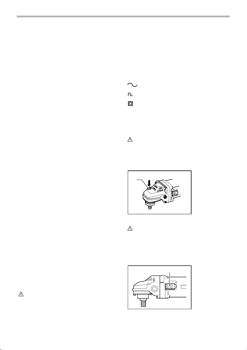
Shaft lock
1
CAUTION:
• Never actuate the shaft lock when the spindle is
moving. The tool may be damaged.
Press the shaft lock to prevent spindle rotation when
installing or removing accessories.
Switch action
002978
1. Shaft lock
001035
1
1. Slide switch
O
WARNING:
MISUSE or failure to follow the safety
rules stated in this instruction manual
may cause serious personal injury.
4
Page 5
CAUTION:
• Before plugging in the tool, always check to see
that the slide switch actuates properly and returns
to the “OFF” position when the rear of the slide
switch is depressed.
• Switch can be locked in “ON” position for ease of
operator comfort during extended use. Apply
caution when locking tool in “ON” position and
maintain firm grasp on tool.
To start the tool, slide the slide switch toward the “I (ON)”
position. For continuous operation, press the front of the
slide switch to lock it.
To stop the tool, press the rear of the slide switch, then
slide it toward the “O (OFF)” position.
Speed adjusting dial
For model 9560CV, 9561CV, 9563CV, 9564CV, 9565CV
only
2
The rotating speed can be changed by turning the speed
adjusting dial to a given number setting from 1 to 5.
Higher speed is obtained when the dial is turned in the
direction of number 5. And lower speed is obtained when
it is turned in the direction of number 1.
Refer to the table below for the relationship between the
number settings on the dial and the approximate rotating
speed.
Number
1
|
2
|
3
|
4
|
5
CAUTION:
• If the tool is operated continuously at low speeds for
a long time, the motor will get overloaded and
heated up.
• The speed adjusting dial can be turned only as far
as 5 and back to 1. Do not force it past 5 or 1, or the
speed adjusting function may no longer work.
The tools equipped with electronic function are easy to
operate because of the following features.
1
RPM (/min)
2,800
|
4,000
|
6,500
|
9,000
|
10,500
001046
1. Speed adjusting dial
001279
Electronic function
Constant speed control
• Possible to get fine finish, because the rotating
speed is kept constant even under the loaded
condition.
• Additionally, when the load on the tool exceeds
admissible levels, power to the motor is reduced to
protect the motor from overheating. When the load
returns to admissible levels, the tool will operate as
normal.
Soft start feature
• Soft start because of suppressed starting shock.
ASSEMBLY
CAUTION:
• Always be sure that the tool is switched off and
unplugged before carrying out any work on the tool.
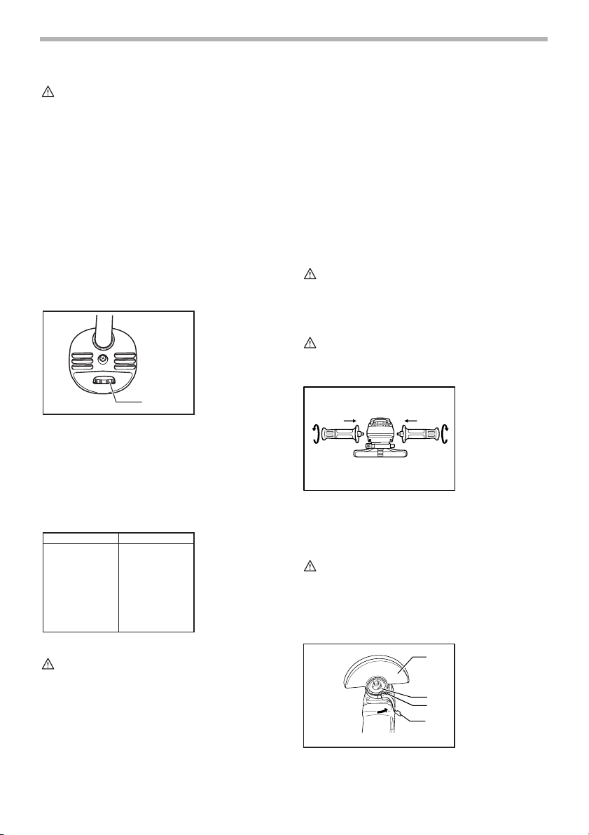
Installing side grip (handle)
CAUTION:
• Always be sure that the side grip is installed
securely before operation.
Screw the side grip securely on the position of the tool as
shown in the figure.
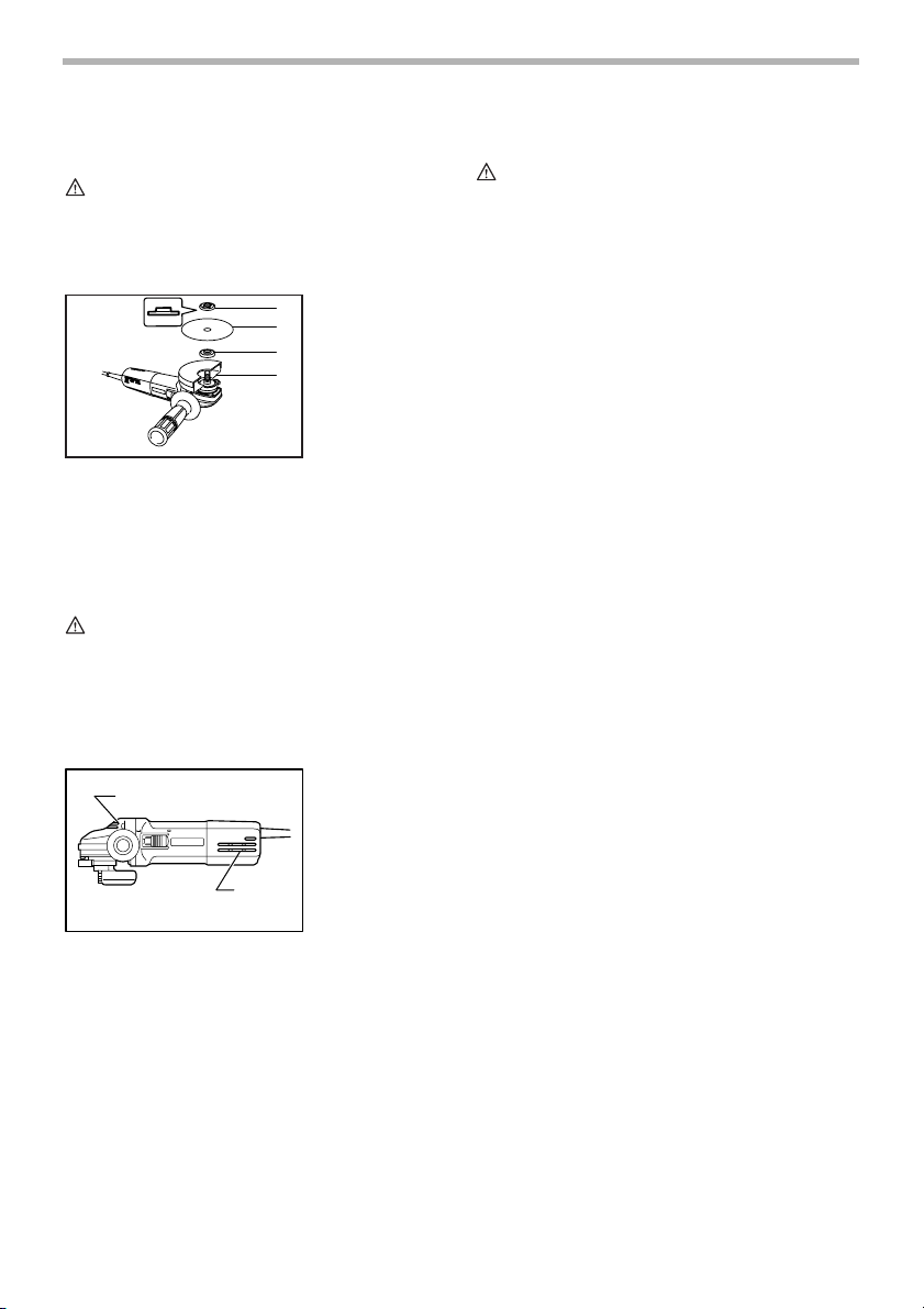
Installing or removing wheel guard
CAUTION:
• When using a depressed center grinding wheel/
Multi-disc, flex wheel, wire wheel brush or cut-off
wheel, the wheel guard must be fitted on the tool so
that the closed side of the guard always points
toward the operator.
002979
002980
1
2
3
4
1. Wheel guard
2. Bearing box
3. Screw
4. Lever
5
Page 6

Loosen the lever on the wheel guard. Mount the wheel
guard with the protrusion on the wheel guard band
aligned with the notch on the bearing box. Then rotate
the wheel guard around 180 degrees. Tighten the lever to
fasten the wheel guard. If the lever is too tight or too
loosen to fasten the wheel guard, loosen or tighten the
screw to adjust the tightening of the wheel guard band.
1
002981
1. Screw
Installing or removing flex wheel
(optional accessory)
WARNIN G:
• Always use supplied guard when flex wheel is on
tool. Wheel can shatter during use and guard helps
to reduce chances of personal injury.
001096
1
2
3
4
1. Lock nut
2. Flex wheel
3. Plastic pad
4. Inner flange
To remove wheel guard, follow the installation procedure
in reverse.
Installing or removing depressed center
grinding wheel/Multi-disc
WARNIN G:
• Always use supplied guard when depressed center
grinding wheel/Multi-disc is on tool. Wheel can
shatter during use and guard helps to reduce
chances of personal injury.
1
Mount the inner flange onto the spindle. Fit the wheel/
disc on the inner flange and screw the lock nut onto the
spindle.
To tighten the lock nut, press the shaft lock firmly so that
the spindle cannot revolve, then use the lock nut wrench
and securely tighten clockwise.
1
2
To remove the wheel, follow the installation procedure in
reverse.
002982
1. Lock nut
2. Depressed cen-
2
3
3. Inner flange
4
4. Spindle
001084
1. Lock nut wrench
2. Shaft lock
ter grinding
wheel/Multi-disc
Follow instructions for depressed center grinding wheel/
Multi-disc but also use plastic pad over wheel. See order
of assembly on accessories page in this manual.
Installing or removing abrasive disc
(optional accessory)
NOTE:
• Use sander accessories specified in this manual.
These must be purchased separately.
Mount the rubber pad onto the spindle. Fit the disc on the
rubber pad and screw the lock nut onto the spindle. To
tighten the lock nut, press the shaft lock firmly so that the
spindle cannot revolve, then use the lock nut wrench and
securely tighten clockwise.
To remove the disc, follow the installation procedure in
reverse.
001107
1
2
3
1. Lock nut
2. Abrasive disc
3. Rubber pad
OPERATION
WARNIN G:
• It should never be necessary to force the tool. The
weight of the tool applies adequate pressure.
Forcing and excessive pressure could cause
dangerous wheel breakage.
• ALWAYS replace wheel if tool is dropped while
grinding.
6
Page 7
• NEVER bang or hit grinding disc or wheel onto
work.
• Avoid bouncing and snagging the wheel, especially
when working corners, sharp edges etc. This can
cause loss of control and kickback.
• NEVER use tool with wood cutting blades and other
sawblades. Such blades when used on a grinder
frequently kick and cause loss of control leading to
personal injury.
CAUTION:
• Never switch on the tool when it is in contact with
the workpiece, it may cause an injury to operator.
• Always wear safety goggles or a face shield during
operation.
• After operation, always switch off the tool and wait
until the wheel has come to a complete stop before
putting the tool down.
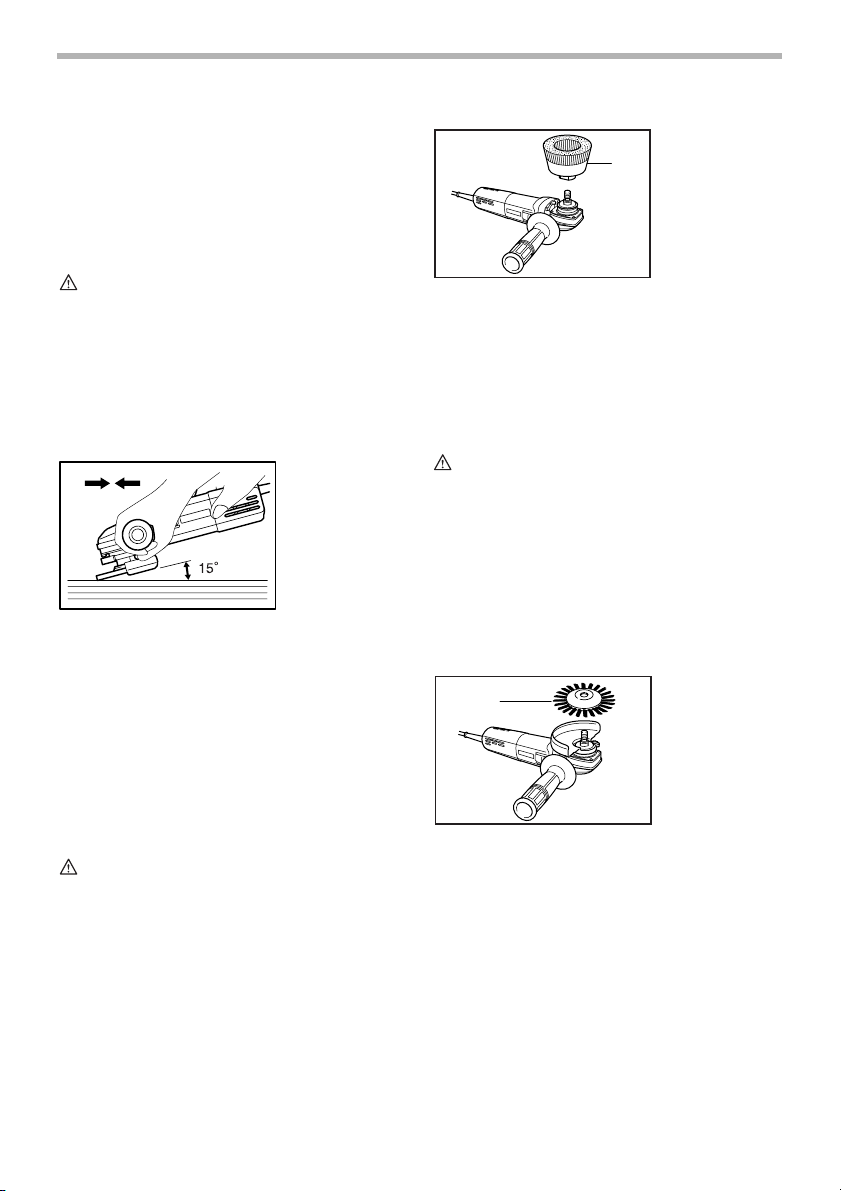
Grinding and sanding operation
AB
ALWAYS hold the tool firmly with one hand on housing
and the other on the side handle. Turn the tool on and
then apply the wheel or disc to the workpiece.
In general, keep the edge of the wheel or disc at an angle
of about 15 degrees to the workpiece surface.
During the break-in period with a new wheel, do not work
the grinder in the B direction or it will cut into the workpiece. Once the edge of the wheel has been rounded off
by use, the wheel may be worked in both A and B direction.
002983
Operation with wire cup brush
(optional accessory)
CAUTION:
• Check operation of brush by running tool with no
load, insuring that no one is in front of or in line with
brush.
• Do not use brush that is damaged, or which is out
of balance. Use of damaged brush could increase
potential for injury from contact with broken brush
wires.
001136
1. Wire cup brush
1
Unplug tool and place it upside down allowing easy
access to spindle. Remove any accessories on spindle.
Thread wire cup brush onto spindle and tighten with supplied wrench. When using brush, avoid applying too
much pressure which causes over bending of wires,
leading to premature breakage.
Operation with wire wheel brush
(optional accessory)
CAUTION:
• Check operation of wire wheel brush by running
tool with no load, insuring that no one is in front of
or in line with the wire wheel brush.
• Do not use wire wheel brush that is damaged, or
which is out of balance. Use of damaged wire
wheel brush could increase potential for injury from
contact with broken wires.
• ALWAYS use guard with wire wheel brushes,
assuring diameter of wheel fits inside guard. Wheel
can shatter during use and guard helps to reduce
chances of personal injury.
1
Unplug tool and place it upside down allowing easy
access to spindle. Remove any accessories on spindle.
Thread wire wheel brush onto spindle and tighten with
the wrenches.
When using wire wheel brush, avoid applying too much
pressure which causes over bending of wires, leading to
premature breakage.
001229
1. Wire wheel
brush
7
Page 8
Operation with abrasive cut-off wheel
(optional accessory)
WARNIN G:
• When using an abrasive cut-off wheel, be sure to
use only the special wheel guard designed for use
with cut-off wheels.
• NEVER use cut-off wheel for side grinding.
During cutting operations, never change the angle of the
wheel. Placing side pressure on the cut-off wheel (as in
grinding) will cause the wheel to crack and break, causing serious personal injury.
001618
1. Lock nut
1
2. Abrasive cut-off
2
3
3. Inner flange
4
4. Wheel guard for
wheel
cut-off wheel
MAINTENANCE
CAUTION:
• Always be sure that the tool is switched off and
unplugged before attempting to perform inspection
or maintenance.
The tool and its air vents have to be kept clean. Regularly
clean the tool’s air vents or whenever the vents start to
become obstructed.
1
002985
1. Exhaust vent
2. Inhalation vent
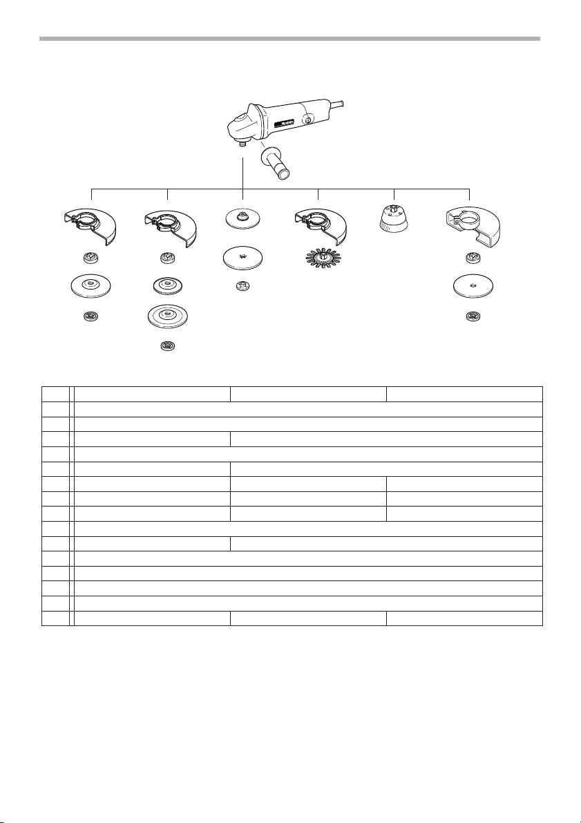
ACCESSORIES
CAUTION:
• These accessories or attachments are
recommended for use with your Makita tool
specified in this manual. The use of any other
accessories or attachments might present a risk of
injury to persons. Only use accessory or
attachment for its stated purpose.
• Your tool is supplied with a guard for use with a
depressed center grinding wheel, multi-disc, flex
wheel and wire wheel brush. A cut-off wheel can
also be used with an optional guard. If you decide
to use your Makita grinder with approved
accessories which you purchase from your Makita
distributor or factory service center, be sure to
obtain and use all necessary fasteners and guards
as recommended in this manual. Your failure to do
so could result in personal injury to you and others.
If you need any assistance for more details regarding
these accessories, ask your local Makita Service Center.
2
To maintain product SAFETY and RELIABILITY, repairs,
carbon brush inspection and replacement, any other
maintenance or adjustment should be performed by Makita Authorized or Factory Service Centers, always using
Makita replacement parts.
8
Page 9
001180
1
2
3
4 14
5
22
6
10
8
9
11
12 13
7
33
5
5
9560CV/9563CV 9561C/9561CV/9564C/9564CV 9565CV
1
2
3 Inner flange 35
4
5 Lock nut 10-35
6 Plastic pad - N/A
7 Flex wheel - N/A
8 Rubber pad 76 Rubber pad 100 Rubber pad 115
9
10 Sanding lock nut 10-30
11
12
13
14
- Lock nut wrench 20 Lock nut wrench 28 Lock nut wrench 28
Depressed center grinding wheel/Multi-disc
Wheel guard (For cut-off wheel)
Grip 36
Wheel guard
Inner flange 45
Lock nut 5/8-45
Abrasive disc
Sanding lock nut 5/8-48
Wire wheel brush
Wire cup brush
Cut-off wheel
006506
9
Page 10

MAKITA LIMITED ONE YEAR WARRANTY
EN0006-1
Warranty Policy
Every Makita tool is thoroughly inspected and tested
before leaving the factory. It is warranted to be free of
defects from workmanship and materials for the period of
ONE YEAR from the date of original purchase. Should
any trouble develop during this one year period, return
the COMPLETE tool, freight prepaid, to one of Makita’s
Factory or Authorized Service Centers. If inspection
shows the trouble is caused by defective workmanship or
material, Makita will repair (or at our option, replace)
without charge.
This Warranty does not apply where:
• repairs have been made or attempted by others:
• repairs are required because of normal wear and
tear:
• the tool has been abused, misused or improperly
maintained:
• alterations have been made to the tool.
IN NO EVENT SHALL MAKITA BE LIABLE FOR ANY
INDIRECT, INCIDENTAL OR CONSEQUENTIAL DAMAGES FROM THE SALE OR USE OF THE PRODUCT.
THIS DISCLAIMER APPLIES BOTH DURING AND
AFTER THE TERM OF THIS WARRANTY.
MAKITA DISCLAIMS LIABILITY FOR ANY IMPLIED
WARRANTIES, INCLUDING IMPLIED WARRANTIES
OF “MERCHANTABILITY” AND “FITNESS FOR A SPECIFIC PURPOSE,” AFTER THE ONE YEAR TERM OF
THIS WARRANTY.
This Warranty gives you specific legal rights, and you
may also have other rights which vary from state to state.
Some states do not allow the exclusion or limitation of
incidental or consequential damages, so the above limitation or exclusion may not apply to you. Some states do
not allow limitation on how long an implied warranty lasts,
so the above limitation may not apply to you.
10
Page 11

FRANÇAIS
SPÉCIFICATIONS
Modèle 9560CV 9561C 9561CV 9563CV 9564C 9564CV 9565CV
Diamètre de la
meule
Filetage de
l’arbre
Vitesse à vide
(T/MIN)
Longueur totale 289 mm (11 - 3/8”) 299 mm (11 - 3/4”)
Poids net 1.7 kg (3.7 lbs) 1.8 kg (4.0 lbs)
• Le fabricant se réserve le droit de modifier sans avertissement les spécifications.
• Note: Les spécifications peuvent varier selon les pays.
100 mm (4”) 115 mm (4-1/2”) 115 mm (4-1/2”) 100 mm (4”) 115 mm (4-1/2”) 115 mm (4-1/2”) 125 mm (5”)
M10 x 1.25 5/8” 5/8” M10 x 1.25 5/8” 5/8” 5/8”
2,800 - 10,500 10,500 2,800 - 10,500 2,800 - 10,500 10,500 2,800 - 10,500 2,800 - 10,500
RÈGLES DE SÉCURITÉ
GÉNÉRALES
USA002-2
(Pour tous les outils)
AVERTISSEMENT:
Vous devez lire et comprendre toutes les
instructions. Le non-respect, même partiel,
des instructions ci-après entraîne un risque
de choc électrique, d’incendie et/ou de
blessures graves.
CONSERVEZ CES
INSTRUCTIONS
Aire de travail
1. Veillez à ce que l’aire de travail soit propre et
bien éclairée. Le désordre et le manque de lumière
favorisent les accidents.
2. N’utilisez pas d’outils électriques dans une
atmosphère explosive, par exemple en présence
de liquides, de gaz ou de poussières
inflammables. Les outils électriques créent des
étincelles qui pourraient enflammer les poussières
ou les vapeurs.
3. Tenez à distance les curieux, les enfants et les
visiteurs pendant que vous travaillez avec un
outil électrique. lls pourraient vous distraire et vous
faire une fausse manoeuvre.
Sécurité électrique
4. Les outils à double isolation sont équipés d’une
fiche polarisée (une des lames est plus large que
l’autre), qui ne peut se brancher que d'une seule
façon dans une prise polarisée. Si la fiche
n’entre pas parfaitement dans la prise, inversez
sa position ; si elle n’entre toujours pas bien,
demandez à un électricien qualifié d’installer une
prise de courant polarisée. Ne modifiez pas la
fiche de l’outil. La double isolation élimine le
besoin d’un cordon d’alimentation à trois fils avec
mise à la terre ainsi que d’une prise de courant mise
à la terre.
5. Évitez tout contact corporel avec des surfaces
mises à la terre (tuyauterie, radiateurs,
cuisinières, réfrigérateurs, etc.). Le risque de
choc électrique est plus grand si votre corps est en
contact avec la terre.
6. N’exposez pas les outils électriques à la pluie ou
à l’eau. La présence d’eau dans un outil électrique
augmente le risque de choc électrique.
7. Ne maltraitez pas le cordon. Ne transportez pas
l’outil par son cordon et ne débranchez pas la
fiche en tirant sur le cordon. N’exposez pas le
cordon à la chaleur, à des huiles, à des arêtes
vives ou à des pièces en mouvement.
Remplacez immédiatement un cordon
endommagé. Un cordon endommagé augmente le
risque de choc électrique.
8. Lorsque vous utilisez un outil électrique à
l’extérieur, employez un prolongateur pour
l’extérieur marqué “W-A” ou “W”. Ces cordons
sont faits pour être utilisés à l’extérieur et réduisent
le risque de choc électrique.
Sécurité des personnes
9. Restez alerte, concentrez-vous sur votre travail
et faites preuve de jugement. N’utilisez pas un
outil électrique si vous êtes fatigué ou sous
l'influence de drogues, d’alcool ou de
médicaments. Un instant d’inattention suffit pour
entraîner des blessures graves.
10. Habillez-vous convenablement. Ne portez ni
vêtements flottants ni bijoux. Confinez les
11
Page 12

cheveux longs. N’approchez jamais les
cheveux, les vêtements ou les gants des pièces
en mouvement. Des vêtements flottants, des bijoux
ou des cheveux longs risquent d’être happés par
des pièces en mouvement.
11. Méfiez-vous d’un démarrage accidentel. Avant
de brancher l’outil, assurez-vous que son
interrupteur est sur ARRÊT. Le fait de transporter
un outil avec le doigt sur la détente ou de brancher
un outil dont l’interrupteur est en position MARCHE
peut mener tout droit à un accident.
12. Enlevez les clés de réglage ou de serrage avant
de démarrer l’outil. Une clé laissée dans une pièce
tournante de l’outil peut provoquer des blessures.
13. Ne vous penchez pas trop en avant. Maintenez
un bon appui et restez en équilibre en tout
temps. Un bonne stabilité vous permet de mieux
réagir à une situation inattendue.
14. Utilisez des accessoires de sécurité. Portez
toujours des lunettes ou une visière. Selon les
conditions, portez aussi un masque antipoussière,
des bottes de sécurité antidérapantes, un casque
protecteur et/ou un appareil antibruit. Les lunettes
ordinaires et les lunettes de soleil NE constituent
PAS des lunettes de protection.
Utilisation et entretien des outils
15. Immobilisez le matériau sur une surface stable
au moyen de brides ou de toute autre façon
adéquate. Le fait de tenir la pièce avec la main ou
contre votre corps offre une stabilité insuffisante et
peut amener un dérapage de l’outil.
16. Ne forcez pas l’outil. Utilisez l’outil approprié à
la tâche. L’outil correct fonctionne mieux et de façon
plus sécuritaire. Respectez aussi la vitesse de
travail qui lui est propre.
17. N’utilisez pas un outil si son interrupteur est
bloqué. Un outil que vous ne pouvez pas
commander par son interrupteur est dangereux et
doit être réparé.
18. Débranchez la fiche de l’outil avant d’effectuer
un réglage, de changer d’accessoire ou de
ranger l’outil. De telles mesures préventives de
sécurité réduisent le risque de démarrage accidentel
de l’outil.
19. Rangez les outils hors de la portée des enfants
et d’autres personnes inexpérimentées. Les
outils sont dangereux dans les mains d’utilisateurs
novices.
20. Prenez soin de bien entretenir les outils. Les
outils de coupe doivent être toujours bien
affûtés et propres. Des outils bien entretenus, dont
les arêtes sont bien tranchantes, sont moins
susceptibles de coincer et plus faciles à diriger.
21. Soyez attentif à tout désalignement ou
coincement des pièces en mouvement, à tout
bris ou à toute autre condition préjudiciable au
bon fonctionnement de l’outil. Si vous constatez
qu’un outil est endommagé, faites-le réparer
avant de vous en servir. De nombreux accidents
sont causés par des outils en mauvais état.
22. N’utilisez que des accessoires que le fabricant
recommande pour votre modèle d’outil. Certains
accessoires peuvent convenir à un outil, mais être
dangereux avec un autre.
RÉPARATION
23. La réparation des outils électriques doit être
confiée à un réparateur qualifié. L’entretien ou la
réparation d’un outil électrique par un amateur peut
avoir des conséquences graves.
24. Pour la réparation d’un outil, n’employez que
des pièces de rechange d’origine. Suivez les
directives données à la section «ENTRETIEN» de
ce manuel. L’emploi de pièces non autorisées ou le
non-respect des instructions d’entretien peut créer
un risque de choc électrique ou de blessures.
UTLISEZ UN CORDON PROLONGATEUR ADÉQUAT:
Assurez-vous que le cordon prolongateur est en bon
état. Lors de l’utilisation d’un cordon prolongateur,
utilisez sans faute un cordon assez gros pour conduire le
courant que le produit nécessite. Un cordon trop petit
provoquera une baisse de tension de secteur, résultant
en une perte de puissance et une surchauffe. Le Tableau
1 indique la dimension appropriée de cordon selon sa
longueur et selon l’intensité nominale indiquée sur la
plaque signalétique. En cas de doute sur un cordon
donné, utilisez le cordon suivant (plus gros). Plus le
numéro de gabarit indiqué est petit, plus le cordon est
gros.
Tableau 1. Gabarit minimum du cordon
Intensité nominale
Volts Longueur totale du cordon en pieds
120 V 25 pi 50 pi 100 pi 150 pi
Plus de Pas plus de Calibre américain des fils
0 6 18 16 16 14
6 10 18161412
10 12 16 16 14 12
12 16 14 12 Non recommandé
12
Page 13

RÈGLES DE SÉCURITÉ
PARTICULIÈRES
USB005-4
NE PAS se laisser détromper par un
excès de confiance consécutif à un
usage fréquent de la meule et se
substituant à l'observation scrupuleuse
des règles de sécurité prescrites.
L'emploi de cet outil de façon incorrecte
ou dangereuse risque d'entraîner des
blessures sérieuses.
1. Utilisez toujours un protecteur de meule
approprié. Le protecteur arrête les éclats en cas de
bris de la meule.
2. Les accessoires doivent être prévus pour au
moins la vitesse recommandée sur l’étiquette de
mise en garde de l’outil. Les meules et autres
accessoires, s’ils tournent au-delà de la vitesse
nominale, risquent d’éclater et de provoquer des
blessures.
3. Tenez l’outil par ses surfaces de prise isolées
pendant toute opération où l’outil de coupe
pourrait venir en contact avec un câblage
dissimulé ou avec son propre cordon. En cas de
contact avec un conducteur sous tension, les pièces
métalliques à découvert de l’outil transmettraient un
choc électrique à l’utilisateur.
4. En utilisant des meules à moyeu déporté, se
servir uniquement de disques renforcés à fibre
de verre.
5. Utiliser sans faute des lunettes de sécurité. Des
lunettes ordinaires ou de soleil ne conviennent
PAS à cet usage.
6. Avant utilisation, vérifiez avec soin l’état de la
meule (fentes ou dégâts). Changez
immédiatement toute meule endommagée. Faire
tourner l’outil (muni du carter correspondant) à
vide pendant environ une minute, en l’écartant
des autres. Si le disque est défectueux, il se
trouvera probablement désemparé durant cet
essai.
7. N’utilisez que des flasques spécifiées pour cet
outil.
8. Veillez à ne pas endommager l’axe, la flasque
(notamment la face de pose) ou l’écrou de
blocage. Vous risqueriez de briser votre meule.
9. NE JAMAIS utiliser l’outil avec des lames
coupantes à bois ou autres lames. De telles
lames employées sur une meule chassent
fréquemment en causant une perte de contrôle
qui risque d’entraîner des blessures.
10. Tenez votre outil fermement.
11. Gardez les mains éloignées des pièces en
mouvement.
12. Ecarter à tout prix le cordon du disque. Ne pas
enrouler le cordon autour du bras ou du poignet.
Si l’on perd le contrôle de l’outil, le cordon
risque de s’enchevêtrer autour de soi et causer
des blessures.
13. Assurez-vous que la meule n’est pas au contact
de la pièce à meuler avant de mettre le contact.
14. Avant de meuler une pièce, laissez tourner votre
outil un moment à vide. Attention aux
mouvements latéraux ou aux vibrations
entraînés par une pose défectueuse de la meule
ou une meule mal équilibrée.
15. Ne meulez qu’avec la partie de la meule
spécifiée pour cela.
16. Attention aux étincelles. Gardez à distance toute
personne, tout matériau inflammable qu’elles
pourraient atteindre.
17. Ne laissez pas une meuleuse en train de tourner.
Nefaites fonctionner l’outil qu’une fois bien en
mains.
18. Ne touchez pas la pièce meulée juste après le
meulage; elle risque d’être très chaude et
pourrait vous brûler.
19. Porter TOUJOURS des vêtements appropriés,
sans oublier une veste à manches longues, des
gants en cuir ainsi qu’un tablier d’atelier pour
éviter le contact de la peau avec les copeaux
brûlants.
20. L’emploi de cet outil pour meuler ou abraser
certaines matières, des parties peintes ou en
bois risque d’exposer l’opérateur aux
poussières contenant des substances nocives.
A cet occasion, il convient alors de se munir
d’une protection respiratoire adéquate.
21. Une fois l’utilisation terminée, assurez-vous que
la meule ne tourne plus avant de déposer l’outil.
Il y a risque de blessure si vous déposez l’outil
alors que la meule tourne encore.
SUIVEZ STRICTEMENT CES
INSTRUCTIONS
AVERTISSEMENT:
UNE UTILISATION ERRONEE ou
l’inobservation des règles de sécurité
préconisées dans ce manuel
d’instructions risque d’entraîner des
blessures sérieuses.
13
Page 14

SYMBOLES
Les symboles utilisés pour l’outil sont présentés cidessous.
V............................volts
A ...........................ampères
Hz..........................hertz
....................courant alternatif
.......................vitesse à vide
.......................construction, catégorie II
.../min
................tours ou alternances par minute
r/min
USD201-2
DESCRIPTION DU
FONCTIONNEMENT
ATTENTION:
• Assurez-vous toujours que l’outil est hors tension et
débranché avant de l’ajuster ou de vérifier son
fonctionnement.
Blocage de l’arbre
1
002978
1. Verrouillage de
l’axe
Interrupteur
ATTENTION:
• Avant de brancher l’outil, assurez-vous toujours
que la gâchette fonctionne correctement et revient
en position d’“OFF” lorsque la partie arrière de
l’interrupteur à glissière est enfoncée.
• Pour rendre le travail de l’utilisateur plus confortable
lors d’une utilisation prolongée, l’interrupteur peut
être verrouillé en position de marche. Soyez
prudent lorsque vous verrouillez l’outil en position
de marche, et maintenez une poigne solide sur
l’outil.
Pour mettre l’outil en marche, faites glisser l’interrupteur
à glissière vers la positon d’“I (ON)". Pour une utilisation
continue, appuyez sur la partie avant de l’interrupteur à
glissière pour le verrouiller.
Pour arrêter l’outil, appuyez sur la partie arrière de
l’interrupteur à glissière, puis faites-le glisser vers la
position d’“O (OFF)".
001035
1
1. Commutateur à
curseur
O
Cadran de rélage de vitesse
Pour les modèles 9560CV, 9561CV, 9563CV, 9564CV
et 9565CV uniquement
001046
1. Cadran de
réglage de la
vitesse
ATTENTION:
• N’activez jamais le blocage de l’arbre alors que
l’arbre bouge. Vous pourriez endommager l’outil.
Appuyez sur le blocage de l’arbre pour empêcher l’arbre
de tourner lors de l’installation ou du retrait des
accessoires.
2
1
On peut changer la vitesse de rotation en tournant le
cadran de réglage de vitesse sur un numéro donné
compris entre 1 et 5.
La vitesse s’accroît à mesure qu’on tourne le cadran vers
le numéro 5, et la vitesse décroît à mesure qu’on tourne
le cadran vers le numéro 1.
Se référer au tableau ci-dessous pour la comparaison
14
Page 15

entre les numéros de réglage du cadran et la vitesse de
rotation approximative.
Numéro
• Si l’outil est utilisé de manière continue à vitesse
• Le cadran de réglage de la vitesse ne peut pas
Les caractéristiques qui suivent facilitent l’utilisation des
outils munis de fonctions électroniques.
Tours par minute (/min)
1
|
2
|
3
|
4
|
5
ATTENTION:
réduite sur une période prolongée, le moteur sera
surchargé et chauffera.
dépasser le 5 et le 1. Ne le forcez pas à dépasser le
5 ou le 1, sinon la fonction de réglage de la vitesse
risque de ne plus fonctionner.
2,800
4,000
6,500
9,000
10,500
001279
|
|
|
|
Fonction électronique
Commande de vitesse constante
• La vitesse de rotation étant maintenue constante
même lorsque l’outil est soumis à une charge de
travail, il est possible d’atteindre une grande finesse
de finition.
• De plus, lorsque la charge imposée à l’outil
dépasse le niveau permis, l’alimentation du moteur
est réduite pour le protéger contre la surchauffe. Le
fonctionnement normal de l’outil est rétabli lorsque
la charge imposée revient à un niveau permis.
Fonction de démarrage en douceur
• La suppression du choc de démarrage permet un
démarrage en douceur.
ASSEMBLAGE
ATTENTION:
• Avant d’effectuer toute intervention sur l’outil,
assurez-vous toujours qu’il est hors tension et
débranché.
Installation de la poignée latérale (poignée)
ATTENTION:
• Avant d’utiliser l’outil, assurez-vous toujours que la
poignée latérale est installée de façon sûre.
Vissez la poignée latérale à fond sur la position de l’outil
comme illustré sur la figure.
002979
Installation ou retrait du carter de meule
ATTENTION:
• En utilisant un disque multiple/roue de meulage à
centre concave, roue de meulage flexible, roue à
brosse métallique ou roue de tronçonnage, le
protecteur de roue de meulage doit être monté sur
l’outil de façon que le côté fermé du protecteur soit
toujours dirigé vers l’opérateur.
Desserrer le levier du protecteur de roue de meulage.
Monter le protecteur de roue de meulage avec la partie
saillante du collier protecteur de roue de meulage
coïncidant avec l’encoche de la cage de roulement.
Ensuite, tourner le protecteur de roue de meulage
d’environ 180°. Serrer le levier pour immobiliser le
protecteur de roue de meulage. Si le levier est trop
bloqué ou trop lâche pour serrer le protecteur de roue de
meulage, desserrer ou resserrer la vis pour ajuster le
degré de serrage du collier protecteur de roue de
meulage.
1
002980
1
2
3
4
002981
1. Carter de meule
2. Boîtier
d’engrenage
3. Vis
4. Levier
1. Vis
15
Page 16

Pour retirer le carter de meule, suivez la procédure de
l’installation de l’autre côté.
Installation ou démontage du disque multiple/
roue de meulage à centre concave.
AVERTISSEMENT:
• Utiliser toujours le protecteur fourni lorsque le
disque multiple/roue de meulage à centre concave
est monté sur l’outil. La roue de meulage peut se
briser durant l’utilisation et le protecteur sert à
réduire les risques de blessures.
1
Monter la bague interne sur la broche. Disposer le
disque/roue de meulage sur la bague interne et visser
l’écrou de verrouillage sur la broche.
Pour serrer le contre-écrou, appuyez fermement sur le
blocage de l’arbre pour empêcher l’arbre de tourner, puis
utilisez la clé à contre-écrou en serrant fermement dans
le sens des aiguilles d’une montre.
1
002982
1. Ecrou de
2
2. Meule à moyeu
3
4
3. Bague interne
4. Arbre
001084
1. Clé d’écrou de
2. Verrouillage de
verrouillage
déporté/Multidisque
verrouillage
l’axe
de meulage peut se briser durant l’utilisation et le
protecteur aide à réduire les risques de blessures.
Suivez les instructions données pour la meule ou le
multidisque à moyeu déporté, mais en plaçant également
un plateau en plastique sur la meule. Pour l’ordre
d’assemblage, référez-vous à la page des accessoires
du présent manuel.
001096
1
2
3
4
1. Ecrou de
verrouillage
2. Disque de
finition en fibre
3. Plastique
caoutchouc
4. Bague interne
Installation ou retrait du disque abrasif
(accessoire en option)
NOTE:
• Utilisez les accessoires de ponçage recommandés
dans le présent manuel d’instructions. Ces derniers
doivent être achetés séparément.
001107
1
2
3
1. Ecrou de
verrouillage
2. Disque abrasif
3. Patin en
caoutchouc
2
Pour retirer la meule, suivez la procédure de l’installation
de l’autre côté.
Installation ou retrait de la meule flexible
(accessoire en option)
AVERTISSEMENT:
• Utiliser toujours le protecteur fourni quand la roue
de meulage flexible est montée sur l’outil. La roue
Montez le plateau de caoutchouc sur l’arbre. Ajustez le
disque sur le plateau de caoutchouc et vissez le contreécrou sur l’arbre. Pour serrer le contre-écrou, appuyez
fermement sur le blocage de l’arbre pour empêcher
l’arbre de tourner, puis utilisez la clé à contre-écrou en
serrant fermement dans le sens des aiguilles d’une
montre.
Pour retirer le disque, suivez la procédure d’installation
de l’autre côté.
UTILISATION
AVERTISSEMENT:
• l n’est jamais nécessaire de forcer l’outil. Le poids
de l’outil lui-même suffit à assurer une pression
adéquate. Le fait de forcer l’outil ou d’appliquer une
pression excessive comporte un risque dangereux
de casser la meule.
• Remplacez TOUJOURS la meule lorsque vous
échappez l’outil pendant le meulage.
• Ne frappez JAMAIS le disque de meulage ou la
meule contre la pièce à travailler.
16
Page 17

• Évitez de laisser la meule sautiller ou accrocher,
tout spécialement lorsque vous travaillez dans les
coins, sur les bords tranchants, etc. Cela peut
causer une perte de contrôle et un choc en retour.
• N’utilisez JAMAIS cet outil avec des lames à bois et
autres lames de scie. Les lames de ce type sautent
fréquemment lorsqu’elles sont utilisées sur une
meuleuse et risquent d’entraîner une perte de
contrôle pouvant causer des blessures.
ATTENTION:
• Ne mettez jamais l’outil en marche alors qu’il se
trouve en contact avec la pièce à travailler, pour
éviter de vous blesser.
• Portez toujours des lunettes à coques de sécurité
ou un écran facial pendant l’opération.
• Après l’utilisation, mettez toujours l’outil hors
tension et attendez l’arrêt complet de la meule
avant de déposer l’outil.
Opérations de meulage et de ponçage
AB
TOUJOURS tenir l’outil fermement avec une main posée
sur le blindage et l’autre retenant le manche latéral.
Mettre l’outil en marche et appliquer la roue de meulage
ou le disque sur la pièce d’usinage.
En général, maintenir le bord de la roue de meulage ou
du disque à un angle d’environ 15 degrés sur la surface
de la pièce d’usinage.
Durant la période de rodage d’une nouvelle roue de
meulage, ne pas utiliser la meule dans le sens B, sinon
elle plongerait dans la pièce d’usinage. Une fois que le
bord de la roue de meulage ait été arrondi à l’usage, la
roue de meulage peut servir dans les deux sens A et B.
002983
Utilisation avec une brosse coupe métallique
(accessoire en option)
endommagée augmente les risques de blessure au
contact des fils cassés.
Débrancher l’outil et le disposer tête en bas pour
permettre d’accéder facilement à la broche. Démonter
tout accessoire se trouvant sur la broche. Enfoncer la
brosse métallique à coupelle sur la broche et la serrer
avec la clé fournie. En utilisant la brosse, éviter de
presser de trop pour éviter de courber excessivement les
fils métalliques, ce qui pourrait conduire à une mise hors
d’usage prématurée.
001136
1
1. Brosse
métallique à
coupelle
Utilisation avec une brosse métallique
circulaire (accessoire en option)
ATTENTION:
• Vérifiez le fonctionnement de la brosse métallique
circulaire en faisant fonctionner l’outil sans charge,
en vous assurant que personne ne se trouve
devant la brosse métallique circulaire ou sur sa
trajectoire.
• N’utilisez pas la brosse métallique circulaire si elle
est endommagée ou déséquilibrée. L’utilisation
d’une brosse métallique circulaire endommagée
augmente les risques de blessure au contact des
fils cassés.
• Avec les brosses métalliques circulaires, utilisez
TOUJOURS le carter, en vous assurant que le
diamètre de la brosse n’est pas trop grand pour le
carter. La brosse peut se casser en cours
d’utilisation et le carter réduit alors les risques de
blessure.
1
001229
1. Brosse
métallique à
roue
ATTENTION:
• Vérifiez le fonctionnement de la brosse en faisant
fonctionner l’outil sans charge, en vous assurant
que personne ne se trouve devant la brosse ou sur
sa trajectoire.
• N’utilisez pas la brosse si elle est endommagée ou
déséquilibrée. L’utilisation d’une brosse
Débranchez l’outil et placez-le la tête en bas pour
permettre un accès facile à l’arbre. Retirez tous les
accessoires de l’arbre. Enfilez la brosse métallique
circulaire sur l’arbre et serrez avec les clés.
Lorsque vous utilisez la brosse métallique circulaire,
évitez d’appliquer une pression telle que les fils seront
17
Page 18

trop pliés et se casseront plus rapidement que lors d’une
utilisation normale.
Fonctionnement avec une meule abrasive à
tronçonner (accessoire en option)
AVERTISSEMENT:
• En utilisant une meule abrasive à tronçonner,
utiliser sans faute le protecteur de roue spécial
conçu essentiellement à cette intention.
• NE JAMAIS utiliser de meule à tronçonner pour le
meulage latéral.
Ne modifiez jamais l’angle de la meule pendant la coupe.
La meule à tronçonner se fissurera ou se cassera si vous
lui appliquez une pression latérale (comme pour le
meulage), entraînant un risque de blessure grave.
001618
1. Ecrou de
1
2
2. Roue abrasive
3
4
3. Bague interne
4. Protecteur pour
verrouillage
de tronçonnage
roue de
tronçonnage
ENTRETIEN
ATTENTION:
• Assurez-vous toujours que l’outil est hors tension et
débranché avant d’y effectuer tout travail
d’inspection ou d’entretien.
L’outil et ses orifices d’aération doivent être maintenus
propres. Nettoyez régulièrement les orifices d’aération de
l’outil, ou chaque fois qu’ils commencent à se boucher.
1
002985
1. Orifice de sortir
2. Orifice d’entrée
d’air
d’air
ACCESSOIRES
ATTENTION:
• Ces accessoires ou pièces complémentaires sont
recommandés pour l’utilisation avec l’outil Makita
spécifié dans ce mode d’emploi. L’utilisation de tout
autre accessoire ou pièce complémentaire peut
comporter un risque de blessure. N’utilisez les
accessoires ou pièces qu’aux fins auxquelles ils ont
été conçus.
• Cet outil est doté d’un protecteur servant
conjointement avec une roue de meulage, disque
multiple, roue de meulage flexible et roue à brosse
métallique à centre concave. Une roue de
tronçonnage peut également être utilisée
conjointement avec un protecteur en option. Si l’on
envisage d’utiliser la meule avec des accessoires
approuvés Makita obtenus au centre d’entretien ou
chez le distributeur Makita, ne pas manquer de se
procurer et d’utiliser également toutes les pièces de
serrage et protecteurs recommandés dans ce
manuel. L’inobservation de ce conseil risquerait
d’entraîner des blessures à soi-même ou à d’autres
personnes se trouvant à proximité.
Si vous désirez obtenir plus de détails concernant ces
accessoires, veuillez contacter le centre de service
après-vente Makita le plus près.
2
Pour maintenir la SÉCURITÉ et la FIABILITÉ du produit,
les réparations, l’inspection et le remplacement des
charbons, et tout autre travail d’entretien ou de réglage
doivent être effectués dans une usine ou un centre de
service après-vente Makita agréé, exclusivement avec
des pièces de rechange Makita.
18
Page 19

001180
1
2
3
4 14
5
22
6
10
8
9
11
12 13
7
33
5
5
9560CV/9563CV 9561C/9561CV/9564C/9564CV 9565CV
1
2
3 Flasque intérieur 35
4
5 Contre-écrou 10-35
6 Plateau en plastique - N/D
7 Meule flexible - N/D
8 Coussinet de caoutchouc 76 Coussinet de caoutchouc 100 Coussinet de caoutchouc 115
9
10 Contre-écrou pour ponçage 10-30
11
12
13
14
-Clé à contre-écrou 20 Clé à contre-écrou 28 Clé à contre-écrou 28
Meule à moyeu déporté/Multidisque
Carter de meule (pour meule à tronçonner)
Poignée 36
Carter de meule
Flasque intérieur 45
Contre-écrou 5/8-45
Disque abrasif
Contre-écrou pour ponçage 5/8-48
Brosse métallique circulaire
Brosse coupe métallique
Meule à tronçonner
006506
19
Page 20

GARANTIE LIMITÉE D’UN AN MAKITA
EN0006-1
Politique de garantie
Chaque outil Makita est inspecté rigoureusement et testé
avant sa sortie d’usine. Nous garantissons qu’il sera
exempt de défaut de fabrication et de vice de matériau
pour une période d’UN AN à partir de la date de son
achat initial. Si un problème quelconque devait survenir
au cours de cette période d’un an, veuillez retourner
l’outil COMPLET, port payé, à une usine ou à un centre
de service après-vente Makita. Makita réparera l’outil
gratuitement (ou le remplacera, à sa discrétion) si un
défaut de fabrication ou un vice de matériau est
découvert lors de l’inspection.
Cette garantie ne s’applique pas dans les cas où :
• des réparations ont été effectuées ou tentées par
un tiers ;
• des réparations s’imposent suite à une usure
normale ;
• l’outil a été malmené, mal utilisé ou mal entretenu ;
• l’outil a subi des modifications.
MAKITA DÉCLINE TOUTE RESPONSABILITÉ POUR
TOUT DOMMAGE ACCESSOIRE OU INDIRECT LIÉ À
LA VENTE OU À L’UTILISATION DU PRODUIT. CET
AVIS DE NON-RESPONSABILITÉ S’APPLIQUE À LA
FOIS PENDANT ET APRÈS LA PÉRIODE COUVERTE
PAR CETTE GARANTIE.
MAKITA DÉCLINE TOUTE RESPONSABILITÉ QUANT
À TOUTE GARANTIE TACITE, INCLUANT LES
GARANTIES TACITES DE “QUALITÉ MARCHANDE” ET
“ADÉQUATION À UN USAGE PARTICULIER” APRÈS
LA PÉRIODE D’UN AN COUVERTE PAR CETTE
GARANTIE.
Cette garantie vous donne des droits spécifiques
reconnus par la loi, et possiblement d’autres droits, qui
varient d’un État à l’autre. Certains États ne permettant
pas l’exclusion ou la limitation des dommages
accessoires ou indirects, il se peut que la limitation ou
exclusion ci-dessus ne s’applique pas à vous. Certains
États ne permettant pas la limitation de la durée
d’application d’une garantie tacite, il se peut que la
limitation ci-dessus ne s’applique pas à vous.
20
Page 21

ESPAÑOL
ESPECIFICACIONES
Modelo 9560CV 9561C 9561CV 9563CV 9564C 9564CV 9565CV
Especificaciones
eléctricas en
México
Diámetro de
disco
Rosca del eje M10 x 1,25 15,8 mm (5/8”) 15,8 mm (5/8”) M10 x 1,25 15,8 mm (5/8”) 15,8 mm (5/8”) 15,8 mm (5/8”)
Revoluciones por
minuto (r.p.m.)
Longitud total 289 mm (11 - 3/8”) 299 mm (11 - 3/4”)
Peso neto 1,7 kg (3,7 lbs) 1,8 kg (4,0 lbs)
• Debido a un programa continuo de investigación y desarrollo, las especificaciones aquí dadas están sujetas a
cambios sin previo aviso.
• Nota: Las especificaciones pueden ser diferentes de país a país.
2 800 - 10 500
120 V 9,6 A 50/60 Hz 120 V 13 A 50/60 Hz
100 mm (4”) 115 mm (4-1/2”) 115 mm (4-1/2”) 100 mm (4”) 115 mm (4-1/2”) 115 mm (4-1/2”) 125 mm (5”)
r/min
10 500 r/min
2 800 - 10 500
r/min
2 800 - 10 500
r/min
10 500 r/min
2 800 - 10 500
r/min
2 800 - 10 500
r/min
NORMAS DE SEGURIDAD
GENERALES
USA002-2
(Para todas las herramientas)
AVISO:
Lea y entienda todas las instrucciones.
El no seguir todas las instrucciones listadas
abajo, podrá resultar en una descarga
eléctrica, incendio y/o heridas personales
graves.
GUARDE ESTAS
INSTRUCCIONES
Área de trabajo
1. Mantenga su área de trabajo limpia y bien
iluminada. Los bancos de trabajo atestados y las
áreas oscuras son una invitación a accidentes.
2. No utilice las herramientas eléctricas en
atmósferas explosivas, tal como en la presencia
de líquidos, gases, o polvo inflamables. Las
herramientas eléctricas crean chispas que pueden
prender fuego al polvo o los humos.
3. Mantenga a los curiosos, niños, y visitantes
alejados mientras utiliza una herramienta
eléctrica. Las distracciones le pueden hacer perder
el control.
Seguridad eléctrica
4. Las herramientas doblemente aisladas están
equipadas con una clavija polarizada (uno de los
bornes es más ancho que el otro.) Esta clavija
encajará en una toma de corriente polarizada en
un sentido solamente. Si la clavija no encaja
totalmente en la toma de corriente, invierta la
clavija. Si aún así no encaja, póngase en
contacto con un electricista cualificado para que
le instale una toma de corriente polarizada. No
cambie la clavija de ninguna forma. El doble
aislamiento elimina la necesidad de disponer de
un cable de alimentación de tres hilos conectado a
tierra y de un sistema de suministro de corriente
conectado a tierra.
5. Evite tocar con el cuerpo superficies conectadas
a tierra tales como tubos, radiadores, cocinas y
refrigeradores. Si su cuerpo está puesto a tierra
existirá un mayor riesgo de que se produzca una
descarga eléctrica.
6. No exponga las herramientas eléctricas a la
lluvia ni a condiciones húmedas. La entrada de
agua en una herramienta eléctrica aumentará el
riesgo de que se produzca una descarga eléctrica.
7. No maltrate el cable. No utilice nunca el cable
para transportar las herramientas ni tire de él
para desenchufar la clavija de la toma de
corriente. Mantenga el cable alejado del calor,
aceite, bordes cortantes o partes en
movimiento. Reemplace los cables dañados
inmediatamente. Los cables dañados aumentarán
el riesgo de que se produzca una descarga
eléctrica.
8. Cuando emplee una herramienta eléctrica en
exteriores, utilice cables de extensión que lleven
la marca “W-A” o “W”. Estos cables están
21
Page 22

catalogados para uso en exteriores y reducen el
riesgo de que se produzcan descargas eléctricas.
Seguridad personal
9. Esté alerta, concéntrese en lo que esté haciendo
y emplee el sentido común cuando utilice una
herramienta eléctrica. No utilice la herramienta
cuando esté cansado o bajo la influencia de
drogas, alcohol, o medicamentos. Un momento
sin atención mientras se están utilizando
herramientas eléctricas podrá resultar en heridas
personales graves.
10. Vístase apropiadamente. No se ponga ropa
holgada ni joyas. Récojase el pelo si lo tiene
largo. Mantenga su pelo, ropa, y guantes
alejados de las partes en movimiento. La ropa
holgada, las joyas, o el pelo largo pueden
engancharse en las partes en movimiento.
11. Evite los arranques indeseados. Asegúrese de
que el interruptor esté apagado antes de
enchufar la herramienta. El transportar
herramientas con el dedo en el interruptor o el
enchufar herramientas que tengan el interruptor
puesto en encendido invita a accidentes.
12. Retire las llaves de ajuste y llaves de apriete
antes de encender la herramienta. Una llave de
ajuste o llave de apriete que sea dejada puesta en
una parte giratoria de la herramienta podrá resultar
en heridas personales.
13. No utilice la herramienta donde no alcance.
Mantenga los pies sobre suelo firme y el
equilibrio en todo momento. El mantener los pies
sobre suelo firme y el equilibrio permiten un mejor
control de la herramienta en situaciones
inesperadas.
14. Utilice equipo de seguridad. Póngase siempre
protección para los ojos. Las mascaras contra el
polvo, botas antideslizantes, casco rígido, o
protección para los oídos deberán ser utilizados
para las condiciones apropiadas. Las gafas
normales o de sol NO sirven para proteger los ojos.
Utilización y cuidado de las herramientas
15. Utilice mordazas u otros medios de sujeción
prácticos para sujetar y apoyar la pieza de
trabajo en una plataforma estable. El sujetar la
pieza de trabajo con la mano o contra su cuerpo es
inestable y puede llevar a la pérdida del control.
16. No force la herramienta. Utilice la herramienta
adecuada para su tarea. La herramienta correcta
realizará la tarea mejor y de forma más segura a la
potencia para la que ha sido diseñada.
17. No utilice la herramienta si el interruptor no la
enciende o la apaga. Cualquier herramienta que no
pueda ser controlada con el interruptor será
peligrosa y deberá ser reparada.
18. Desconecte la clavija de la toma de corriente
antes de hacer ajustes, cambiar accesorios, o
guardar la herramienta. Tale s medi d as de
seguridad preventiva reducirán el riesgo de que la
herramienta pueda ser puesta en marcha por
descuido.
19. Guarde las herramientas que no esté utilizando
fuera del alcance de los niños y otras personas
no preparadas. Las herramientas son peligrosas en
manos de personas no preparadas.
20. Dé manteniemiento a sus herramientas.
Mantenga las herramientas de corte afiladas y
limpias. Las herramientas con buen mantenimiento
y los bordes de corte afilados son menos
propensas a atorarse y más fáciles de controlar.
21. Compruebe que no haya partes móviles
desalineadas o atoradas, rotura de partes y
cualquier otra condición que pueda afectar al
funcionamiento de la herramienta. Si la
herramienta está dañada, haga que se la reparen
antes de utilizarla. Muchos accidentes son
ocasionados por herramientas con un mal
matenimiento.
22. Utilice solamente accesorios que estén
recomendados por el fabricante para su modelo.
Los accesorios que puedan ser apropiados para
una herramienta, podrán resultar peligrosos cuando
se utilicen con otra herramienta.
SERVICIO
23. El servicio de la herramienta deberá ser
realizado solamente por personal de reparación
cualificado. Un servicio o mantenimiento realizado
por personal no cualificado podrá resultar en un
riesgo de sufrir heridas.
24. Cuando haga el servicio a una herramienta,
utilice solamente piezas de repuesto idénticas.
Siga las instrucciones de la sección de
Mantenimiento de este manual. La utilización de
piezas no autorizadas o el no seguir las
instrucciones de mantenimiento podrá crear un
riesgo de descargas eléctricas o heridas.
UTILICE CABLES DE EXTENSIÓN APROPIADOS:
Asegúrese de que su cable de extensión esté en buenas
condiciones. Cuando utilice un cable de extensión,
asegúrese de utilizar uno del calibre suficiente para
conducir la corriente que demande el producto. Un cab le
de calibre inferior ocasionará una caída en la tensión de
línea y a su vez en una pérdida de potencia y
sobrecalentamiento. La Tabla 1 muestra el tamaño
correcto a utilizar dependiendo de la longitud del cable y
el amperaje nominal indicado en la placa de
características. Si no está seguro, utilice el siguiente
calibre más alto. Cuanto menor sea el número de calibre,
más corriente podrá conducir el cable.
22
Page 23

Tabla 1. Calibre mínimo para el cable
Amperaje nominal
Voltios Longitud total del cable en metros
120 V~ 25 metros 50 metros
100 metros 150 metros
Más de No más de Calibre del cable (AWG)
0A 6A 18 16 16 14
6A 10A 18161412
10A 12A 16161412
12A 16A 14 12 No se recomienda
NORMAS DE SEGURIDAD
ESPECÍFICAS
USB005-4
NO deje que la comodidad o familiaridad
con el producto (a base de utilizarlo
repetidamente) sustituya la estricta
observancia de las normas de seguridad
para la amoladora. Si utiliza esta
herramienta de forma no segura o
incorrecta, podrá sufrir graves heridas
personales.
1. Utilice siempre la guarda apropiada con el disco
de amolar. Una guarda protege al operario contra
los fragmentos de un disco roto.
2. Los accesorios deberán tener una
especificación de al menos para la velocidad
recomendada en la etiqueta de advertencia de la
herramienta. Los discos y otros accesorios,
funcionando a una velocidad superior a la
especificada pueden desintegrarse y ocasionar
heridas.
3. Cuando realice una operación donde la
herramienta de corte pueda entrar en contacto
con cableado oculto o con su propio cable,
sujete la herramienta por las superficies de
asimiento aisladas. El contacto con un cable con
corriente hará que la corriente circule por las partes
metálicas expuestas de la herramienta y podrá
electrocutar al operario.
4. Cuando utilice discos de amolar de centro
hundido, asegúrese de utilizar solamente discos
reforzados con fibra de vidrio.
5. Utilice siempre gafas de seguridad o anteojos.
Las gafas normales o de sol NO sirven para
proteger los ojos.
6. Compruebe el disco cuidadosamente para ver si
tienen grietas o daños antes de comenzar la
operación. Reemplace el disco agrietado o
dañado inmediatamente. Haga funcionar la
herramienta (con la guarda) en vacío durante un
minuto aproximadamente, sujetándola alejada
de otras personas. Si el disco está defectuoso,
probablemente se separará durante esta prueba.
7. Utilice solamente las bridas especificadas para
esta herramienta.
8. Tenga cuidado de no dañar el eje, la brida
(especialmente la cara de instalación) ni la
contratuerca. Los daños en estas piezas podrán
ocasionar la rotura del disco.
9. No utilice NUNCA la herramienta con discos
para cortar madera ni otros discos de sierra. Los
discos de ese tipo cuando se utilizan en una
amoladora con frecuencia ocasionan retrocesos
bruscos y pérdida del control que acarrean
heridas personales.
10. Sujete la herramienta firmemente.
11. Mantenga las manos alejadas de las partes
giratorias.
12. Asegúrese de que el cable esté alejado del
disco. No enrolle el cable alrededor de su mano
o muñeca. Si pierde el control de la herramienta,
el cable podrá enrollarse alrededor de usted y
causarle heridas.
13. Asegúrese de que el disco no esté haciendo
contacto con la pieza de trabajo antes de activar
el interruptor.
14. Antes de utilizar la herramienta en una pieza de
trabajo definitiva, déjala funcionar durante un
rato. Observe para ver si hay vibración o
bamboleo que pueda indicar una incorrecta
instalación o disco mal equilibrado.
15. Utilice la superficie especificada del disco para
realizar el amolado.
16. Tenga cuidado con las chispas que salen
volando. Sujete la herramienta de forma que las
chispas salgan volando en dirección contraria a
usted y otras personas o materiales inflamables.
17. No deje la herramienta funcionando. Póngala en
marcha solamente cuando la tenga en la mano.
18. No toque la pieza de trabajo inmediatamente
después de la operación; podrá estar muy
caliente y quemarle la piel.
19. Póngase SIEMPRE indumentaria apropiada
incluyendo camisas de manga larga, guantes de
23
Page 24

cuero y delantales de taller para proteger la piel
contra el contacto con virutas calientes.
20. La utilización de esta herramienta para esmerilar
o pulir algunos productos, pinturas y madera
podrá exponer al usuario a polvo que contenga
sustancias peligrosas. Utilice protección
espiratoria apropiada.
21. Después de utilizar la herramienta, asegúrese de
que el giro del disco se detiene completamente
antes de dejar la herramienta. Si deja la
herramienta con el disco girando podrá
ocasionar heridas personales.
GUARDE ESTAS
INSTRUCCIONES
AVISO:
EL MAL USO o el no seguir las normas
de seguridad establecidas en este
manual de instrucciones podrá
ocasionar serias heridas personales.
SÍMBOLOS
A continuación se muestran los símbolos utilizados para
la herramienta.
V............................voltios
A ...........................amperios
Hz..........................hercios
....................corriente alterna
.......................velocidad en vacío
.......................Construcción clase II
.../min
................revoluciones, alternaciones o
r/min
carreras por minuto
USD201-2
DESCRIPCIÓN DEL
FUNCIONAMIENTO
PRECAUCIÓN:
• Asegúrese siempre de que la herramienta esté
apagada y desconectada antes de ajustar o
comprobar cualquier función en la misma.
Bloqueo del eje
1
PRECAUCIÓN:
• No accione nunca el bloqueo del eje cuando este
se esté moviéndo. Podría dañarse la herramienta.
Presione el bloqueo del eje para impedir que este gire
cuando vaya a instalar o desmontar accesorios.
Accionamiento del interruptor
PRECAUCIÓN:
• Antes de conectar la herramienta, verifique
siempre y confirme que el interruptor deslizable se
acciona debidamente y que vuelve a la posición
“OFF” (apagado) cuando se presione la parte
trasera del interruptor deslizable.
• El interruptor puede ser bloqueado en la posición
“ON” (encendido) para mayor comodidad del
operario durante una utilización prolongada. Tenga
precaución cuando bloquee la herramienta en la
posición “ON” (encendido) y sujete la herramienta
firmemente.
Para poner en marcha la herramienta, deslice el
interruptor deslizable hacia la posición “I” (ONEncendido). Para una operación continua, presione la
parte delantera del interruptor deslizable para
bloquearlo. Para parar la herramienta, presione la parte
trasera del interruptor deslizable, después deslícelo
hacia la posición “O” (OFF-Apagado).
002978
1. Bloqueo del eje
001035
1
1. Interruptor
deslizable
O
24
Page 25

Dial de ajuste de velocidad
Sólo para el modelo 9560CV, 9561CV, 9563CV,
9564CV, 9565CV
2
La velocidad de giro puede cambiarse girando el dial de
ajuste de velocidad hasta la configuración de un número
dado de 1 a 5.
Se obtiene una velocidad superior cuando se gira el dial
en dirección del número 5 y una menor cuando se gira
en dirección del número 1.
Consulte la tabla que aparece más adelante para
obtener la relación entre las configuraciones de los
números en el dial y la velocidad aproximada de giro.
Numéro
1
|
2
|
3
|
4
|
5
RPM(/min)
2 800
4 000
6 500
9 000
10 500
001046
1. Dial de
regulación de la
velocidad
1
001279
|
|
|
|
Función de inicio suave
• Inicio suave gracias a la supresión del golpe de
arranque.
MONTAJE
PRECAUCIÓN:
• Asegúrese siempre de que la herramienta esté
apagada y desenchufada antes de realizar
cualquier trabajo en la herramienta.
Instalación de la empuñadura lateral (mango)
PRECAUCIÓN:
• Antes de realizar una operación, asegúrese
siempre de que la empuñadura lateral esté
instalada firmemente.
Rosque la empuñadura lateral firmemente en la posición
de la herramienta mostrada en la figura.
Instalación o desmontaje del protector de
disco
002979
PRECAUCIÓN:
• La utilización de la herramienta en forma continua
a baja velocidad durante un tiempo prolongado
provocará la recarga y el sobrecalentamiento del
motor.
• El control de ajuste de velocidad sólo se puede
girar hasta 5 o hasta 1. No lo force más allá de
estas marcas o la función de ajuste de velocidad
podría arruirnarse.
Las herramientas equipadas con función electrónica son
fáciles de utilizar gracias a las siguientes características.
Función electrónica
Control de velocidad constante
• Es posible obtener un acabado fino, dado que la
velocidad de giro se mantiene constante aun
cuando se encuentre cargada.
• Además, cuando la carga en la herramienta exceda
niveles excesivos, se reducirá la potencia del motor
para proteger el motor contra el recalentamiento.
Cuando la carga retorne a niveles admisibles, la
herramienta funcionará de modo normal.
PRECAUCIÓN:
• Cuando se utilice un disco de amolar de centro
hundido/multidisco, disco flexible, disco de cepillo
de alambres, o disco de corte, el protector de disco
deberá estar instalado en la herramienta de tal
forma que el lado cerrado del protector siempre
quede orientado hacia el operario.
002980
1
2
3
4
1. Protector de
disco
2. Caja de
cojinetes
3. Tornillo
4. Palanca
Afloje la palanca del protector de disco. Monte el
protector de disco con la saliente de la banda del
protector de disco alineada con la ranura de la caja de
cojinetes. Después gire el protector de disco a una
posición en 180 grados. Apriete la palanca para ajustar
el protector de disco. Si la palanca está demasiado
25
Page 26

ajustada o demasiado floja para ajustar el protector de
disco, afloje o ajuste el tornillo para ajustar la banda del
protector de disco.
1
Para desmontar el protector de disco, siga el
procedimiento de instalación a la inversa.
002981
1. Tornillo
Instalación o desmontaje de un disco de
amolar de centro hundido/multidisco
AVI SO :
• Utilice siempre el protector de disco suministrado
cuando instale en la herramienta un disco de
amolar de centro hundido/multidisco. El disco
puede desintegrarse durante la utilización y el
protector ayuda a reducir las posibilidades de que
se produzcan heridas personales.
1
Monte la brida interior en el eje. Encaje el disco encima
de la brida interior y rosque la contratuerca en el eje.
Para apretar la contratuerca, presione el bloqueo del eje
firmemente para que el eje no pueda girar, después
apriete firmemente hacia la derecha utilizando la llave de
contratuerca.
1
2
002982
1. Contratuerca
2. Disco de amolar
2
3
4
3. Brida interior
4. Eje
001084
1. Llave de
2. Bloqueo del eje
de centro
hundido/
multidisco
contratuerca
Instalación o desmontaje de un disco flexible
(accesorio opcional)
AVI SO :
• Utilice siempre el protector de disco suministrado
cuando esté instalado en la herramienta un disco
flexible. El disco puede desintegrarse durante la
utilización y el protector ayuda a reducir las
posibilidades de que se produzcan heridas
personales.
001096
1. Contratuerca
1
2. Disco flexible
2
3. Plato de plástico
3
4
4. Brida interior
Siga las instrucciones para disco de amolar de centro
hundido/multidisco pero también utilice un plato de
plástico sobre el disco. Vea el orden de montaje en la
página de accesorios de este manual.
Instalación o desmontaje de un disco abrasivo
(accesorio opcional)
NOTA:
• Utilice accesorios para lijadora especificados en
este manual. Estos deberán ser adquiridos aparte.
Monte el plato de goma en el eje. Coloque el disco en el
plato de goma y rosque la contratuerca en el eje. Para
apretar la contratuerca, presione el bloqueo del eje
firmemente para que el eje no pueda girar, después
apriete firmemente hacia la derecha utilizando la llave de
contratuerca.
Para desmontar el disco, siga el procedimiento de
instalación a la inversa.
001107
1
2
3
1. Contratuerca
2. Disco abrasivo
3. Plato de goma
Para desmontar el disco, siga el procedimiento de
instalación a la inversa.
26
Page 27

OPERACIÓN
AVI SO :
• No deberá ser nunca necesario forzar la
herramienta. El peso de la herramienta aplica la
presión adecuada . El forzamiento y la presión
excesivos podrán ocasionar una peligrosa rotura
del disco.
• Reemplace el disco SIEMPRE si deja caer la
herramienta durante el amolado.
• No lance ni golpee NUNCA el disco de amolar u
otros discos contra la pieza de trabajo.
• Evite los rebotes y enganches del disco,
especialmente cuando trabaje esquinas, bordes
agudos, etc. Esto podría ocasionar la pérdida del
control y retrocesos bruscos.
• No utilice NUNCA esta herramienta con discos
para cortar madera ni otros discos de sierra. Los
discos de ese tipo cuando se utilizan en una
amoladora con frecuencia ocasionan retrocesos
bruscos y pérdida del control que acarrean heridas
personales.
PRECAUCIÓN:
• No encienda nunca la herramienta cuando ésta
esté en contacto con la pieza de trabajo, podría
ocasionar heridas al operario.
• Póngase siempre gafas de seguridad o máscara
facial durante la operación.
• Después de la operación, apague siempre la
herramienta y espere hasta que el disco se haya
parado completamente antes de dejar la
herramienta.
Operación de amolado y lijado
AB
Sujete SIEMPRE la herramienta firmemente con una
mano en la carcasa y la otra en la empuñadura lateral.
Encienda la herramienta y después aplique el disco a la
pieza de trabajo.
En general, mantenga el borde del disco a un ángulo de
unos 15 grados con la superficie de la pieza de trabajo.
Durante el periodo de uso inicial de un disco nuevo, no
trabaje con la amoladora en la dirección B porque
tenderá a cortar la pieza de trabajo. Una vez que el
borde del disco se haya redondeado con el uso, se podrá
trabajar con el disco en ambas direcciones A y B.
002983
Operación con carda de alambres
(accesorio opcional)
PRECAUCIÓN:
• Compruebe la operación de la carda haciendo girar
la herramienta sin carga, asegurándose de que no
haya nadie enfrente ni en línea con la carda.
• No utilice una carda que esté dañada o
desequilibrada. La utilización de una carda dañada
podrá aumentar la posibilidad de heridas causadas
por el contacto con alambres rotos de la misma.
Desconecte la herramienta y póngala al revés para
permitir un acceso fácil al eje. Quite cualquier accesorio
que haya en el eje. Rosque la carda de alambres en el
eje y apriétela con la llave suministrada. Cuando utilice
la carda, evite aplicar presión excesiva que haga doblar
demasiado los alambres, ocasionando una rotura
prematura.
001136
1
1. Carda de
alambres
Operación con disco de cepillo de alambres
(accesorio opcional)
PRECAUCIÓN:
• Compruebe la operación del disco de cepillo de
alambres haciendo girar la herramienta sin carga,
asegurándose de que no haya nadie enfrente ni en
línea con el disco de cepillo de alambres.
• No utilice un disco de cepillo de alambres que está
dañado o desequilibrado. La utilización de un disco
de cepillo de alambres dañado podrá aumentar la
posibilidad de heridas causadas por el contacto
con alambres rotos.
• Utilice SIEMPRE el protector de disco con discos
de cepillo de alambres, asegurándose de que el
disco encaje dentro del protector. El disco puede
desintegrarse durante la utilización y el protector
ayuda a reducir las posibilidades de que se
produzcan heridas personales.
1
001229
1. Disco de cepillo
de alambres
27
Page 28

Desconecte la herramienta y póngala al revés para
permitir un acceso fácil al eje. Quite cualquier accesorio
que haya en el eje. Rosque el disco de cepillo de
alambres en el eje y apriételo con las llaves.
Cuando utilice un disco de cepillo de alambres, evite
aplicar presión excesiva que haga doblar demasiado los
alambres, ocasionando una rotura prematura.
Operación con disco de corte abrasivo
(accesorio opcional)
AVI SO :
• Cuando utilice un disco de corte abrasivo,
asegúrese de utilizar solamente el protector de
disco especial diseñado para usar con discos de
corte.
• No utilice NUNCA un disco de corte para amolar
lateralmente.
Durante las operaciones de corte, no cambie nunca el
ángulo del disco. La aplicación de presión lateral en el
disco de corte (al igual que en el amolado) hará que el
disco se agriete y se rompa, ocasionando graves heridas
personales.
001618
1. Contratuerca
1
2
2. Disco de corte
3
3. Brida interior
4
4. Protector de
abrasivo
disco para un
disco de corte
las escobillas de carbón, y cualquier otro mantenimiento
o ajuste deberán ser realizados en Centros o Servicios
de fábrica Autorizados por Makita, empleando siempre
piezas de repuesto de Makita.
ACCESORIOS
PRECAUCIÓN:
• Estos accesorios o acoplamientos están
recomendados para utilizar con su herramienta
Makita especificada en este manual. El empleo de
cualesquiera otros accesorios o acoplamientos
conllevará un riesgo de sufrir heridas personales.
Utilice los accesorios o acoplamientos solamente
para su fin establecido.
• Su herramienta se suministra con un protector de
disco para utilizar con un disco de amolar de centro
hundido, multidisco, disco flexible y disco de cepillo
de alambres. También podrá utilizarse un disco de
corte con un protector de disco opcional. Si decide
utilizar su amoladora Makita con accesorios
homologados que adquirirá en su distribuidor o
centro de servicio de fábrica Makita, asegúrese de
obtener y utilizar todas las llaves de apriete y
protectores necesarios como se recomienda en
este manual. De no hacerlo así, podrá resultar en
heridas personales a usted y a otros.
Si necesita cualquier ayuda para más detalles en
relación con estos accesorios, pregunte a su centro de
servicio Makita local.
MANTENIMIENTO
PRECAUCIÓN:
• Asegúrese siempre que la herramienta esté
apagada y desconectada antes de intentar realizar
una inspección o mantenimiento.
La herramienta y sus aberturas de ventilación han de
mantenerse limpias. Limpie las aberturas de ventilación
regularmente o siempre que los orificios empiecen a
estar obstruidos.
1
Para mantener la SEGURIDAD y FIABILIDAD del
producto, las reparaciones, la inspección y sustitución de
002985
1. Abertura de
salida de aire
2. Abertura de
entrada de aire
2
28
Page 29

001180
1
2
3
4 14
5
22
6
10
8
9
11
12 13
7
33
5
5
9560CV/9563CV 9561C/9561CV/9564C/9564CV 9565CV
1
2
3 Brida interior 35
4
5 Contratuerca 10-35
6 Plato de plástico - N/C
7 Disco flexible - N/C
8 Plato de goma 76 Plato de goma 100 Plato de goma 115
9
10 Contratuerca de lijado 10-30
11
12
13
14
- Llave de contratuerca 20 Llave de contratuerca 28 Llave de contratuerca 28
Disco de esmerilar de centro hundido/ multidisco
Protector de disco (para disco de corte)
Empuñadura 36
Protector de disco
Brida interior 45
Contratuerca 5/8-45
Disco abrasivo
Contratuerca de lijado 5/8-48
Disco de cepillo de alambre
Carda de alambres
Disco de corte
006506
29
Page 30

GARANTÍA LIMITADA MAKITA DE UN AÑO
EN0006-1
Política de garantía
Cada herramienta Makita es inspeccionada y probada
exhaustivamente antes de salir de fábrica. Se garantiza
que va a estar libre de defectos de mano de obra y
materiales por el periodo de UN AÑO a partir de la fecha
de adquisición original. Si durante este periodo de un
año se desarrollase algún problema, retorne la
herramienta COMPLETA, porte pagado con antelación, a
una de las fábricas o centros de servicio autorizados
Makita. Si la inspección muestra que el problema ha sido
causado por mano de obra o material defectuoso, Makita
la reparará (o a nuestra opción, reemplazará) sin cobrar.
Esta garantía no será aplicable cuando:
• se hayan hecho o intentado hacer reparaciones por
otros:
• se requieran reparaciones debido al desgaste
normal:
• la herramienta haya sido abusada, mal usada o
mantenido indebidamente:
• se hayan hecho alteraciones a la herramienta.
EN NINGÚN CASO MAKITA SE HARÁ RESPONSABLE
DE NINGÚN DAÑO INDIRECTO, FORTUITO O
CONSECUENCIAL DERIVADO DE LA VENTA O USO
DEL PRODUCTO.
ESTA RENUNCIA SERÁ APLICABLE TANTO
DURANTE COMO DESPUÉS DEL TÉRMINO DE ESTA
GARANTÍA.
MAKITA RENUNCIA LA RESPONSABILIDAD POR
CUALQUIER GARANTÍA IMPLÍCITA, INCLUYENDO
GARANTÍAS IMPLÍCITAS DE “COMERCIALIDAD” E
“IDONEIDAD PARA UN FIN ESPECÍFICO”, DESPUÉS
DEL TÉRMINO DE UN AÑO DE ESTA GARANTÍA.
Esta garantía le concede a usted derechos legales
específicos, y usted podrá tener también otros derechos
que varían de un estado a otro. Algunos estados no
permiten la exclusión o limitación de daños fortuitos o
consecuenciales, por lo que es posible que la antedicha
limitación o exclusión no le sea de aplicación a usted.
Algunos estados no permiten limitación sobre la
duración de una garantía implícita, por lo que es posible
que la antedicha limitación no le sea de aplicación a
usted.
30
Page 31

31
Page 32

< USA only >
WARNING
Some dust created by power sanding, sawing, grinding, drilling, and other
construction activities contains chemicals known to the State of California
to cause cancer, birth defects or other reproductive harm. Some examples
of these chemicals are:
• lead from lead-based paints,
• crystalline silica from bricks and cement and other masonry products, and
• arsenic and chromium from chemically-treated lumber.
Your risk from these exposures varies, depending on how often you do this
type of work. To reduce your exposure to these chemicals: work in a well
ventilated area, and work with approved safety equipment, such as those
dust masks that are specially designed to filter out microscopic particles.
< USA solamente >
ADVERTENCIA
Algunos tipos de polvo creados por el lijado, serrado, amolado, taladrado, y
otras actividades de la construccion contienen sustancias quimicas
reconocidas por el Estado de California como causantes de cancer, defectos
de nacimiento y otros peligros de reproduccion. Algunos ejemplos de estos
productos quimicos son:
• plomo de pinturas a base de plomo,
• silice cristalino de ladrillos y cemento y otros productos de albanileria, y
• arsenico y cromo de maderas tratadas quimicamente.
El riesgo al que se expone variara, dependiendo de la frecuencia con la que
realice este tipo de trabajo. Para reducir la exposicion a estos productos
quimicos: trabaje en un area bien ventilada, y pongase el equipo de seguridad
indicado, tal como esas mascaras contra el polvo que estan especialmente
disenadas para filtrar particulas microscopicas.
Makita Corporation
3-11-8, Sumiyoshi-cho,
Anjo, Aichi 446-8502 Japan
884311A946
 Loading...