

Page 1
GB
Cordless Driver Drill Instruction Manual
F
Perceuse-visseuse sans fil Manuel d’instructions
D
Akku-Bohrschrauber Betriebsanleitung
I
Trapano-avvitatore a batteria Istruzioni per l’uso
NL
Snoerloze boor-schroevedraaier Gebruiksaanwijzing
E
Taladro-atornillador a batería Manual de instrucciones
P
Berbequim aparafusador a bateria Manual de instruções
DK
Akku bore-skruemaskine Brugsanvisning
S
Sladdlös borrmaskin/skruvdragare Bruksanvisning
N
Akku boreskrutrekker Bruksanvisning
SF
Akkuporakone Käyttöohje
GR Βιδοτρύπανο µε µπαταρία Οδηγίες χρήσεως
6207D
6217D
6317D
6337D
6347D
Page 2
2
1
3
12
4
7
A
56
B
34
9
8
8
10
11
12
56
13
14
15
16
78
2
Page 3
17
910
18
19
11
3
Page 4

ENGLISH
Explanation of general view
1 Battery cartridge
2Button
3 Switch trigger
4 Reversing switch lever
5 Clockwise
6 Counterclockwise
7 Speed change lever
SPECIFICATIONS
Model 6207D 6217D 6317D 6337D 6347D
Capacities
Steel.....................................10 mm 10 mm 13 mm 13 mm 13 mm
Wood....................................25.4 mm 25.4 mm 25.4 mm 32 mm 38 mm
Wood screw..........................6 x 75 mm 6 x 75 mm 6 x 75 mm 6 x 75 mm 10 x 89 mm
Machine screw .....................13 mm 13 mm 13 mm 13 mm 13 mm
No load speed (min
High......................................0 – 1,300 0 – 1,300 0 – 1,300 0 – 1,300 0 – 1,300
Low.......................................0 – 400 0 – 400 0 – 400 0 – 400 0 – 400
Overall length ............................233 mm 233 mm 243 mm 243 mm 243 mm
Net weight .................................1.7 kg 1.9 kg 2.0 kg 2.1 kg 2.4 kg
Rated voltage ............................D.C.9.6 V D.C.12 V D.C.12 V D.C.14.4 V D.C.18V
-1
)
8 Action mode change lever
9 Lock button
10 Adjusting ring
11 Graduations
12 Pointer
13 Sleeve
14 Ring
15 Bit
16 Bit holder
17 Limit ma rk
18 Brush holder cap
19 Screwdriver
• Due to our conti nuing program of rese arch and devel-
opment, the specifications herein are subject to change
without notice.
• Note: Specifications may differ from country to country.
Intended use
The tool is intended for drilling and screw driving in wood,
metal and plastic.
Safety hints
For your own safety, please refer to the enclosed safety
instructions.
IMPORTANT SAFETY INSTRUCTIONS FOR
CHARGER & BATTERY CARTRIDGE
1. Before using batter y cartridge, rea d all instruc-
tions and cautionary markings on (1) battery
charger, (2) battery, and (3) product using battery.
2. Do not disassemble battery cartridge.
3. If operating time has become excessively
shorter, stop operating immediately. It may
result in a risk of overheating, possible burns
and even an explosion.
4. If electrolyte gets into your eyes, rinse them out
with clear water and seek medical attention r ig ht
away. It may result in loss of your eyesight.
5. Always cover the batter y terminals with the b at-
tery cover when the battery cartridge is not
used.
ENC004-1
6. Do not short t h e battery cartridge:
(1) Do not touch the terminals with any conduc-
tive material.
(2) Avoid storing batt ery c artr idg e in a cont ainer
with other metal objects su ch as nails , co ins ,
etc.
(3) Do not expose battery cartridge to water or
rain.
A battery short can cause a large current flow,
overheating, possi ble burns and even a breakdown.
7. Do not store the tool and battery cartridge in
locations where the temperature may reach or
exceed 50°C (122°F).
8. Do not incinera te the batter y cartrid ge even if it
is seve rely damag ed or is com plete ly worn out.
The battery cartridge can explode in a fire.
9. Be careful not to drop or strike battery.
SAVE THESE INSTRUCTIONS.
Tips for maintaining maximum battery life
1. Charge the bat tery cartridge before com pletely
discharged.
Always stop tool operation and charge the battery cartridge when you notice less tool power.
2. Never recharge a fully charged battery cartridge.
Overcharging shortens the battery service life.
3. Charge the batte ry car tr idge with room te mper ature at 10°C – 40°C (50 °F – 104°F). Let a h ot battery cartridge cool down before charging it.
4. Charge the Nickel Metal Hydride battery cartridge when you d o not use i t for more than six
months.
4
Page 5

SPECIFIC SAFETY RULES
DO NOT let comfort or familiarity with product
(gained from repeated use) replace strict adherence
to drill safety rules. If you use this power tool
unsafely or incorrec tly, you can suffer serious per sonal injury.
1. Hold power tools by insulated gripping surfaces
when performing an operation where the cutting
tool may contact hi dden wiring or i ts own cord.
Contact with a “live” wire will make exposed
metal parts of the tool “live” and shock the operator.
2. Always be sure you have a firm footing.
Be sure no o ne is below wh en using t he tool in
high locations.
3. Hold the tool firmly.
4. Keep hands away from rotating parts.
5. Do not leave the too l running. Operate the tool
only when hand-held.
6. Do not touch the drill bit or th e wor kpi ece im m ediately after operation; they may be extremely
hot and could burn your skin.
7. Some material contains chemicals which may be
toxic. Take caution to prevent dust inhalation
and skin contact. F ol low m ate ri al s up pl ier sa fety
data.
GEB002-2
SAVE THESE INSTRUC T IONS.
WARNING:
MISUSE or failure to follo w the s afety r ules stated
in this instruction manual may cause serious
personal injury.
OPERATING INSTRUCTIONS
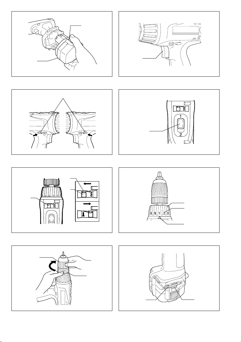
Installing or removing battery cartridge (Fig. 1)
• Always switch off the tool before insertion or removal of
the battery cartridge.
• To remove the battery cartr idge, withdraw it from the
tool while pressing the buttons on both sides of the cartridge.
• To insert the batte ry car tridge, ali gn the tongue on the
battery cartridge with the groove in the housing and slip
it into place. Always insert it all the way until it locks in
place with a little click. If not, it may accidentally fall out
of the tool, causing injur y to you or someone around
you.
• Do not use force when inserting the battery cartridge. If
the cartridge does not slide in easily, it is not being
inserted correctly.
Switch action (F ig. 2)
CAUTION:
Before inserting the battery cartridge into the tool, always
check to see that the switch trigger actuates properly and
returns to the "OFF" pos iti on when rel eas ed.
To start the tool, simply pull the switch trigger. Tool speed
is increased by increasing pressure on the switch trigger.
Release the switch trigger to stop.
Reversing switch action (Fig. 3)
This tool has a reversing switch to change the direction of
rotation. Depress the r eversing switch lever from the A
side for clockwise rotation or from the B side for counte rclockwise rotation.
When the reversing switch lever is in the neutral position,
the switch trigger cannot be pulled.
CAUTION:
• Always check the direction of rotation before operation.
• Use the reversing switch only after the tool comes to a
complete stop. Changing the direction of rotation
before the tool stops may damage the tool.
• When not operating the tool, always set the reversing
switch lever to the neutral position.
Speed change (Fig. 4)
To change the speed, first switch off the tool and then
slide the speed change lever to the "2" side for high
speed or "1" side for low speed. Be sure that the speed
change lever is set to the correct position before operation. Use the right speed for your job.
CAUTION:
• Always set the speed change lever fully to the correct
position. If you operate the tool w ith the speed change
lever positioned halfway between the "1" side and "2"
side, the tool may be damaged.
• Do not use the speed change lever while the tool is running. The tool may be damaged.
Selecting action mode (Fig. 5)
This tool has an mode change lever. For drilling, depress
the lock button and then slid e the action mode change
lever to the left (
action mode change lever to the ri ght (
it is locked. If it is hard to turn the lever, first turn the
chuck slightly in either d irection and then tur n the lever
again.
CAUTION:
• Always slide the action mode change lever all the way
to your desired mode positi on. If you operate the tool
with the
symbols, the tool may be damaged.
• Do not use the action mode change lever while the tool
is running. The tool may be damaged.
Adjusting the fastening torque (Fig. 6)
The fastening torque can be adjusted in 16 steps by turning the adjusting ring so that its graduations are aligned
with the pointer on the tool body.
FIrst, slide the a ction mode change lever to th e position
of
U symbol.
The fastening torque is mini mum when the number 1 is
aligned with the pointer, and maximum when the marking
is aligned with the pointer. The clutch will slip at various
torque levels when set at the number 1 to 16. Before
actual operation, drive a trial screw into your material or a
piece of duplicate material to determine which torque
level is required for a particular application.
CAUTION:
• The adjusting ring d oes not lock when the pointer is
positioned only halfway between the graduations.
f symbol). For screwing, slide the
U symbol) until
lever positioned halfway between the mode
5
Page 6

ASSEMBLY
CAUTION:
Always be sure that the tool is switched off and th e battery cartridge is removed before carrying out any work on
the tool.
Installing or removing driver bit or drill bit (Fig. 7)
Hold the ring and turn the sleeve counterclockwise to
open the chuck jaws. Place the bit i n th e chuck as far as
it will go. Hold the ring firmly and turn the sleeve clockwise to tighten the chuck.
To remove the bit, hold the ring and turn the sleeve counterclockwise.
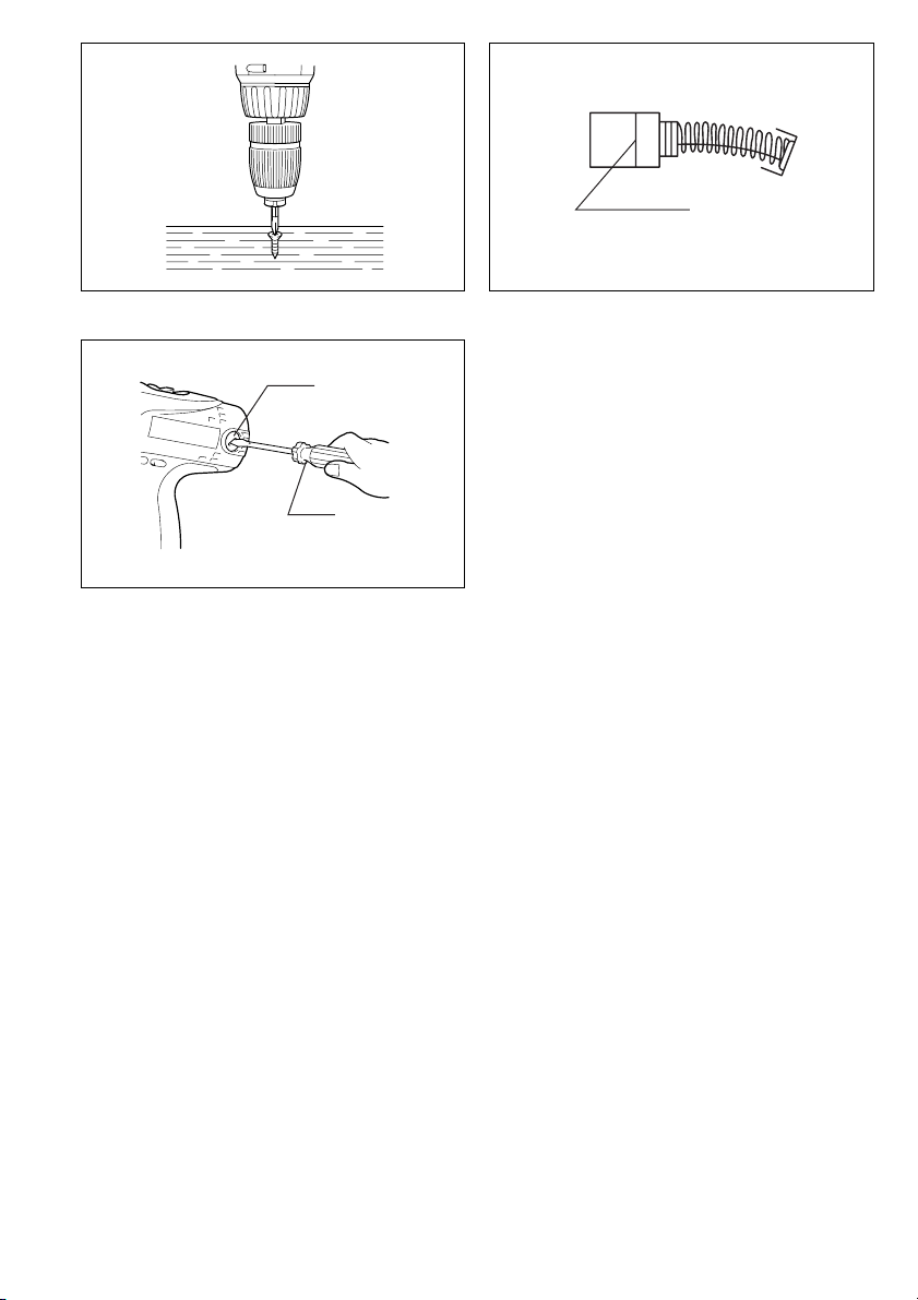
When not using the dri ver bit, keep it in the bit holders.
Bits 45 mm long can be kept there. (Fig. 8)
OPERATION
Screwdriving operation (Fig. 9)
First slide the action mode change lever to the position of
U symbol and select the fastening torque.
Place the point of the dr iver bit in the screw head and
apply pressure to the tool. Star t t he tool slowly and then
increase the speed graduall y. Release the switch trigger
as soon as the clutch cuts in.
CAUTION:
• Make sure that the dr iver bit is insert ed straight in the
screw head, or the screw and/or bit may be damaged.
• When driving wood screws, predrill pilot holes to make
driving easier and to prevent splitting o f the wor kpi ece.
See the chart.
Nominal diameter of wood
screw (mm)
3.1 2.0 – 2.2
3.5 2.2 – 2.5
3.8 2.5 – 2.8
4.5 2.9 – 3.2
4.8 3.1 – 3.4
5.1 3.3 – 3.6
5.5 3.7 – 3.9
5.8 4.0 – 4.2
6.1 4.2 – 4.4
• If the tool is operated continuously until the battery cartridge has discharg ed, al low the tool to res t for 15 minutes before proceeding with a fresh battery.
Drilling operation
First, slide the action mode change lever to the po sition
f symbol.
of
• Drilling in wood
When drilling in wood, the best results are obtained
with wood drills equipped with a guide screw. The
guide screw makes drilling easier by pulling the bit into
the workpiece.
Recommended size of
pilot hole (mm)
• Drilling in metal
To prevent the bit from slipp ing when starting a hole,
make an indentation wit h a center-pun ch and hammer
at the point to be drilled. Place the point of the bit in the
indentation and start drilling. Use a cutting lubricant
when drilling metals. The exceptions are iron and brass
which should be drilled dry.
CAUTION:
• Pressing excessively on the tool will not speed up the
drilling. In fact, this excessive pressure will only serve
to damage the t ip of your bit, decrea se the tool performance and shorte n the service life of the tool.
• There is a tremendous force exerted on the tool/bit at
the time of hole break throu gh. Ho ld the tool fi r mly and
exert care when the bit begins to b reak through the
workpiece.
• A stuck bit can be removed simply by setting the
reversing switch to reverse rotation in order to back out.
However, the tool may back out abruptly if you do not
hold it firmly.
• Always secure small workpieces in a vise or similar
hold-down device.
• If the tool is operated continuously until the battery cartridge has discharg ed, al low the t ool to re st for 15 minutes before proceeding with a fresh battery.
MAINTENANCE
CAUTION:
Always be sure that the tool is switched off an d the battery cartridge is removed before attempting to perform
inspection or maintenan ce.
Replacing carbon brushes
Remove and check the carbon brushes regularly.
Replace when they wear dow n to the limit mark. Keep
the carbon bru shes clean a nd free t o slip in t he hold ers.
Both carbon br ushes should be replaced at the same
time. Use only identical carbon brushes. (Fig. 10)
Use a screwdriver to remove the brush holder caps. Take
out the worn carbon bru shes, insert the new ones and
secure the brush holder caps. (Fig. 11)
To maintain product SAFETY and RELIABILITY, repairs,
any other maintenance or adjustment should be performed by Makita Authorized or Factory Service Centres,
always using Makita replacement parts.
ACCESSORIES
CAUTION:
• These accessories or attachm ents are recommended
for use with your Makita tool specified i n this manual.
The use of any other accessories or attachments might
present a risk of injury to persons. Only use accessory
or attachment for its stated purpose.
If you need any assistance for more details regarding
these accessories, ask your local Makita service center.
• Screw bits
• Rubber pad assembly
• Foam polishing pad 125
• Wool bonnet 100
• Various type of Makita genuine batteries and chargers
• Plastic carrying case
6
Page 7

NEDERLANDS
Verklaring van algemene gegevens
1 Accu
2 Knop
3 Trekschakelaar
4 Omkeerschakelaar
5 Rechtse draairichting
6 Linkse draairichting
7 Toerentalschakelaar
TECHNISCHE GEGEVENS
Model 6207D 6217D 6317D 6337D 6347D
Capaciteiten
Staal ......................................10 mm 10 mm 13 mm 13 mm 13 mm
Hout .......................................25,4 mm 25,4 mm 25,4mm 32 mm 38 mm
Houtschroef ...........................6 x 75 mm 6 x75 mm 6 x 75 mm 6 x 75 mm 10 x 89 mm
Kolomschroef .........................13mm 13 mm 13mm 13mm 13mm
Toerental onbelast (min
Hoog ......................... .............0–1300 0–1300 0–1300 0–1300 0–1300
Laag ..................... .......... ........ 0 – 400 0– 400 0– 400 0– 400 0– 400
Totale lengte .............................233 mm 233 mm 243 mm 243 mm 243 mm
Netto gewicht ............................1,7 kg 1,9 kg 2,0kg 2,1 kg 2,4kg
Nominale spanning ...................D.C . 9,6V D.C. 12V D.C. 12V D.C. 14,4V D.C. 18V
-1
)
8 Werkingskeuzehendel
9 Vergrendelknop
10 Stelring
11 Schaalverdelingen
12 Wijzer
13 Bus
14 Ring
15 Schroefbit
16 Bithouder
17 Limietstreep
18 Borstelhouderdop
19 Schroevendraaier
• In verband met ononderbroken resea rch en ontwikke-
ling behouden wij ons het recht voor bovenstaande
technische gegevens te wijzigen zonder voorafgaande
kennisgeving.
• Opmerking: De technisch e gegevens kunnen van land
tot land verschillen.
Doeleinden van gebruik
Dit gereedschap is bedoeld voor het boren en het
indraaien van schro even in hout, metaal en plastic.
Veiligheidswenken
Voor uw veiligheid dient u de bijgevoegde Veiligheidsvoorschriften nauwkeurig op te volgen.
BELANGRIJKE
VEILIGHEIDSVOORSCHRIFTEN VOOR
ACCULADER EN ACCU
1. Lees alle voorschriften en waarschuwingen op
(1) de acculader, (2) de accu, en (3) het produ ct
waarvoor de accu wordt gebruikt, aandachtig
door alvorens de acculader in gebruik te nemen.
2. Neem de accu niet uit elkaar.
3. Als de gebru ikstijd van een opgeladen accu aan-
zienlijk korter is geworden, moet u het gebruik
ervan onmiddellijk stopzetten. Voortgezet
gebruik kan oververhitting, brandwonden en
zelfs een ontploffing veroorzaken.
4. Als er elektrolyt in uw ogen is t erechtgekomen,
spoel dan uw ogen met schoon water en roep
onmiddellijk de hulp van een dokter in. Elektrolyt
in de ogen kan blindheid veroorzaken.
5. Bedek de accuklemmen altijd met de accukap
wanneer u de ac cu niet gebruikt.
6. Voorkom kortsluiting van de accu:
(1) Raak de accuklemmen nooit aan met een
geleidend materiaal.
(2) Bewaar de accu niet in een bak waarin
andere metalen voorwerpen zoals spijkers,
munten e.d. worden bewaard.
(3) Stel de accu niet bloot aan water of regen.
Kortsluiting van de accu kan oorzaak zijn van
een grote stroomafgifte, oververhitting, brandwonden, en zelfs defecten.
7. Bewaar het gereedschap en de accu niet op
plaatsen waar de temperatuur kan oplopen tot
50°C of hoger.
8. Werp de ac cu noo it i n he t vu ur, ook niet wann ee r
hij zwaar beschadigd of volledig v erslete n is. De
accu kan namelijk ontploffen in het vuur.
9. Wees voorzichtig dat u de accu niet laat vallen
en hem niet blootstelt aan schokken of stoten.
BEWAAR DEZE V OORSCHRIFTEN.
Tips voor een maximale levensduur van de accu
1. Laad de accu op voordat hij volledig ontladen is.
Stop het gebruik van het gereedschap en laad de
accu op telkens w annee r u vaststelt dat het vermogen van het gereedschap is afgenomen.
2. Laad een volledig opgel a den a c cu no oi t opn ieu w
op. Als u de a ccu te vee l oplaadt, zal hij mind er
lang meegaan.
3. Laad de accu op bij een kam ertemperatu ur tussen 10°C en 40°C. Laat een warme accu afkoelen
alvorens hem op te laden.
4. Laad de nikkel-metaalhydride accu op telkens
wanneer u hem langer dan zes maanden niet
hebt gebruikt.
19
Page 8

AANVULLENDE
VEILIGHEIDSVOORSCHRIFTEN
Volg de veiligheidsvoorschriften voor boren ALTIJD
strict op en laat u N I ET m isleiden door gema k o f ve rtrouwdheid met het product (verworven na langdurig
gebruik). Als u dit elektrisch gereedschap op een
onveilige of onjuiste manier gebruikt, bestaat er
gevaar voor ernstige persoonlijke verwon ding.
1. Houd elektrisch g ereedschap vast bij de geïs oleerde handgreepoppervlakken wanneer u een
werk uitvoert waarbij het snijgereedschap met
verborgen bedrading of met zijn eigen netsnoer
in aanraking kan k ome n. D oo r co nt act me t on de r
spanning staande draden zullen de metalen
delen van het gereedschap onder spanning
komen te staan zodat de g ebruiker een elektrische schok kan krijgen.
2. Zorg ervoor dat u altijd stevige steun voor de
voeten hebt.
Controleer of er zich nie m and beneden u bevindt
wanneer u het gereedschap op een hoge plaats
gaat gebruike n .
3. Houd het gereedschap stevig vast.
4. Houd uw handen uit de buurt van de draaiende
onderdelen.
5. Laat het gereed schap niet achte r terwijl het n og
in bedrijf is. Bedien het gereedschap alleen wanneer u het met beide handen vasthoudt.
6. Raak de boor of het werkstuk niet aa n o nmi dd ellijk na het gebruik; deze kunnen erg heet zijn en
brandwonden veroorzak en.
7. Sommige materialen bevatten chemische stoffen
die giftig kunnen zijn. Neem de nodige voorzorgsmaatregelen te gen inademing van stof en
contact met de huid. Volg de veiligheidsinstructies van de leverancier van het materiaal op.
BEWAAR DEZE V OORSCHRIFTEN.
WAARSCHUWING:
VERKEERD GEBRUIK of het niet naleven van de
veiligheidsvoorschriften in deze gebruiksaanwijzing
kan leiden tot ernstige verwondingen.
BEDIENINGSVOORSCHRIFTEN
Installeren of verwijderen van de accu (Fig.1)
• Schakel het gereedschap alt ijd uit alvorens de accu te
installeren of te verwijderen.
• Om de accu te verwijderen, neemt u deze uit het
gereedschap terwijl u de knoppen aan beide zijden van
de accu indrukt.
• Om de accu te installe ren, pa st u de ru g op de a ccu in
de groef in de behuizing van het gereeds chap, en dan
schuift u de accu naar binnen. Schuif de accu zo ver
mogelijk erin, totdat deze met een klikg eluid vergrendelt. Indien u dit niet do et, kan de accu per on gel uk uit
het gereedschap vallen en uzelf of anderen verwonden.
• Als de accu moeilijk in de houder gaat, moet u niet pro-
beren hem met geweld erin te du wen. Indien de accu
er niet gemakkelijk ingaat, betekent dit dat u hem niet
op de juiste wijze erin steekt.
Werking van de trekschakelaar (Fig. 2)
LET OP:
Alvorens de accu in het gereedschap te plaatsen, moet u
altijd controleren of de trekschakelaar juist werkt en bij
het loslaten naar de “OFF” positie terugkeert.
Om het gereedschap in te sch akelen, d r ukt u gewoon de
trekschakelaar in. Hoe dieper de trekschakelaar wordt
ingedrukt, hoe sneller het gereedschap draa it. Om het
gereedschap uit te schakelen, de trekschakelaar loslaten.
Werking van de omkeerschakelaar (Fig.3)
Dit gereedschap heeft een omkeerschakelaar voor het
veranderen van de draairichting. Druk de omkeerschakelaar in vanaf zijde A voor rechtse dra airichting, of vanaf
zijde B voor linkse dra airichting. Wanneer d eze schakelaar in de neutrale stand staat, kan de trekschakelaar niet
worden ingedrukt.
LET OP:
• Controleer altijd de draairichting alvorens het gereedschap te gebruiken.
• Verander de stand van de omkeerschakelaar alleen
nadat het gereedschap volledig tot stilstand is gekomen. Indien u de draairichting verander t terwijl d e boor
nog draait, kan het gereedschap beschadigd raken.
• Zet de omkeerschakelaar altijd in de neutrale stand
wanneer u het gereedschap niet gebruikt.
Veranderen van he t toerental (Fig . 4)
Om het toerental te veranderen, schakelt u eerst het
gereedschap uit en dan schuift u de toerentalschakelaar
naar de “2” zijde voor h oo g to ere nta l, of naa r de “1 ” zi jde
voor laag toerental. Zo rg ervoor da t de toerentalsch akelaar in de juiste stand staat alvorens met het werk te
beginnen. Gebruik het toe rental dat geschikt is voor uw
werk.
LET OP:
• Schuif de toerentalschakelaar altijd volledig naar de
juiste positie. Als u het gereedscha p gebruikt met de
toerentalschakelaar ha lverwege tussen de “1” en “2”
posities, kan het gereedschap besc had igd raken.
• Verschuif de toerentalschakelaar niet terwijl het
gereedschap draait. Hierdoor kan het gereedschap
beschadigd raken.
Kiezen van de gewenste werking (Fig. 5)
Dit gereedschap heeft e en werk ingskeuzehendel . Om te
boren, drukt u de vergrendelknop in en daa rna schuift u
de werkingskeuzehendel naa r links (
te schroeven, schuift u de werkingskeuzehendel naar
rechts (
U symbool) totdat deze vergrendelt. Als de
hendel niet gemakkelijk verschuift, moet u de boorkop
eerst een beetje naar links of naar rechts draaien en
daarna opnieuw prob er en om de hendel te verschuiven.
LET OP:
• Schuif de werki ngskeuzehendel altijd volle dig naar de
gewenste positie. Als u het gereedschap gebruikt met
de werkingskeuzehendel halverwege tussen de twee
symbolen geplaa tst, kan het gere edschap beschadigd
raken.
• Verander de stand van de werkingskeuzehendel niet
terwijl het gereedschap draait. Als u dit doet, kan het
gereedschap beschadigd raken.
f symbool). Om
20
Page 9

Instellen van het draaimoment (Fig.6)
Het draaimoment kan worden ingesteld in 16 stappen
door de stelring zodanig te draaien da t zijn schaalverdelingen overeenkomen met de wijzer op het huis van het
gereedschap.
Schuif eerst de werkingskeuzehendel naar de positie van
U symbool.
het
Het draaimoment is minimaal wanneer het cijfer 1 met de
wijzer overeenkomt, en is maximaal wanneer de markering met de wijzer overeenkomt. Wanneer de stelring op
een cijfer van 1 tot 16 is ing esteld, zal de koppeling bij
verschillende draaimomentniveaus slippen. Alvorens met
het eigenlijke werk te beginnen, moet u het geschikte
draaimoment bepalen d oor een proefschroef in uw werkstuk of in een ander stuk van hetzelfde materiaal te
schroeven.
LET OP:
• De stelring vergrendelt niet wanneer de wijzer halverwege tussen de schaalverdelingen is geplaatst.
INEENZETTEN
LET OP:
Controleer altijd of het ge reedschap is uitgesc hakeld en
de accu is losgekoppeld vooralee r onderh oud uit te voeren aan het gereedschap.
Installeren of verwijderen van de schroefbit of
boor (Fig.7)
Houd de ring vast en draai de bus naar links om de kla uwen van de boorkop te op enen. Steek de boor zo ver
mogelijk in de b oo r kop. Houd daa rna de ring weer stevig
vast en draai de bus naar rechts om de boorkop vast te
zetten.
Om de boor te verwijderen, houdt u de ring vast en draait
u de bus naar links.
Plaats de schroefbi t in de bith ouder wannee r u hem niet
gebruikt. Bits me t een ma ximale le ngte van 45 m m kunnen daar worden opgeborgen. (Fig. 8)
BEDIENING
Indraaien van schroeven (Fig.9)
Schuif eerst de werkingskeuzehendel naar de positie van
U symbool en kies het geschikte draaimoment.
het
Plaats de punt van de schroefbit in de schroefkop en
oefen druk op het geree dschap uit. Be gin met lag e snelheid en voer dan de snelheid geleidelijk op. Laat de trekschakelaar los zodra de koppeling ingrijpt.
LET OP:
• Zorg ervoor dat u de schroefbi t recht op de schroe fkop
plaatst, aangezien anders de schroef en /of de sch ro efbit beschadigd kan worden.
• Wanneer u houtschroeven indraait, maak dan voorboorgaten in het hout. Dit vergemakkelijkt het inschroeven en voorkomt dat het hout splijt. Zie de
onderstaande tabel.
Nominale diameter van
houtschroef (mm)
3,1 2,0–2,2
3,5 2,2–2,5
3,8 2,5–2,8
4,5 2,9–3,2
4,8 3,1–3,4
5,1 3,3–3,6
5,5 3,7–3,9
5,8 4,0–4,2
6,1 4,2–4,4
• Indien het gereedschap ononderbroken wordt
gebruikt totdat d e ac cu i s o ntladen, dient u het geree dschap 15 minuten te laten rusten alvorens met een
nieuwe accu verder te werken.
Aanbevolen diameter
van voorboorgat (mm)
Boren
Schuif eer st de w e rkin g skeuzehend el na ar de po s i ti e v a n
f symbool.
het
• Boren in hout
Voor boren in hout krijgt u de beste resultaten met
houtboren die voorzien zijn van een geleideschroef.
Het boren gaat dan gemakkelijker aangezien de geleideschroef de boor in het hout trekt.
• Boren in metaal
Om te voorkomen dat de boor slipt wanneer u begint te
boren, moet u van te voren met een drevel een deukje
in het metaal slaan op de plaats waar u wilt boren.
Plaats vervolgens de boo rpunt in het deukje en sta rt
het boren. Gebruik altijd boorolie wanneer u in metaal
boort. De enige ui tzonderingen zijn ijzer en koper die
droog geboord dienen te worden.
LET OP:
• Door overmatige druk op het gereedschap uit te oefenen verloopt het boren niet sneller. Integend eel, teveel
druk op het ge reedschap zal a lleen maar de boor punt
beschadigen, de prestatie van het gereedschap verminderen en de gebruiksduur verkorten.
• Wanneer de boor uit het gaatje tevoorschijn komt,
wordt een enorme krach t uitgeoefend op het gereedschap en op de boor. Houd daaro m het gereedschap
stevig vast en wees op uw hoede wanneer de boor
door het werkstuk begint te dringen.
• Wanneer de boor klemraak t, keert u met de omkeerschakelaar de draairichting om, om de boor uit het
gaatje te krijgen . Het gereedschap kan echter plotseling terugspringen indien u het niet stevig vasthoudt.
• Kleine werkstukken dient u altijd eer st vast te zetten in
een klemschroef of iets dergelijks.
• Indien het gereeds chap ononder broken wordt gebr uikt
totdat de accu is ont laden, dient u het gereedschap
15 minuten te laten rusten alvorens met een nieuwe
accu verder te werken.
21
Page 10

ONDERHOUD
LET OP:
Controleer altijd of het g ereedschap is uitge schakeld en
de accu is losgekoppeld voordat u begint met inspectie of
onderhoud.
Vervangen van koolborstels
Verwijder en controleer regelmatig de koolborstels. Vervang de koolborstels wanneer ze to t a an de li mie tma r kering versleten zijn. Hou d de koolborstels schoon, zodat
ze gemakkelijk in de houders glijden. Beide koolborstels
dienen gelijktijdig te worden vervangen. Gebruik uitsluitend gelijksoor tige koolborstels. (Fig. 10)
Gebruik een schroevendraaier om de kappen van de
koolborstelhouders te verwijderen. Haal de versleten
koolborstels eruit, sc huif de nieuwe erin, en zet daarna
de kappen weer goed vast. (Fig. 11)
Om de VEILIGHEID en BETROUWBAARHEID van het
gereedschap te verzekeren, dienen alle reparaties,
onderhoudsbeur ten of afst ellingen te wor den uitgevoerd
bij een erkend Makita S er vice centr um of Fabriekse r vicecentrum, en dit uitslu itend met gebruik van Makita vervangingsonderdelen.
ACCESSOIRES
LET OP:
• Deze accessoires of hulpstukken worde n aanbevolen
voor gebruik met het Makita gereedschap dat in deze
gebruiksaanwijzing is beschreven. Bij gebruik van
andere accessoires of hulpstukken bestaat er gevaar
voor persoonlijke verwonding. Gebruik de accessoires
of hulpstukken uitsluitend voor hun bestemde doel.
Raadpleeg het dichtstbijzijnde Makita Servicecentrum
voor verder advies of bijzonderheden omtrent deze
accessoires.
•Schroefbits
• Rubber steunschijf set
• Schuimrubber polijstkussen 125
• Wollen poetsschijf 100
• Diverse types originele Makita accu’s en acculaders
• Plastic draagkoffer
22
Page 11

ENGLISH
EC-DECLARATION OF CONFORMITY
We declare under our sole responsibility that this product
is in compliance with the following standards of standardized documents,
in accordance with Council Directives, 89/336/EEC and
98/37/EC.
EN60745, EN55014
ENH102-4
ITALIANO
DICHIARAZIONE DI CONFORMITÀ
CON LE NORME DELLA COMUNITÀ EUROPEA
Dichiariamo sotto la nostra sola responsabilità che
questo prodotto è conforme agli standard di documenti
standardizzati seguenti:
secondo le diret tive del Consiglio 89/336/C EE e 98/37/
CE.
EN60745, EN55014
FRANÇAISE
DÉCLARATION DE CONFORMITÉ CE
Nous déclarons sous notre entière responsabilité que ce
produit est conforme aux n ormes des documents standardisés suivants,
conformément aux Directives du Conseil, 89/336/CEE et
98/37/EG.
EN60745, EN55014
DEUTSCH
Hiermit erklärt wir unter unserer alleinigen Verantwortung, daß dieses Produkt ge mäß den Ra tsdirektiven 89/
336/EWG und 98/37/EG m it den folgenden Nor men von
Normendokument en übe rei n stimm en :
CE-KONFORMITÄTSERKLÄRUNG
EN60745, EN55014.
Yasuhiko Kanzaki
NEDERLANDS
EG-VERKLARING VAN CONFORMITEIT
Wij verklaren hierbij uitsluitend op eigen verantwoordelijkheid dat dit produkt voldoet aan de volgende
normen van genormaliseerde documenten,
in overeenstemming met de rich tlijnen van de Raad 89/
336/EEC en 98/37/EC.
EN60745, EN55014
ESPAÑOL
DECLARACIÓN DE CONFORMIDAD DE LA CE
Declaramos bajo nuestra sola responsabilidad que este
producto cumple con las siguientes normas de documentos normalizados,
de acuerdo con la s direc tivas comunitari as, 89/336 /EEC
y 98/37/CE.
CE 2005
EN60745, EN55014
Director Amministratore
Directeur Directeur
Direktor Director
MAKITA INTERNATIONAL EUROPE LTD.
Michigan Drive, Tongwell, Milton Keynes,
Bucks MK15 8JD, ENGLAND
Responsible manufacturer: Produttore responsabile:
Fabricant responsable
Vera ntwortlicher Hersteller: Fabricante responsable:
Makita Corporation Anjo Aichi Japan
: Verantwoordelijk e fabrikant:
47
Page 12

PORTUGUÊS
DECLARAÇÃO DE CONFORMIDADE DA CE
Declaramos sob inteira responsabilidade que este
produto obedece às se guintes normas de documentos
normalizados,
de acordo com as direc tivas 89/336/CEE e 98/37/CE do
Conselho.
EN60745, EN55014
NORSK
ENH102-4
EUs SAMSVARS-ERKLÆRING
erklærer på
Vi
ensstemmelse med følgende standar d i de standardiserte dokumenter:
i samsvar med Råds-direktivene, 89/336/ EEC og 98/37/
EC.
eget ansvar at dette produktet er i over-
EN60745, EN55014,
DANSK
EU-DEKLARATION OM KONFORMITET
Vi erklærer herm ed på eget ansvar, at dette produkt er i
overensstemmelse med de følgende standarder i de
normsættende dokumenter,
i overensstemmelse med Rådet s Direktiver 89/336/EEC
og 98/37/EC.
EN60745, EN55014
SVENSKA
EG-DEKLARATION OM ÖVERENSSTÄMMELSE
Under eget ansvar deklarerar vi härmed att denna
produkt överensstämmer me d följan de standa rdi serin gar
för standardiserade dokument,
i enlighet med EG-direktiven 89/336/EEC och 98/37/EC.
EN60745, EN55014
Yasuhiko Kanzaki
SUOMI
VAKUUTUS EC-VASTAAVUUDESTA
Yksinomaisesti vastuullisina ilmoitamme, että tämä tuote
on seuraavien standardoitujen dokumenttien standardien
mukainen,
neuvoston direktiivien 89/336/EEC ja 98/37/EC mukaisesti.
EN60745, EN55014
ΕΛΛΗΝΙΚΑ
∆ηλώνουµε υπ την µοναδική µας ευθύνη τι αυτ
το προιν βρίσκεται σε Συµφωνία µε τα ακλουθα
πρτυπα τυποποιηµένων εγγράφων,
EN60745, EN55014
σύµφωνα µε τις Οδηγίες του Συµβουλίου, 89/336/
EEC και 98/37/ΚE.
CE 2005
∆ΗΛΩΣΗ ΣΥΜΜΟΡΦΩΣΗΣ ΕΚ
48
Director Direktor
Direktør Johtaja
Direktör ∆ιευθυντής
MAKITA INTERNATIONAL EUROPE LTD.
Michigan Drive, Tongwell, Milton Keynes,
Bucks MK15 8JD, ENGLAND
Fabricante responsável: Ansvarlig produsent:
Ansvarlig fabrikant: Vastaava valmistaja:
Ansvarig tillverkare: Υπεύθυνος κατασκευαστής:
Makita Corporation Anjo Aichi Japan
Page 13

ENGLISH
For European countries only
Noise and Vibration of Model 6207D/6217D
The typical A-weighted sound pressure level is not more
than 70dB (A).
The noise level under working may exceed 85dB (A).
The typical weighted root mean square acceleration
value is not more than 2.5 m/s
These values have been obtained according to
– Wear ear protection. –
2
.
EN60745.
ENG001-2
ITALIANO
Modello per l’E uropa soltanto
Rumore e vibrazione del modello 6207D/6217D
Il livello di pressione sonora pesata seco ndo la cur va A
non supera i 70 dB (A).
Il livello di rumor e duran te il lavoro potre bbe sup erare g li
85dB (A ).
– Indossare i paraorecchi. –
Il valore quadratico medio d i accelle razione no n supera i
2
.
2,5m/s
Questi valori sono stati ottenuti in conformità EN60745.
FRANÇAISE
Pour les pays d’Europe uniquement
Bruit et vibrations du modèle 6207D/6217D
Le niveau de pression sonore pondere type A ne
dépasse pas 70 dB (A).
Le niveau de bruit en fonctionnement peut dépasser
85dB (A).
L’accélération pondérée ne dépasse pas 2,5m/s
Ces valeurs ont été obtenues selon EN60745.
– Porter des protecteurs anti-bruit. –
2
.
DEUTSCH
Nur für europäische Länder
Geräusch- und Vibrationsentwicklung
Der typische A-bewer tete Scha lldru ckpegel beträgt n icht
des Modells
mehr als 70 dB (A).
6207D/6217D
Der Lärmpegel kann während des Betriebs 85 dB (A)
überschreiten.
Der gewichtete Effektivwer t der Besc hleunigung beträgt
nicht mehr als 2,5 m/s
Diese Werte wurden gemäß EN60745 erhalten.
– Gehörschutz tragen. –
2
.
NEDERLANDS
Alleen voor Europese landen
Geluidsniveau e n trilling
van het model
6207D/6217D
Het typische A-gewogen geluid sdrukniveau is niet meer
dan 70 dB (A).
Tijdens het werken kan het geluidsniveau 85dB (A) overschrijden.
De typische gewogen effectieve versnellingswaarde is
niet meer dan 2,5 m/s
Deze waarden werden verkregen in overeenstemming
met EN60745.
– Draag oorbeschermers. –
2
.
ESPAÑOL
Para países europeos solamente
Ruido y vibración del modelo 6207D/6217D
El nivel de presión sonora ponderada A no sobrepasa los
70 dB (A).
El nivel de ruido en c ondiciones de trabajo puede q ue
sobrepase los 85 dB (A).
– Póngase protectores en los oídos. –
El valor ponderado de la aceleración no sobrepasa los
2
.
2,5 m/s
Estos valores han sido obtenidos de acuerdo con
EN60745.
49
Page 14

PORTUGUÊS
Só para países Europeus
Ruído e vibração do modelo 6207D/6217D
O nível normal de pressão sonora A é inferior a
70 dB (A).
O nível de ruído durante o trabalho pode exceder
85dB (A ).
– Utilize protectores para os ouvidos –
O valor médio da aceleração é inferior a 2,5 m/s
Estes valores foram obtidos de acordo com EN60745.
2
.
ENG001-2
NORSK
Gjelder bare land i Europa
Støy og vibrasjon fra modell 6207D/6217D
Det vanlige A-belastede lydtrykksnivå overskrider ikke
70 dB (A).
Under bruk kan støynivået overskride 85dB (A).
Den vanlig belastede effektiv-verdi for akselerasjon overskrider ikke 2,5 m/s
Disse verdiene er beregnet eller målt i samsvar med
– Benytt hørselvern. –
2
.
EN60745.
DANSK
Kun for lande i Europa
Lyd og vibration fra model 6207D/6217D
Det typiske A-vægtede lydtryksniveau overstiger ikke
70 dB (A).
Støjniveauet under arbejde kan overstige 85dB (A).
Den vægtede effektive accelerationsværdi overstiger ikke
2
.
2,5m/s
Disse værdier er beregnet i overensstemmelse med
– Bær høreværn. –
EN60745.
SVENSKA
Endast för Europa
Buller och vibration hos modell 6207D/6217D
Den typiska-A-vägda ljudtrycksnivån överstiger inte
70 dB (A).
Bullernivån under pågående arbete kan överstiga
85dB (A ).
Det typiskt vägda effektivvärdet för acceleration överstiger inte 2,5 m/s
– Använd hörselskydd –
2
.
Dessa värden har erhållits i enlighet med EN60745.
SUOMI
Vain Euroopan maat
Mallin
6207D/6217D melutaso ja tärinä
Tyypillinen A-painotettu äänenpainetaso ei ylitä
70 dB (A).
Melutaso työpaikalla saattaa ylittää 85 dB (A).
– Käytä kuulosuojaimia. –
Tyypillinen kiihtyvyyden painotettu tehollisarvo ei ylitä
2,5m/s2.
Nämä arvot on mitattu normin EN60745 mukaisesti.
ΕΛΛΗΝΙΚΑ
Μ*νο για χώρες της Ευρώπης
Θ*ρυβος και κραδασµ*ς
του µοντέλου 6207D/6217D
Η τυπική Α-µετρούµενη ηχητική πίεση δεν ξεπερνά
τα 70 dB (A).
Η ένταση ήχου υπο συνθήκες εργασίας µπορεί να
µπερβεί τα 85dB (A).
Η τυπική αξία της µετρούµενης ρίζας του µέσου
τετραγώνου της επιτάχυνσης δεν ξεπερνά τα
2,5 m/s
Αυτές οι τιµές έχουν σηµειωθεί σύµφωνα µε το
– Φοράτε ωτοασπίδες. –
2
.
EN60745.
50
Page 15

ENGLISH
For European countries only
Noise and Vibration
The typical A-weighted sound pressure level is 71 dB (A).
Uncertainty is 3 dB (A).
The noise level under working may exceed 85 dB (A).
The typical weighted root mean square acceleration
– Wear ear protection. –
value is not more than 2.5 m/s
These values have been obtained according to
EN60745.
of Model 6317D/6337D
2
.
ENG003-2
ITALIANO
Modello per l’E uropa soltanto
Rumore e vibrazione del modello
Il livello di pressione sonora pesata sec ondo la curva A è
di 71 dB (A) .
L’incertezza è di 3 dB (A).
Il livello di rumor e duran te il lavoro potre bbe sup erare g li
85 dB (A).
– Indossare i paraorecchi. –
Il valore quadratico medio d i accelle razione no n supera i
2
2,5 m/s
.
Questi valori sono stati ottenuti in conformità EN60745.
6317D/6337D
FRANÇAISE
Pour les pays d’Europe uniquement
Bruit et vibrations du modèle
Le niveau de pression sonore pondere type A est de
71 dB (A).
6317D/6337D
L’incertitude de mesure est de 3 dB (A).
Le niveau de bruit en fonctionnement peut dépasser
85 dB (A).
L’accélération pondérée ne dépasse pas 2,5 m/s
– Porter des protecteurs anti-bruit. –
2
.
Ces valeurs ont été obtenues selon EN60745.
DEUTSCH
Nur für europäische Länder
Geräusch- und Vibrationsentwicklung
des Modells
Der typische A-bewertete Schalldruckpegel beträgt
71 dB (A).
Die Abweichung beträgt 3 dB (A).
Der Lärmpegel kann während des Betriebs 85 dB (A)
überschreiten.
– Gehörschutz tragen. –
Der gewichtete Effektivwer t der Besc hleunigung beträgt
nicht mehr als 2,5 m/s
Diese Werte wurden gemäß EN60745 erhalten.
6317D/6337D
2
.
NEDERLANDS
Alleen voor Europese landen
Geluidsniveau en trilling
van het model
6317D/6337D
Het typische A-gewogen geluidsdrukniveau is 71 dB (A).
Onzekerheid is 3 dB (A).
Tijdens het werken kan het geluidsniveau 85 dB (A) overschrijden.
– Draag oorbeschermers. –
De typische gewogen effectieve versnellingswaarde is
niet meer dan 2,5 m/s
2
.
Deze waarden werden verkregen in overeenstemming
met EN60745.
ESPAÑOL
Para países europeos solamente
Ruido y vibración del modelo
El nivel de presión sonora ponderada A es de 71 dB (A).
Incerteza 3 dB (A).
El nivel de ruido en c ondiciones de trabajo puede q ue
sobrepase los 85 dB (A).
– Póngase protectores en los oídos. –
El valor ponderado de la a celeración no sobrepasa los
2
.
2,5 m/s
Estos valores han sido obtenidos de acuerdo con
EN60745.
6317D/6337D
51
Page 16

PORTUGUÊS
Só para países Europeus
Ruído e vibração do modelo
O nível normal de pressão sonora A é 71 dB (A).
A incerteza é de 3 db (A).
O nível de ruído durante o trabalho pode exceder
85 dB (A).
– Utilize protectores para os ouvidos –
O valor médio da aceleração é inferior a 2,5 m/s
Estes valores foram obtidos de acordo com EN60745.
6317D/6337D
2
.
ENG003-2
NORSK
Gjelder bare land i Europa
Støy og vibrasjon fra modell
Det vanlige A-verktet lydtrykksnivå er 71 dB (A).
Usikkerheten er på 3 dB (A).
Under bruk kan støynivået overskride 85 dB (A).
Den typiske vektede effektive akselerasjonsverdi overskrider ikke 2,5 m/s
Disse verdiene er beregnet eller målt i samsvar med
EN60745.
– Benytt hørselvern. –
2
.
6317D/6337D
DANSK
Kun for lande i Europa
Lyd og vibration fra model
Det typiske A-vægtede lydtryksniveau er 71 dB (A).
Der er en usikkerhed på 3 dB (A).
6317D/6337D
Støjniveauet under arbejde kan overstige 85 dB (A).
– Bær høreværn. –
Den vægtede effektive accelerationsværdi overstiger ikke
2
.
2,5m/s
Disse værdier er beregnet i overensstemmelse med
EN60745.
SVENSKA
Endast för Europa
Buller och vibration hos modell
Den typiska-A-vägda ljudtrycksnivån är 71 dB (A).
Osäkerheten är 3 dB (A).
Bullernivån under pågående arbete kan överstiga
85 dB (A).
Det typiskt vägda effektivvärdet för acceleration överstiger inte 2,5 m/s
– Använd hörselskydd –
2
.
Dessa värden har erhållits i enlighet med EN60745.
6317D/6337D
SUOMI
Vain Euroopan maat
Mallin
Tyypillinen A-painotettu äänenpainetaso on 71 dB (A).
Epävarmuus on 3 dB (A).
6317D/6337D melutaso ja tärinä
Melutaso työpaikalla saattaa ylittää 85 dB (A).
– Käytä kuulosuojaimia. –
Tyypillinen kiihtyvyyden painotettu tehollisarvo ei ylitä
2
.
2,5m/s
Nämä arvot on mitattu normin EN60745 mukaisesti.
ΕΛΛΗΝΙΚΑ
Μ*νο για χώρες της Ευρώπης
Θ*ρυβος και κραδασµ*ς
του µοντέλου 6317D/6337D
Η τυπική Α-µετρούµενη ηχητική πίεση είναι
71 dB (A).
Η Αβεβαιτητα είναι 3 dB (A).
Η ένταση ήχου υπο συνθήκες εργασίας µπορεί να
µπερβεί τα 85 dB (A).
– Φοράτε ωτοασπίδες. –
Η τυπική αξία της µετρούµενης ρίζας του µέσου
τετραγώνου της επιτάχυνσης δεν ξεπερνά τα
2
.
2,5 m/s
Αυτές οι τιµές έχουν σηµειωθεί σύµφωνα µε το
ΕΝ60745.
52
Page 17

ENGLISH
For European countries only
Noise and Vibration
The typical A-weighted sound pressure level is 73 dB (A).
Uncertainty is 3 dB (A).
The noise level under working may exceed 85 dB (A).
The typical weighted root mean square acceleration
– Wear ear protection. –
value is not more than 2.5 m/s
These values have been obtained according to
EN60745.
of Model 6347D
2
.
ENG003-2
ITALIANO
Modello per l’E uropa soltanto
Rumore e vibrazione del modello
Il livello di pressione sonora pesata sec ondo la curva A è
di 73 dB (A) .
L’incertezza è di 3 dB (A).
Il livello di rumor e duran te il lavoro potre bbe sup erare g li
85 dB (A).
– Indossare i paraorecchi. –
Il valore quadratico medio d i accelle razione no n supera i
2
2,5 m/s
.
Questi valori sono stati ottenuti in conformità EN60745.
6347D
FRANÇAISE
Pour les pays d’Europe uniquement
Bruit et vibrations du modèle
Le niveau de pression sonore pondere type A est de
73 dB (A).
6347D
L’incertitude de mesure est de 3 dB (A).
Le niveau de bruit en fonctionnement peut dépasser
85 dB (A).
L’accélération pondérée ne dépasse pas 2,5 m/s
– Porter des protecteurs anti-bruit. –
2
.
Ces valeurs ont été obtenues selon EN60745.
DEUTSCH
Nur für europäische Länder
Geräusch- und Vibrationsentwicklung
Der typische A-bewertete Schalldruckpegel beträgt
des Modells
73 dB (A).
Die Abweichung beträgt 3 dB (A).
Der Lärmpegel kann während des Betriebs 85 dB (A)
überschreiten.
Der gewichtete Effektivwer t der Besc hleunigung beträgt
– Gehörschutz tragen. –
nicht mehr als 2,5 m/s
Diese Werte wurden gemäß EN60745 erhalten.
6347D
2
.
NEDERLANDS
Alleen voor Europese landen
Geluidsniveau en trilling van het model
Het typische A-gewogen geluidsdrukniveau is 73 dB (A).
6347D
Onzekerheid is 3 dB (A).
Tijdens het werken kan het geluidsniveau 85 dB (A) overschrijden.
De typische gewogen effectieve versnellingswaarde is
niet meer dan 2,5 m/s
Deze waarden werden verkregen in overeenstemming
– Draag oorbeschermers. –
2
.
met EN60745.
ESPAÑOL
Para países europeos solamente
Ruido y vibración del modelo
El nivel de presión sonora ponderada A es de 73 dB (A).
Incerteza 3 dB (A).
El nivel de ruido en c ondiciones de trabajo puede q ue
sobrepase los 85 dB (A).
– Póngase protectores en los oídos. –
El valor ponderado de la a celeración no sobrepasa los
2
.
2,5 m/s
Estos valores han sido obtenidos de acuerdo con
EN60745.
6347D
53
Page 18

PORTUGUÊS
Só para países Europeus
Ruído e vibração do modelo
O nível normal de pressão sonora A é 73 dB (A).
A incerteza é de 3 db (A).
O nível de ruído durante o trabalho pode exceder
85 dB (A).
– Utilize protectores para os ouvidos –
O valor médio da aceleração é inferior a 2,5 m/s
Estes valores foram obtidos de acordo com EN60745.
6347D
2
.
ENG003-2
NORSK
Gjelder bare land i Europa
Støy og vibrasj on fra modell
Det vanlige A-verktet lydtrykksnivå er 73 dB (A).
Usikkerheten er på 3 dB (A).
Under bruk kan støynivået overskride 85 dB (A).
Den typiske vektede effektive akselerasjonsverdi overskrider ikke 2,5 m/s
Disse verdiene er beregnet eller målt i samsvar med
EN60745.
– Benytt hørselvern. –
2
.
6347D
DANSK
Kun for lande i Europa
Det typiske A-vægtede lydtryksniveau er 73 dB (A).
Lyd og vibration fra model
Der er en usikkerhed på 3 dB (A).
6347D
Støjniveauet under arbejde kan overstige 85 dB (A).
– Bær høreværn. –
Den vægtede effektive accelerationsværdi overstiger ikke
2
.
2,5m/s
Disse værdier er beregnet i overensstemmelse med
EN60745.
SVENSKA
Endast för Europa
Buller och vibration hos modell
Den typiska-A-vägda ljudtrycksnivån är 73 dB (A).
Osäkerheten är 3 dB (A).
Bullernivån under pågående arbete kan överstiga
85 dB (A).
Det typiskt vägda effektivvärdet för acceleration överstiger inte 2,5 m/s
– Använd hörselskydd –
2
.
Dessa värden har erhållits i enlighet med EN60745.
6347D
SUOMI
Vain Euroopan maat
Mallin
Tyypillinen A-painotettu äänenpainetaso on 73 dB (A).
Epävarmuus on 3 dB (A).
6347D melutaso ja tärinä
Melutaso työpaikalla saattaa ylittää 85 dB (A).
– Käytä kuulosuojaimia. –
Tyypillinen kiihtyvyyden painotettu tehollisarvo ei ylitä
2
.
2,5m/s
Nämä arvot on mitattu normin EN60745 mukaisesti.
ΕΛΛΗΝΙΚΑ
Μ*νο για χώρες της Ευρώπης
Θ*ρυβος και κραδασµ*ς
Η τυπική Α-µετρούµενη ηχητική πίεση είναι
73 dB (A).
Η Αβεβαιτητα είναι 3 dB (A).
Η ένταση ήχου υπο συνθήκες εργασίας µπορεί να
µπερβεί τα 85 dB (A).
– Φοράτε ωτοασπίδες. –
Η τυπική αξία της µετρούµενης ρίζας του µέσου
τετραγώνου της επιτάχυνσης δεν ξεπερνά τα
2
.
2,5 m/s
Αυτές οι τιµές έχουν σηµειωθεί σύµφωνα µε το
ΕΝ60745.
του µοντέλου 6347D
54
Page 19

55
Page 20

Makita Corporation
Anjo, Aichi, Japan
884436C996
 Loading...