

Page 1
Models No.
Description
PRODUCT
T
ECHNICAL INFORMATION
CONCEPT AND MAIN APPLICATIONS
P 1/ 7
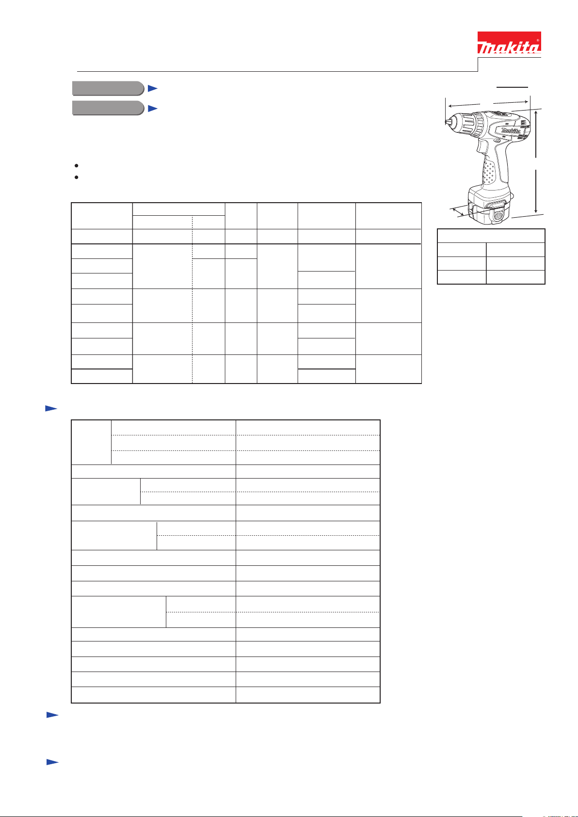
6271D
12V Cordless Driver Drill 10mm (3/8")
L
H
Model 6271D has been developed as the successor model of 6270D, featuring:
Single sleeve keyless drill chuck for easy bit installation/removal
New tool design
W
Dimensions: mm (")
Width (W)
Height (H)
Length (L)
95 (3-3/4)
192 (7-9/16)
240 (9-1/2)
Specification
Battery
Capacity of drill chuck: mm (")
Capacity: mm (")
Lock torque: N.m (in.lbs)
Electric brake
Variable speed control
Mechanical speed control
Reverse switch
Max. fastening
torque: N.m (in.lbs)
Torque setting
Steel
Wood
Soft joint
Hard joint
No load speed:
min-1=rpm
Cell
Voltage: V
Capacity: Ah
High
Net weight [with Battery 1220]: kg (lbs)
Low
Max output: W
Ni-Cd/ Ni-Cd/ Ni-MH
12
1.3/ 2.0/ 2.6
Yes
Yes
Yes (2 speed)
Yes
1.5 (3.3)
10 (3/8)
25 (1)
16 stage + drill mode
Clutch torque setting: N.m (in.lbs) 1.0 - 4.0 (9 - 35)
28 (250)
18 (160)
30 (260)
0 - 1,300
0 - 400
0.8 - 10 (1/32 - 3/8)
165
Also, the models include the accessory listed in "Standard equipment".
Model 6271D is available in the following variations.
6271DZ No
Model No.
type quantity
Charger
---No
Battery
NoNo
6271DW
DC1414
1
No
6271DWAE
DC14142
1222
(Ni-Cd 2.0Ah)
Yes
No
Rechargeable
flashlight
Plastic carrying
case
6271DWE
2
1220
(Ni-Cd 1.3Ah)
Yes
6271DWLE
ML120
6271DWALE ML120
6271DWPE
DC14142
No
6271DWDE
DC1414
1234
(Ni-MH 2.6Ah)
Yes
No
22
6271DWDLE ML120
Battery
cover
1
2
2
2
PA12
(Ni-Cd 1.3Ah)
Yes
No
6271DWPLE ML120
Standard equipment
Note: The standard equipment for the tool shown above may differ by country.
+- Bit 2-65 (double-end) ........ 1 pc
Optional accessories
Charger DC1414
Charger DC1804
Fast charger DC1439
Automotive charger DC1822
Battery 1220
Battery 1222
Battery 1234
Battery 1235
Drill bits for wood
Drill bits for steel
Driver bits
Battery 1235A
Battery PA12
Page 2
P 2/ 7
R
epair
CAUTION: Remove the battery and the bit from the machine for safety before repair/
maintenance in accordance with the instruction manual!
[1] NECESSARY REPAIRING TOOLS
[2] LUBRICATIONS
[3] DISASSEMBLY/ASSEMBLY
[3]-1. Keyless Drill Chuck
Hex wrench 8 Removing / Installing Drill chuck
Plastic hammer Removing Drill chuck
Description Use for
The components of Gear ass’y has been lubricated in Makita plant and assembled under strict quality control. Therefore,
it is recommended to replace Gear ass’y without disassembling in repair.
Note: When replacing Gear ass’y, begin by removing Keyless drill chuck.
As long as the repairing does not concern Gear ass’y, it is not necessary to remove Keyless drill chuck.
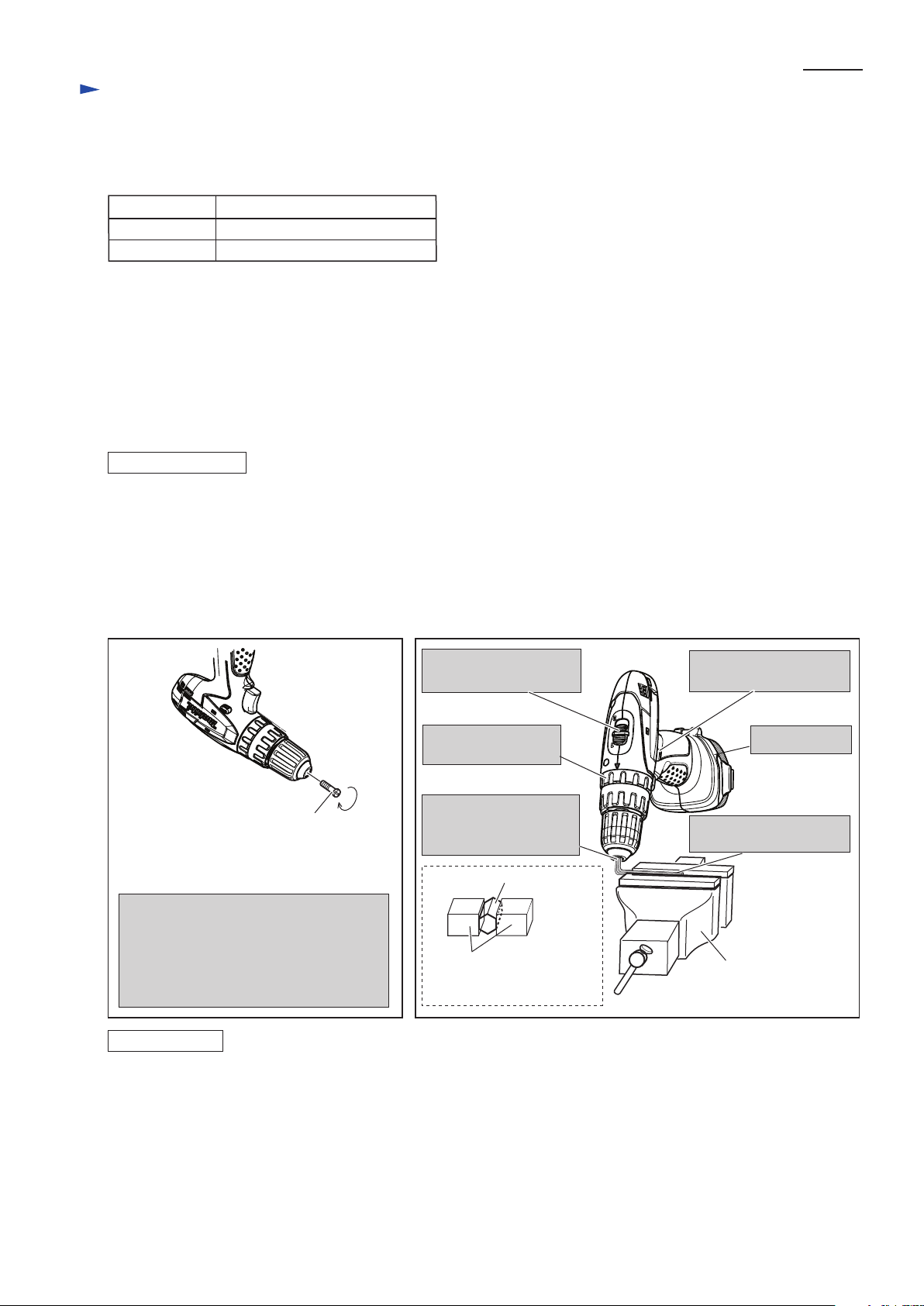
(1) Remove M6x22 Flat head screw. (Fig. 1)
(2) Preset the machine as illustrated in Fig.2.
(3) Hold the machine firmly and pull the switch trigger slowly and carefully.
Note: 1) Pay attention that the machine except Keyless drill chuck starts revolving with strong force. Do not pinch your
hand between the moved machine and Vise in this step.
2) If it is impossible to remove Keyless drill chuck, use 1R359 (Chuck removing tool) to remove it. Refer to Makita
repair tool list.
1) Turn Keyless drill chuck clockwise until it sits on the end of the threaded portion of Spindle.
2) Fix the short portion of Hex wrench 8 to Drill chuck, and clamp the long portion of Hex wrench 8 in Vise.
3) Set Speed change lever in the low speed mode and F/R change lever in the Forward (clockwise) rotation mode. Then
Install Battery.
4) Hold the machine firmly and pull the switch trigger to rotate Spindle until the motor is locked.
Note: Pull the switch trigger so that Spindle reaches full speed in one second.
Important: Be sure to release the switch trigger just after Spindle is locked.
5) Secure Keyless drill chuck with M6x22 Flat head screw by turning counterclockwise with impact driver.
Note: If you reuse the removed M6x22 Flat head screw, apply adhesive (ThreeBond 1321B/ 1342, Loctite 242) to
the threaded portion. Makita genuine M6x22 Flat head screw for securing Keyless drill chuck is threadlocker
screw.
DISASSEMBLING
ASSEMBLING
Hex wrench 8
Note: Hold the flat surface
of Hex wrench 8.
Vise
Clamp the long portion
of Hex wrench 8 in Vise.
Vise
Fig. 1 Fig. 2
M6x22 Flat head screw
with adhesive
Note: Pay attention to the
turning direction.
Open the jaws of Keyless drill chuck fully
and remove M6x22 Flat head screw by
turning clockwise.
If it is difficult to remove the screw with
slotted screwdriver, use cordless impact
driver.
Set F/R Change lever in
the reverse mode.
Set Speed change lever
in the low speed mode.
Set Change ring
in the drill mode.
Hold Hex wrench 8
by tightening the jaws
of Keyless drill chuck.
Install Battery.
Page 3
P 3/ 7
R
epair
[3] DISASSEMBLY/ASSEMBLY
[3]-2. Gear Ass’y, DC Motor
DISASSEMBLING
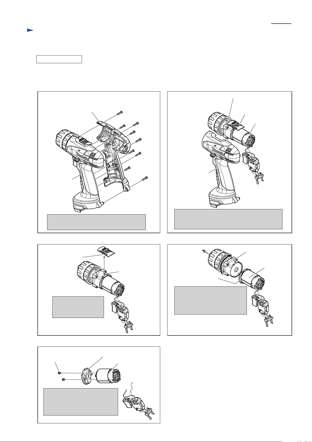
(1) Remove Keyless drill chuck.
(2) Gear ass’y and DC Motor can be disassembled in the order of Figs. 3, 4, 5, 6 and 7.
3x16 Tapping
screw (9pcs.)
Gear ass’y
Speed change lever ass’y
DC motor
Housing set (R)
Housing set (L)
DC motor
notch of Speed
change lever
ass’y
Remove Speed change
lever ass’y from Gear
ass’y.
Gear ass’y
Remove Gear ass’y, Speed change lever ass’y and
DC motor with Switch from Housing set (L) as
illustrated above.
Disassemble Housing set (R) by unscrewing
3x16 Tapping screws (9 pcs.).
Pull off Gear ass’y while turning
it clockwise viewed from DC
motor side.
Now Gear ass’y can be replaced.
Motor bracket
Motor bracket
Remove DC motor from Motor
bracket by unscrewing M3x6
Pan head screws (2pcs.).
Now DC motor can be replaced.
DC motor
Housing set (L)
protrusion of
Gear ass’y
Fig. 3
Fig. 5 Fig. 6
Fig. 7
Fig. 4
M3x6 Pan head
screw (2pcs.)
Page 4

P 4/ 7
R
epair
[3] DISASSEMBLY/ASSEMBLY
[3]-2. Gear Assembly, DC Motor
ASSEMBLING
The following portions of DC motor, Motor bracket and Gear ass’y have to face the same side. (Fig. 8)
* Red point mark (designated as plus terminal) on DC Motor
* None of protrusion side of Motor bracket
* Gear assembly’s protrusion
Do not face the protrusion of
Motor bracket to the protrusion
of Gear ass’y and the red
point mark on DC motor.
Fig. 8
red point mark
on DC motor
Gear ass’y
(1) When assembling Speed change lever ass’y, make sure two Compression springs are assembled to its bottom
in advance. (Fig. 9)
(2) Fit the protrusion of Gear ass’y into Compression spring 4 in Speed change lever ass’y . (Fig. 10)
(3) After mounting, set Speed change lever ass’y to low speed mode or high speed mode. (Fig. 11)
Motor bracket
DC motor
none of protrusion
side
protrusion of Gear ass’y
[3]-3. Speed Change Lever
ASSEMBLING
Compression
spring 4 (2pcs.)
Speed change lever
ass’y
protrusion of Gear ass’y
Fig. 9
Fig. 10
Fig. 11
Speed change
lever ass’y
Slide Speed change lever to either of
the direction designated in arrow, and hold
the position.
1: Low speed mode
2: High speed mode
Page 5

P 5/ 7
R
epair
[3] DISASSEMBLY/ASSEMBLY
[3]-4. Leaf Spring
ASSEMBLING
Fig. 12
Leaf spring
F/R Change Lever
Switch
protrusion
Now F/R change lever is
mounted to Switch.
Fit the protrusion of Switch to the prong
of F/R Change lever.
Prong
Housing set (L)
Before assembling Gear ass’y and DC motor, Leaf spring has to be mounted to Housing set (L) as illustrated in Fig. 12.
F/R Change lever can be assembled to Switch as illustrated in Fig. 13.
ASSEMBLING
Fig. 13
Leaf spring
[3]-5. F/R Change Lever
Switch
Protrusion
F/R Change lever
Page 6

DC Motor
Circuit diagram
P 6/ 7
Red
Color index of lead wires' sheath
Black
Fig. D-1
M2 M1
Lead wires of DC Motor are connected
to Switch as follows.
* Lead wire (red): to Terminal “M1”
* Lead wire (black): to Terminal “M2”
Switch viewed from
Housing set (L) side
Switch viewed from
Housing set (R) side
red point mark
Connecting of Lead Wire (red)
to DC Motor
Connect Lead Wire (red) to
the Terminal marked with
red point mark.
Housing set (R) side
The terminal of this
protruded side is plus.
Switch
Battery holder
Switch
Page 7

Wiring diagram
P 7/ 7
Fig. D-2
Rear view of
Housing set (L)
DC Motor
Switchs’ Lead wires (black, red)
have to be fixed with Lead wire
holder.
DC Motor has to be so
assembled to Housing set (L)
that its Red point mark
is positioned on the back
bone side of the machine.
Front side
Battery holder
Switch’s lead
wire (black)
Switch’s lead
wire (red)
Battery holder
Rear side
Housing set (L)
Housing set (R) Side
This protruded Side is fitted
to Housing set (R).
Front side
Rear side
Switch’s Lead
wire (black)
Switch’s Lead
wire (red)
Fig. D-2A.
Red point
mark
Connect Switch’s Lead wire (black) to
Battery holder while facing it to rear side.
Connect Switch’s Lead wire (red) to
Battery holder while facing it to front side.
 Loading...