

Page 1
Circular Saw
Instruction Manual
Handkreissäge
Betribsanleitung
Piła tarczowa
Instrukcja obsługi
Дисковая пила
Инструкция по эксплуатации
190 mm 5704R
190 mm 5704R
190 mm 5704R190 mm 5704R
Page 2
1
1
2
2
3
3
5
7
4
6
5
6
7
4
8
2
Page 3

8
9
10
9
9
12
13
12
14
1 – 5 mm
11
10
15
8
7
11
13
15
16
21
20
16
12
14
16
17
18
19
3
Page 4
17
18
22
23
19
21
24
20
25
4
Page 5

Symbols
The following show the symbols used for the tool. Be sure that you understand their meaning before use.
Symbole
Die folgenden Symbole werden für die Maschine verwendet. Machen Sie sich vor der Benutzung unbedingt
mit ihrer Bedeutung vertraut.
Symbole
Poniższe symbole używane są do opisu piły. Przed użyciem należy upewnić się, że rozumie się ich znaczenie.
Символы
Следующие объяснения показывают символы, используемые для инструмента. Убедитесь перед
использованием, что Вы понимаете их значение.
❏ Read instruction manual.
❏ Bitte Betriebsanleitung lesen.
❏ Przeczytaj instrukcję obsługi.
❏ Прочитайте инструкцию по эксплуатации.
❏ DOUBLE INSULATION
❏ DOPPELT SCHUTZISOLIERT
❏ PODWÓJNA IZOLACJA
❏ ДВОЙНАЯ ИЗОЛЯЦИЯ
5
Page 6

ENGLISH
Explanation of general view
1 To avoid kickback, do support
board or panel near the cut.
2 Don’t support board or panel
away from the cut.
3 A typical illustration of proper
hand support and workpiece
support.
4 Hex wrench
5Shaft lock
6 Tighten
7 Loosen
8 Saw blade
9 Outer flange
10 Inner flange
11 Hex socket head bolt
12 Setting protuberances
13 Hex socket head bolt
(For adjusting riving knife)
14 Cutting depth
15 Lever
16 Thumb screw
17 For 45°°°° bevel cuts
SPECIFICATIONS
Model 5704R
Blade diameter ............................................. 190 mm
Max. cutting depth
At 90° .......................................................... 66 mm
At 45° .......................................................... 46 mm
No load speed (min
Overall length ............................................... 345 mm
Net weight ....................................................... 4.6 kg
• Due to our continuing program of research and
development, the specifications herein are subject
to change without notice.
• Note: Specifications may differ from country to
country.
Intended use
The tool is intended for performing lengthways and
crossways straight cuts and miter cuts with angles to
45° in wood while in firm contact with the workpiece.
Power supply
The tool should be connected only to a power supply
of the same voltage as indicated on the nameplate,
and can only be operated on single-phase AC supply.
They are double-insulated in accordance with European Standard and can, therefore, also be used from
sockets without earth wire.
-1
) ...................................... 4,900
SAFETY INSTRUCTIONS
Warning! When using electric tools, basic safety
precautions should always be followed to reduce
the risk of fire, electric shock and personal injury,
including the following. Read all these instructions before attempting to operate this product
and save these instructions.
For safe operation:
1. Keep work area clean
Cluttered areas and benches invite injuries.
2. Consider work area environment
Don’t expose power tools to rain. Don’t use
power tools in damp or wet locations. Keep work
area well lit. Don’t use power tools in presence of
flammable liquids or gases.
18 For straight cuts
19 Base plate
20 Lock-off button
21 Switch trigger
22 Vacuum cleaner
23 Limit mark
24 Brush holder cap
25 Screwdriver
3. Guard against electric shock
Prevent body contact with grounded surfaces
(e.g. pipes, radiators, ranges, refrigerators).
4. Keep children away
Do not let visitors contact tool or extension cord.
All visitors should be kept away from work area.
5. Store idle tools
When not in use, tools should be stored in dry,
high, or locked-up place, out of the reach of children.
6. Don’t force tool
It will do the job better and safer at the rate for
which it was intended.
7. Use right tool
Don’t force small tools or attachments to do the
job of a heavy duty tool. Don’t use tools for purposes not intended; for example, don’t use circular saw for cutting tree limbs or logs.
8. Dress properly
Do not wear loose clothing or jewelry. They can
be caught in moving parts. Rubber gloves and
non-skid footwear are recommended when working outdoors. Wear protective hair covering to
contain long hair.
9. Use safety glasses and hearing protection
Also use face or dust mask if cutting operation is
dusty.
10. Connect dust extraction equipment
If devices are provided for the connection of dust
extraction and collection facilities, ensure these
are connected and properly used.
11. Don’t abuse cord
Never carry tool by cord or yank it to disconnect it
from receptacle. Keep cord from heat, oil and
sharp edges.
12. Secure work
Use clamps or a vise to hold work. It’s safer than
using your hand and it frees both hands to operate tool.
13. Don’t overreach
Keep proper footing and balance at all times.
6
Page 7

14. Maintain tools with care
Keep tools sharp and clean for better and safer
performance. Follow instructions for lubricating
and changing accessories. Inspect tool cords
periodically and, if damaged, have repaired by
authorized service facility. Inspect extension
cords periodically and replace if damaged. Keep
handles dry, clean and free from oil and grease.
15. Disconnect tools
When not in use, before servicing, and when
changing accessories such as blades, bits and
cutters.
16. Remove adjusting keys and wrenches
Form the habit of checking to see that keys and
adjusting wrenches are removed from tool before
turning it on.
17. Avoid unintentional starting
Don’t carry plugged-in tool with finger on switch.
Be sure switch is off when plugging in.
18. Outdoor use extension cords
When tool is used outdoors, use only extension
cords intended for use outdoors and so marked.
19. Stay alert
Watch what you are doing. Use common sense.
Do not operate tool when you are tired.
20. Check damaged parts
Before further use of the tool, a guard or other
part that is damaged should be carefully checked
to determine that it will operate properly and perform its intended function. Check for alignment of
moving parts, binding of moving parts, breakage
of parts, mounting, and any other conditions that
may affect its operation. A guard or other part
that is damaged should be properly repaired or
replaced by an authorized service center unless
otherwise indicated elsewhere in this instruction
manual. Have defective switches replaced by
and authorized service center. Do not use tool if
switch does not turn it on and off.
21. Warning
The use of any other accessory or attachment
other than recommended in this operating
instruction or the catalog may present a risk of
personal injury.
22. Have your tool repaired by an expert
This electric appliance is in accordance with the
relevant safety rules. Repairing of electric appliances may be carried out only by experts otherwise it may cause considerable danger for the
user.
ADDITIONAL SAFETY RULES
1. Wear hearing protection.
2. Keep Guards In Place and In Working Order.
Never wedge or tie lower guard open. Check
operation of lower guard before each use.
Don’t use if lower guard does not close
briskly over saw blade.
CAUTION: If saw is dropped, lower guard may
be bent, restricting full return.
3. Do not use blades which are deformed or
cracked.
4. Do not use blades of high speed steel.
5. Do not stop the blades by lateral pressure on
the saw blade.
6. Keep Blades Clean and Sharp. Sharp blades
minimize stalling and kickback.
7. DANGER:
Keep Hands Away From Cutting Area. Keep
hands away from blades. Don’t reach underneath work while blade is rotating. Don’t
attempt to remove cut material when blade is
moving.
CAUTION: Blades coast after turn off.
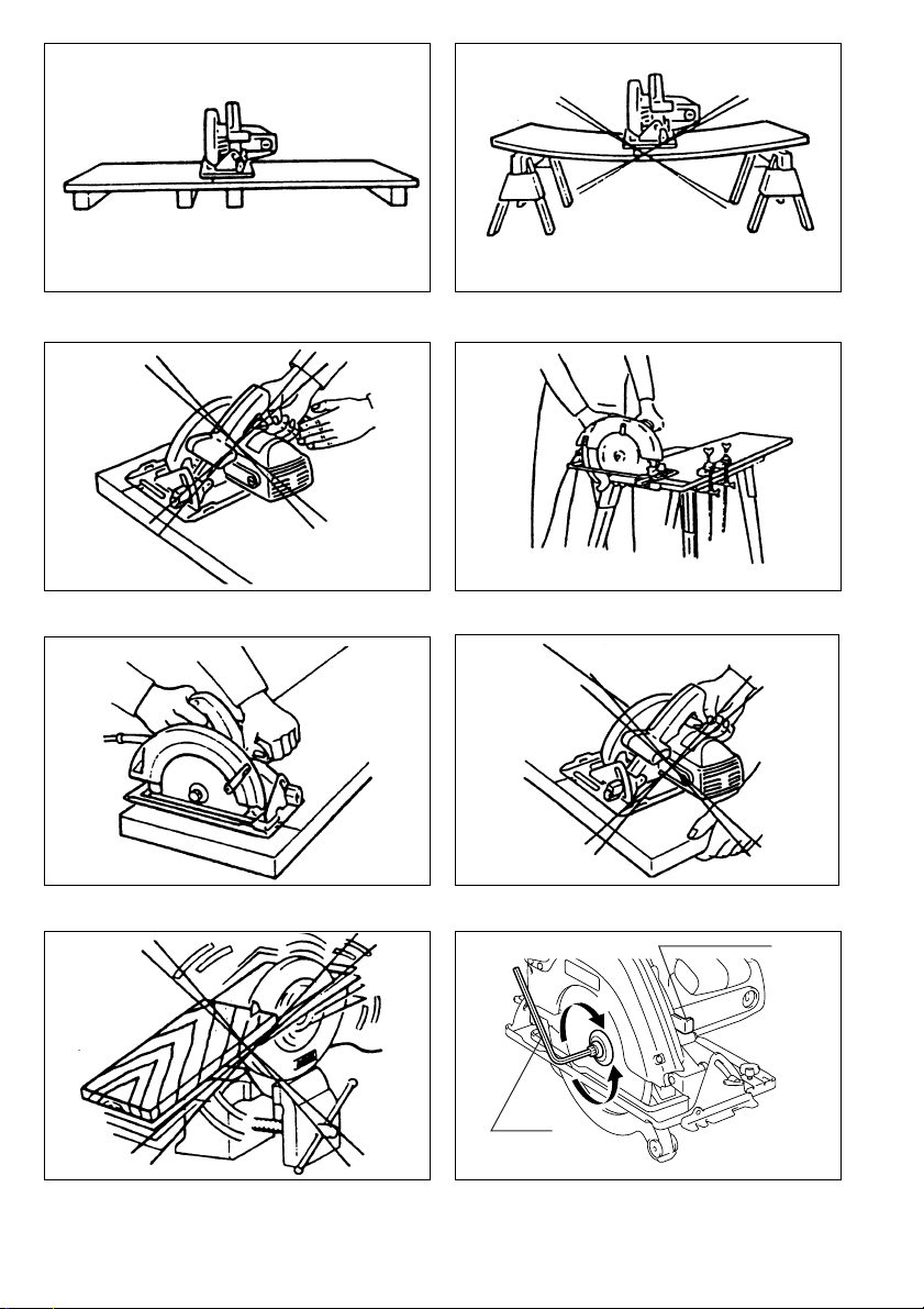
8. Support Large Panels. (Fig. 1 & 2)
Large panels must be supported as shown in
Fig. 1 to minimize the risk of blade pinching
and kickback. When cutting operation
requires the resting of the saw on the workpiece, the saw shall be rested on the larger
portion and the smaller piece cut off.
9. Use Rip Fence.
Always use a fence or straight edge guide
when ripping.
10. Guard Against Kickback. (Fig. 1 & 3)
Kickback occurs when the saw stalls rapidly
and is driven back towards the operator.
Release switch immediately if blade binds or
saw stalls. Keep blades sharp. Support large
panels as shown in Fig.1.
Use fence or straight edge guide when ripping. Don’t force tool. Stay alert – exercise
control. Don’t remove saw from work during a
cut while the blade is moving.
NEVER place your hand or fingers behind the
saw. If kickback occurs, the saw could easily
jump backwards over your hand, possibly
causing severe injury.
11. Lower Guard.
Raise lower guard with the retracting handle.
12. Adjustments.
Before cutting be sure depth and bevel
adjustments are tight.
13. Use Only Correct Blades In Mounting.
Don’t use blades with incorrect size holes.
Never use defective or incorrect blade washers or bolts.
ENB036-2
7
Page 8

14. Avoid Cutting Nails.
Inspect for and remove all nails from lumber
before cutting.
15. When operating the saw, keep the cord away
from the cutting area and position it so that it
will not be caught on the workpiece during
the cutting operation. Operate with proper
hand support, proper workpiece support, and
supply cord routing away from the work area.
WARNING:
It is important to support the workpiece properly and to hold the saw firmly to prevent loss
of control which could cause personal injury.
Fig. 4 illustrates typical hand support of the
saw.
16. Place the wider portion of the saw base on
that part of the workpiece which is solidly
supported, not on the section that will fall off
when the cut is made.
As example, Fig.5 illustrates the RIGHT way
to cut off the end of a board, and Fig.6 the
WRONG way. If the workpiece is short or
small, clamp it down. DON’T TRY TO HOLD
SHORT PIECES BY HAND! (Fig. 6)
17. Never attempt to saw with the circular saw
held upside down in a vise. This is extremely
dangerous and can lead to serious accidents.
(Fig. 7)
18. Before setting the tool down after completing
a cut, be sure that the lower (telescoping)
guard has closed and the blade has come to
a complete stop.
19. Using manufacturer data
• Ensure that the diameter, thickness and
other characteristics of the saw blade are
suitable for the tool.
• Ensure that the saw blade is suitable for the
spindle speed of the tool .
20. Do not use any abrasive wheel.
SAVE THESE INSTRUCTIONS.
OPERATING INSTRUCTIONS
Removing or installing saw blade
The following blade can be used with this tool.
Max.
Min. dia.
dia.
190 mm 170 mm
The thickness of the riving knife is 1.8 mm.
CAUTION:
• Do not use saw blades which do not comply with
the characteristics specified in these instructions.
• Do not use saw blades the disc of which is thicker
or the set of which is smaller than the thickness of
the riving knife.
Hole
dia.
20 mm
30 mm
or
Blade
thick-
ness
Less
than
1.7 mm
Kerf
More
than
1.9 mm
To remove the saw blade, depress the shaft lock fully
to prevent shaft rotation, then use the hex wrench to
loosen the hex socket head bolt. (Fig.8)
Now remove the outer flange, raise the safety cover
as much as possible, and remove the saw blade.
(Fig. 9)
Install the saw blade using the reverse of the removal
procedure. Install the inner flange, saw blade, outer
flange and hex socket head bolt, in that order. Be
sure to secure the hex socket head bolt tightly with
the shaft lock fully depressed. (Fig. 10)
CAUTION:
• Make sure that the blade teeth point forward in the
same direction as the tool rotation (the arrow on the
blade should point in the same direction as the
arrow on the tool).
• The inner flange has a 30 mm diameter on one side
and a 20 mm diameter on the other. The side with
20 mm diameter is marked by “20”. Use the correct
side for the hole diameter of the blade you intend to
use. Mounting the blade on the wrong side can
result in dangerous vibration.
• Use only the Makita hex wrench to remove or install
the blade.
Riving knife adjustment (Fig. 11)
Use the hex wrench to loosen the hex socket head
bolt for the riving knife adjustment, then raise the
safety cover. Move the riving knife up or down over
the two protruberances for settings indicated in the
illustration, so as to obtain the proper clearance
between the riving knife and saw blade.
CAUTION:
Ensure that the riving knife is adjusted such that:
The distance between the riving knife and the
toothed rim of the saw blade is not more than 5mm.
The toothed rim does not extend more than 5mm
beyond the lower edge of the riving knife.
Adjusting depth of cut (Fig. 12)
Loosen the lever on the depth guide and move the
base up or down. At a desired depth of cut, secure
the base by tightening the lever.
CAUTION:
• Use a shallow depth of cut when cutting thin workpiece for cleaner, safer cuts.
• After adjusting the depth of cut, always tighten the
lever securely.
Adjusting for bevel cuts (Fig.13)
Loosen the thumb screws in front and back, and tilt
the tool to the desired angle for bevel cuts (0°–45°).
Secure the thumb screws tightly in front and back
after making the adjustment.
Sighting (Fig.14)
For straight cuts, align the right notch on the front of
the base with your cutting line on the workpiece. For
45° bevel cuts, align the left notch with it.
8
Page 9

Switch action (Fig. 15)
To prevent the switch trigger from being accidentally
pulled, a lock-off button is provided. To start the tool,
depress the lock-off button and pull the switch trigger.
Release the switch trigger to stop.
CAUTION:
Before plugging in the tool, always check to see that
the switch trigger actuates properly and returns to the
“OFF” position when released.
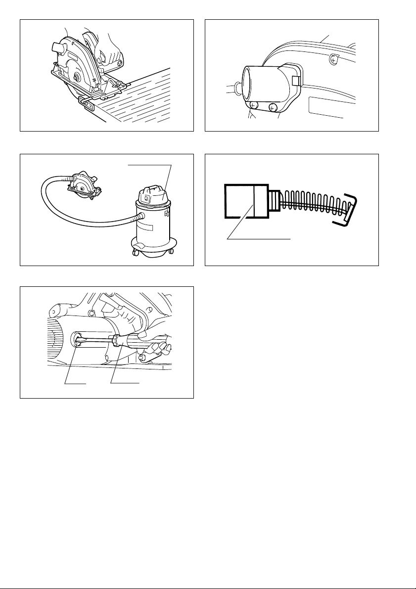
Operation (Fig. 16)
Hold the tool firmly. Set the base plate on the workpiece to be cut without the blade making any contact.
Then turn the tool on and wait until the blade attains
full speed. Now simply move the tool forward over the
workpiece surface, keeping it flat and advancing
smoothly until the sawing is completed. To get clean
cuts, keep your sawing line straight and your speed
of advance uniform.
CAUTION:
• The riving knife should always be used except
when plunging in the middle of the workpiece.
• Do not stop the saw blade by lateral pressure on
the disc.
Guide rule (Fig.17)
The handy guide rule allows you to do extra-accurate
straight cuts. Simply slide the guide rule up snugly
against the side of the workpiece and secure it in
position with the bolt on the front of the base. It also
makes repeated cuts of uniform width possible.
Joint assembly (Fig. 18 &19)
(for connecting a vacuum cleaner)
When you wish to perform clean cutting operation,
connect a vacuum cleaner to your tool. Install the
joint on the tool using the screw. Then connect a
hose of vacuum cleaner to the joint.
MAINTENANCE
CAUTION:
Always be sure that the tool is switched off and
unplugged before carrying out any work on the tool.
Replacement of carbon brushes (Fig. 20 &21)
Replace carbon brushes when they are worn down to
the limit mark. Both identical carbon brushes should
be replaced at the same time.
To maintain product safety and reliability, repairs,
maintenance or adjustment should be carried out by
a Makita Authorized Service Center.
9
Page 10

The typical A-weighted noise levels are
The typical weighted root mean square acceleration value is not more than 2.5 m/s
sound pressure level: 98 dB (A)
sound power level: 111 dB (A)
– Wear ear protection. –
2
.
EC-DECLARATION OF CONFORMITY
We declares that our sole responsibility that this
product is in compliance with the following standards
or standardized documents,
HD400, EN50144, EN55014, EN61000
in accordance with Council Directives, 73/23/EEC,
89/336/EEC and 98/37/EC.
Noise and Vibration
10
Yasuhiko Kanzaki
MAKITA INTERNATIONAL EUROPE LTD
Michigan Drive, Tongwell, Milton Keynes,
Bucks MK15 8JD, ENGLAND
CE 2000
Director
.
Page 11

DEUTSCH
Übersicht
1 Anordnung der Werkstückun-
terlagen zur Vermeidung von
Rückschlag.
2Werkstück nicht zu weit von
der Schnittstelle abstützen.
3 Beispiel der richtigen Hand-
haltung und Abstützung
des Werkstücks.
4 Inbusschlüssel
5 Spindelarretierung
6 Anziehen
7Lösen
8Sägeblatt
9Außenflansch
10 Innenflansch
11 Innensechskantschraube
12 Einstellvorsprünge
13 Innensechskantschraube
(zum Einstellen des Spalt-
keils)
14 Schnittiefe
15 Hebel
TECHNISCHE DATEN
Modell 5704R
Sägeblatt ø .................................................... 190 mm
Max. Schnittiefe
90° ................................................................ 66 mm
45° ................................................................ 46 mm
Leerlaufdrehzahl ................................... 4 900 min
Gesamtlänge ................................................ 345 mm
Nettogewicht .................................................... 4,6 kg
• Wir behalten uns vor, Änderungen im Zuge der Ent-
wicklung und des technischen Fortschritts ohne
vorherige Ankündigung vorzunehmen.
• Hinweis: Die technischen Daten können von Land
zu Land abweichen.
Vorgesehene Verwendung
Das Werkzeug ist für Geradschnitte in Längs- und
Querrichtung sowie für Gehrungsschnitte mit Winkeln bis zu 45° in Holz vorgesehen, wobei es in
festem Kontakt mit dem Werkstück bleibt.
Netzanschluß
Die Maschine darf nur an die auf dem Typenschild
angegebene Netzspannung angeschlossen werden
und arbeitet nur mit Einphasen-Wechselspannung.
Sie ist entsprechend den Europäischen Richtlinien
doppelt schutzisoliert und kann daher auch an Steckdosen ohne Erdanschluß betrieben werden.
SICHERHEITSHINWEISE
Achtung! Beim Gebrauch von Elektrowerkzeugen
sind zum Schutz gegen elektrischen Schlag. Verletzungsund Brandgefahr folgende grundsätzlichen Sicherheitsmaßnahmen zu geachten.
Lesen und beachten Sie diese Hinweise, bevor
Sie das Gerät benutzen.
1. Halten Sie Ihren Arbeitsbereich in Ordnung
Unordnung im Arbeitsbereich ergibt Unfallgefahr.
2. Berücksichtigen Sie Umgebungseinflüsse
Setzen sie Elektrowerkzeuge nicht dem Regen
aus. Benützen Sie Elektrowerkzeuge nicht in
feuchter oder nasser Umgebung. Sorgen Sie für
gute Beleuchtung. Benützen Sie Elektrowerkzeuge nicht in Nähe von brennbaren Flüssigkei-
ten oder Gasen.
16 Rändelschraube
17 Für 45°°°°-Schnitte
18 Für gerade Schnitte
19 Gleitschuh
20 Einschaltsperre
21 Ein-Aus-Schalter
22 Staubsauger
23 Verschleißgrenze
24 Bürstenhalterkappe
25 Schraubendreher
3. Schützen Sie sich vor elektrischem Schlag
Vermeiden Sie Körperberührung mit geerdeten
Teilen, zum Beispiel Rohren, Heizkörpern, Her-
den, kühlschränken.
4. Halten Sie Kinder fern!
Lassen Sie andere Personen nicht das Werk-
-1
zeug oder Kabel berühren, halten Sie sie von
Ihrem Arbeitsbereich fern.
5. Bewahren Sie Ihre Werkzeuge sicher auf
Unbenutzte Werkzeuge sollten in trockenem,
verschlossenem Raum und für Kinder nicht
erreichbar aufbewahrt werden.
6. Überlasten Sie Ihr Werkzeug nicht
Sie arbeiten besser und sicherer im angegebenen Leistungsbereich.
7. Benützen Sie das richtige Werkzeug
Verwenden Sie keine zu schwachen Werkzeuge
oder Vorsatzgeräte für schwere Arbeiten.
Benützen Sie Werkzeuge nicht für Zwecke und
Arbeiten, Wofür sie nicht bestimmt sind; zum
Beispiel benützen Sie keine Handkreissäge, um
Bäume zu flällen oder Äste zu schneiden.
8. Tragen Sie geeignete Arbeitskleidung
Tragen Sie keine weite Kleidung oder Schmuck.
Sie können von beweglichen Teilen erfaßt werden. Bei Arbeiten im Freien sind Gummihandschuhe und rutschfestes Schuhwerk
empfehlenswert. Tragen Sie bei langen Haaren
ein Haarnetz.
9. Schutzbrille und Gehörschutz tragen
Verwenden Sie eine Atemmaske bei stauberzeugenden Arbeiten.
10. Schlleßen Sie eine Staubabsaugvorrichtung
an
Wenn Geräte für den Anschluß von Staubabsaug-und-sammelvorrichtungen ausgelegt sind,
sorgen Sie dafür, daß Jiese angeschlossen und
korrekt benutzi werden.
11. Zweckentfremden Sie nicht das Kabel
Tragen Sie das Werkzeug nicht am Kabel, und
benützen Sie es nicht, um den Stecker aus der
Steckdose zu ziehen. Schützen Sie das Kabel
vor Hitze, Öl und scharfen Kanten.
11
Page 12

12. Sichern Sie das Werkstück
Benützen Sie Spannvorrichtungen oder einen
Schraubstock, um das Werkstück festzuhalten.
Es ist damit sicherer gehalten als mit Ihrer Hand
und ermöglicht die Bedienung der Maschine mit
beiden Händen.
13. Überdehnen Sie nicht Ihren Standbereich
Vermeiden Sie abnormale Körperhaltung. Sorgen Sie für sicheren Stand, und halten Sie jederzeit das Gleichgewicht.
14. Pflegen Sie Ihre Werkzeuge mit Sorgtalt
Halten Sie Ihre Werkzeuge scharf und sauber,
um gut und sicher zu arbeiten. Befolgen Sie die
Wartungsvorschriften und die Hinweise für
Werkzeugwechsel. Kontrollieren Sie regelmäßig
den Stecker und das Kabel, und lassen Sie
diese bei Beschädigung von einem anerkannten
Fachmann erneuern.
Kontrollieren Sie Verlängerungskabel regelmä-
ßig und ersetzen Sie beschädigte. Halten Sie
Handgriffe trocken und frei von Öl und Fett.
15. Ziehen Sie den Netzstecker
Bei Nichtgebrauch, vor der Wartung und beim
Werkzeugwechsel, wie zum Beispiel Sägeblatt,
Bohrer und Maschinenwerkzeugen aller Art.
16. Lassen Sie keine Werkzeugschlüssel stecken
Überprüfen Sie vor dem Einschalten, daß die
Schlüssel und Einstellwerkzeuge entfernt sind.
17. Vermeiden Sie unbeabsichtigten Anlauf
Tragen Sie keine an das Stromnetz angeschlossene Werkzeuge mit dem Finger am Schalter.
Vergewissern Sie sich, daß der Schalter beim
Anschluß an das Stromnetz ausgeschaltet ist.
18. Verlängerungskabel im Freien
Verwenden Sie im Freien nur dafür zugelassene
und entsprechend gekennzeichnete Varlänge-
rungskabel.
19. Seien Sie stets aufmerksam
Beobachten Sie Ihre Arbeit. Gehen Sie vernünf-
tig vor. Verwenden Sie das Werkzeug nicht,
wenn Sie unkonzentriert sind.
20. Kontrollieren Sie Ihr Gerät auf Beschädigungen
Vor weiterem Gebrauch des Werkzeugs die
Schutzeinrichtungen oder leicht beschädigte
Teile sorgfältig auf ihre einwandfreie und bestimmungsgemäße Funktion überprüfen. Überprü-
fen Sie, ob die Funktion beweglicher Teile in
Ordnung ist, ob sie nicht klemmen onder ob Teile
beschädigt sind. Sämtliche Teile müssen richtig
montiert sein und alle Bedingungen erfüllen, um
den einwandfreien Betrieb des Gerätes zu
gewährleisten.
Beschädigte Schutzvorrichtungen und Teile sollen sachgemäß durch eine Kundendienstwerkstatt repariert oder ausgewechselt werden,
soweit nichts anderes in den Betriebsanleitungen angegeben ist. Beschädigte Schalter müs-
sen bei einer Kundendienstwerkstatt ersetzt
werden. Benutzen Sie keine Werkzeuge, bei
denen sich der Schalter nicht ein und ausschalten läßt.
21. Achtung!
Zu Ihrer eigenen Sicherheit, benützen Sie nur
Zubehör und Zusatzgeräte, die in der Bedienungsanleitung angegeben oder vom WerkzeugHersteller empfohlen oder angegeben werden.
Der Gebrauch anderer als der in der Bedienungsanleitung oder im Katalog empfohlenen
Einsatzwerkzeuge oder Zubehöre kann eine persönliche Verletzungsgefahr für Sie bedeuten.
22. Reparaturen nur vom Elektrofachmann.
Dieses Elektrowerkzeug entspricht den einschlä-
gigen Sicherheitsbestimmungen. Reparaturen
dürfen nur von einer Elektrofachkraft ausgeführt
werden, andernfalls können Unfälle für den
Betreiber entstehen.
ZUSÄTZLICHE
SICHERHEITSREGELN
1. Tragen Sie während des Betriebs einen
Augen- oder Gesichtsschutz. Ebenfalls dringend empfohlen ist das Tragen von Gehörschutz, Schutzhandschuhen und
Schutzschuhen. Verwenden Sie eine Atemmaske bei stauberzeugenden Arbeiten.
2. Schutzvorrichtungen vor Inbetriebnahme
überprüfen und nicht entfernen. Die bewegliche Schutzhaube niemals im geöffneten
Zustand verkeilen oder festklemmen. Bewegliche Schutzhaube auf Funktion überprüfen.
3. Nur scharfe Sägeblätter in gutem Zustand
verwenden; gesprungene oder verbogene
Sägeblätter sofort ersetzen.
4. Keine Sägeblätter aus hochlegiertem Schnellarbeitsstahl (HSS) verwenden.
5. Das Sägeblatt nicht durch seitlichen Druck
zum Stillstand bringen.
6. Nur scharfe Sägeblätter in gutem Zustand
verwenden; um ein Einklemmen oder einen
Rückschlag möglichst zu vermeiden.
7. ACHTUNG: Niemals die Schneidezähne
berühren (Verletzungsgefahr). Nicht unter
das Werkstück fassen, während das Sägeblatt läuft. VORSICHT: Sägeblatt läuft nach
dem Abschalten nach.
8. Große Werkstücke müssen in der Nähe des
Schnittes abgestützr werden, um ein Einklemmen des Sägeblatts oder einen
Rücksclag möglichst zu vermeiden.
(Abb. 1 u.2).
Werkstücke nicht in zu großer Entfernung
vom Schnitt abstützen.
9. Bei Längsschnitten immer einen Parallelanschlag oder eine Führungsscheine verwenden.
10. Maschine gegen Rückschlag sichern
(Abb. 1 u.3)
Festklemmen bzw. Verkanten des Sägeblatts
kann zu gefährlichem Rückschlag (Kickback)
der Maschine führen! Schalten Sie die
Maschine sofort ab. Um Rückschlag zu vermeiden,
12
Page 13

1) verwenden Sie nur scharfe HM-Sägeblätter.
2) unterstützen Sie das Werkstück mit
entsprechenden Unterlagen
3) verwenden Sie den Parallelanschlag bei
parallelem Schnittverlauf.
4) Führen Sie die Maschine sicher mit kontrolliertem Druck und unter hoher
Aufmerksamkeit.
5) Heben Sie die Maschine bei laufendem
Sägeblatt nicht aus dem Werkstück.
6) überlasten Sie die Maschine nicht.
Während des Schnittvorgangs niemals die
Hand bzw. Finger hinter der Maschine halten.
Bei Rückschlag der Maschine können schwere Verletzungen verursacht werden.
11. Zum Öffnen der Pendelschutzhaube den
Hebel nach hinten ziehen.
12. Überprüfen Sie vor Arbeitsbeginn die Schnittiefen bzw. Winkeleinstellung.
13. Bei der Montage nur auf die Flanschbohrung
abgestimmte Sägeblätter verwenden.
Keine defekten bzw. vom Original abweichende Flansche, Befestigungsschrauben
oder Unterlegscheiben verwenden.
14. Vor Arbeitsbeginn das Werkstück auf Nägel
o. ä. untersuchen und diese ggf. entfernen.
15. Die Netzanschlußleitung vom Schnittbereich
fernhalten. Achten Sie bei der Verlegung darauf, daß die Netzanschlußleitung nicht
beschädigt wird und den Arbeitsablauf nicht
durch Festklemmen behindert.
Warnung:
Maschine, wie in Abb. 4 gezeigt, immer mit
beiden Händen sicher führen und Werkstück
immer ordnungsgemäß abstützen, um Verletzungen durch unkontrollierte Handhabung zu
vermeiden.
16. Maschine, wie in Abb. 5 gezeigt, mit der großen Auflagefläche der Grundplatte auf das
nicht abzuschneidende Material setzen. Abb.
6 zeigt die falsche Anwendung. Kurze bzw.
kleine Werkstücke müssen während des
Schnittvorgangs festgespannt sein – NIEMALS MIT DER HAND HALTEN! (Abb. 6)
17. Die Handkreissäge ist nur für die handgehaltene Verwendung bestimmt. Spannen Sie die
Maschine nie in einen Schraubstock o. ä. ein
– erhöhte Unfallgefahr! (Abb. 7).
18. Nach dem Bearbeitungsvorgang erst Sägeblatt zum Stillstand kommen lassen, Schutzhaube uaf geschlossene Stellung überprüfen
und danach absetzen.
19. Anhand der Herstellerdaten
• sicherstellen, daß Durchmesser, Dicke und
andere Eigenschaften des Sägeblatts für
die Maschine geeignet sind;
• sicherstellen, daß das Sägeblatt für die
Spindeldrehzahl der Maschine geeignet ist.
20. Verwenden Sie keine Schleifscheiben.
BEWAHREN SIE DIESE HINWEISE
SORGFÄLTIG AUF.
BEDIENUNGSHINWEISE
Montage und Demontage des Sägeblatts
Sägeblätter der folgenden Abmessungen können mit
dieser Maschine verwendet werden.
Max.
Durchm.
190 mm 170 mm
Die Dicke des Spaltkeils beträgt 1,8 mm.
VORSICHT:
• Sägeblätter, die nicht den hier angegebenen Spezifikationen entsprechen, dürfen nicht verwendet
werden.
• Verwenden Sie keine Sägeblätter, deren Dicke größer oder deren Schnittbreite kleiner als die Dicke
des Spaltkeils ist.
Zum Demontieren des Sägeblatts blockieren Sie die
Spindel durch Drücken der Spindelarretierung und
lösen dann die Innensechskantschraube mit dem
Inbusschlüssel. (Abb. 8)
Nun den Außenflansch entfernen, die Schutzhaube
so weit wie möglich anheben, und das Sägeblatt
abnehmen. (Abb. 9)
Zum Montieren des Sägeblatts wenden Sie das
Demontageverfahren umgekehrt an. Montieren Sie
Innenflansch, Sägeblatt, Außenflansch und Innen-
sechskantschraube in dieser Reihenfolge. Ziehen Sie
die Innensechskantschraube bei vollständig hineingedrückter Spindelarretierung fest an. (Abb.10)
VORSICHT:
• Das neue Sägeblatt so montieren, daß die Zähne
nach vorn in Drehrichtung des Sägeblatts zeigen.
Der Drehrichtungssinn der Pfeile von Sägeblatt und
Maschine muß übereinstimmen.
• Der Innenflansch hat einen Durchmesser von
30 mm auf der einen, und von 20 mm auf der anderen Seite. Die Seite mit 20 mm Durchmesser ist mit
“20” markiert. Verwenden Sie die für die Bohrung
des zu benutzenden Sägeblatts passende Seite.
Die Montage des Sägeblatts auf der falschen Seite
kann zu gefährlichen Vibrationen führen.
• Verwenden Sie nur den mitgelieferten MakitaInbusschlüssel zum Demontieren oder Montieren
des Sägeblatts.
Min.
Durchm.
Loch-
durch-
messer.
20 mm
oder
30 mm
Säge-
blattdicke
weniger
als
1,7 mm
Schnitt-
breite
mehr als
1,9 mm
13
Page 14

Einstellung des Spaltkeils (Abb. 11)
Lösen Sie die Innensechskantschraube zur Einstellung des Spaltkeils mit dem Inbusschlüssel, und
heben Sie dann die Schutzhaube an. Bewegen Sie
den Spaltkeil über die zwei Vorsprünge nach oben
oder unten, wie in der Abbildung gezeigt, um den
korrekten Abstand zwischen Spaltkeil und Sägeblatt
zu erzielen.
VORSICHT:
Vergewissern Sie sich, daß der Spaltkeil wie folgt
eingestellt ist: Der Abstand des Spaltkeils zum Zahnkranz des Sägeblatts darf nicht größer als 5mm sein.
Der Zahnkranz darf nicht mehr als 5 mm über die
Unterkante des Spaltkeils überstehen.
Einstellung der Schnitttiefe (Abb. 12)
Lösen Sie den Hebel an der Tiefenführung, und verstellen Sie den Gleitschuh nach oben oder unten.
Arretieren Sie den Gleitschuh an der gewünschten
Schnitttiefe durch Festziehen des Hebels.
VORSICHT:
• Verwenden Sie eine geringe Schnitttiefe für dünne
Werkstücke, um Schnitte von größerer Genauigkeit
und Sicherheit auszuführen.
• Ziehen Sie den Hebel nach der Einstellung der
Schnitttiefe stets fest an.
Einstellung für Neigungsschnitte (Abb.13)
Lösen Sie die Rändelschrauben an der Vorder- und
Rückseite, und neigen Sie das Werkzeug auf den
gewünschten Schnittwinkel (0°– 45°). Ziehen Sie die
Rändelschrauben an der Vorder- und Rückseite nach
der Einstellung wieder fest.
Schnittlinie (Abb. 14)
Für gerade Schnitte richten Sie die rechte Kerbe an
der Vorderseite des Gleitschuhs auf die Schnittlinie
am Werkstück aus. Für Neigungsschnitte von 45°
richten Sie die linke Kerbe auf die Schnittlinie aus.
Schalterbedienung (Abb. 15)
Um versehentliche Betätigung des Ein-Aus-Schalters
zu verhüten, ist die Maschine mit einer Einschaltsperre ausgestattet.
Zum Starten der Maschine betätigen Sie den EinAus-Schalter bei gedrückter Einschaltsperre. Zum
Anhalten lassen Sie den Ein-Aus-Schalter los.
VORSICHT:
Vor dem Anschließen der Maschine an das Stromnetz stets überprüfen, ob der EIN-/AUS-Schalter ordnungsgemäß funktioniert und beim Loslassen in die
AUS- Stellung zurückkehrt.
Betrieb (Abb. 16)
Halten Sie die Maschine mit festem Griff. Setzen Sie
den Gleitschuh auf das zu schneidende Werkstück
auf, ohne daß das Sägeblatt mit ihm in Berührung
kommt. Schalten Sie dann die Maschine ein und warten Sie, bis das Sägeblatt die volle Drehzahl erreicht
hat. Schieben Sie nun die Maschine flach und gleichmäßig über die Oberfläche des Werkstücks vor, bis
der Schnitt vollendet ist. Um saubere Schnitte zu
erzielen, halten Sie eine gerade Schnittlinie und eine
gleichmäßige Vorschubgeschwindigkeit ein.
VORSICHT:
• Der Spaltkeil muß, außer bei Tauchschnitten,
immer ordnungsgemäß montiert sein.
• Bremsen Sie die Maschine nicht durch seitlichen
Druck auf das Sägeblatt ab.
Parallelanschlag (Abb.17)
Der Parallelanschlag ermöglicht gerade Schnitte entlang einer Bezugskante. Dazu mit der Befestigungsschraube den Parallelanschlag in der gewünschten
Einstellung sichern.
Montage des Absaugstutzens (Abb. 18 u. 19)
(zum Anschließen eines Staubsaugers)
Für saubere Sägearbeiten kann ein Absauggerät an
die Handkreissäge angeschlossen werden. Den
Absaugstutzen mit der Schraube an der Handkreissäge befestigen, dann den Schlauch des Absauggerätes an den Absaugstutzen anschließen.
WARTUNG
VORSICHT:
Vor Arbeiten an der Maschine vergewissern Sie sich,
daß sich der Schalter in der “AUS-” Position befindet
und der Netzstecker gezogen ist.
Kohlebürsten wechseln (Abb. 20 u.21)
Kohlebürsten ersetzen, wenn sie bis auf die Verschleißgrenze abgenutzt sind. Beide Kohlebürsten
nur paarweise ersetzen.
Um die Sicherheit und Zuverlässigkeit dieses Gerä-
tes zu gewährleisten, sollten Reparatur-, Wartungs-,
und Einstellarbeiten nur von durch Makita autorisierten Werkstätten oder Kundendienstzentren unter
ausschließlicher Verwendung von Makita-Originalersatzteilen ausgeführt werden.
14
Page 15

Geräusch- und Vibrationsentwicklung
Die typischen A-bewerteten Schalldruckpegel betragen:
Schalldruckpegel: 98 dB (A)
Schalleistungspegel: 111dB (A)
– Gehörschutz tragen. –
Der gewichtete Effektivwert der Beschleunigung beträgt nicht
mehr als 2,5 m/s
2
.
CE-KONFORMITÄTSERKLÄRUNG
Hiermit erklären wir unter unserer alleinigen Verantwortung, dass dieses Produkt gemäß den Ratsdirektiven
73/23EWG, 89/336/EWG und 98/37/EG mit den folgenden
Normen bzw. Normendokumenten übereinstimmt:
HD400, EN50144, EN55014, EN61000.
Yasuhiko Kanzaki
CE 2000
Direktor
MAKITA INTERNATIONAL EUROPE LTD.
Michigan Drive, Tongwell, Milton Keynes,
Bucks MK15 8JD, ENGLAND
15
Page 16

POLSKI
Wyjaśnienia dotyczące piły i jej użycia
1 Aby uniknąć odbić, deskę lub
panel należy podeprzeć
blisko miejsca cięcia.
2 Nie podpieraj deski lub
panelu z dala od miejsca
cięcia.
3 Poprawne trzymanie piły i
zamocowanie przecinanego
elementu.
4 Klucz inbus
5 Blokada wałka
6Zaciśnij
7Zwolnij
8 Tarcza piły
9 Kołnierz zewnętrzny
10 Kołnierz wewnętrzny
11 Śruba z łbem sześciokątnym
12 Karby do ustawień
13 Śruba z łbem sześciokątnym
(Do regulacji klina
rozsyczepiającego)
14 Głębokość cięcia
DANE TECHNICZNE
Model 5704R
Średnica tarczy .............................................190 mm
Maks. głębokość cięcia
Przy 90° ........................................................66 mm
Przy 45° ........................................................46 mm
Prędkość bez obciążenia (min
Całkowita długość ........................................345 mm
Ciężar netto ......................................................4,6 kg
• Ze względu na prowadzony program udoskonaleń i
badań, podane dane techniczne mogą zostać
zmienione bez uprzedzenia.
• Uwaga: Dane techniczne mogą się różnić w
zależności od kraju.
Przeznaczenie
Urządzenie jest przeznaczone do wykonywania
podłużnego i poprzecznego cięcia prostego oraz
cięcia pod kątem do 45°°°° w drewnie, będąc w
trwałym kontakcie z obrabianym przedmiotem.
Zasilanie
Urządzenie to, powinno być podłączone tylko do
źródła zasilania o takim samym napięciu jak
pokazano na tabliczce znamionowej i może być
używane tylko dla zmiennego prądu jednofazowego.
Zgodnie ze standardami Unii Europejskiej
zastosowano podwójną izolację i dlatego też
możliwe jest zasilanie z gniazda bez uziemienia.
-1
) ...................... 4900
INSTRUKCJE BEZPIECZEŃSTWA
Ostrzeżenie! Używając urządzeń elektrycznych
podstawowe środki ostrożności muszą być
zawsze zachowane, aby zmniejszyć ryzyko
ognia, porażenia prądem i uszkodzenia ciała,
włączając poniższe. Przeczytaj wszystkie podane
instrukcje przed próbą użycia tego produktu i
zachowaj je do wglądu.
15 Dźwignia
16 Śruba skrzydełkowa
17 Dla cięcia ukośnego 45°°°°
18 Dla cięcia prostego
19 Płyta podstawy
20 Przycisk blokady wyłączania
21 Język włącznika
22 Odkurzacz
23 Wskaźnik limitu
24 Nasadka szczotki
25 Śrubokręt
Dla bezpiecznego użycia:
1. Utrzymuj miejsce pracy w czystości
Zabałaganione miejsca i stoły warsztatowe
sprzyjają wypadkom.
2. Zastanów się nad warunkami pracy
Nie wystawiaj urządzeń elektrycznych na
deszcz. Nie używaj urządzeń elektrycznych w
wilgotnych lub mokrych miejscach. Utrzymuj
miejsce pracy dobrze oświetlone. Nie używaj
urządzeń elektrycznych w obecności
łatwopalnych płynów lub gazów.
3. Chroń się przed porażeniem prądu.
Zapobiegaj kontaktom ciała z uziemionymi
powierzchniami (np. rurami, grzejnikami,
kuchenkami, lodówkami).
4. Nie pozwalaj zbliżać się dzieciom
Nie pozwalaj wizytującym osobom dotykać
urządzenia lub przedłużacza. Wszystkie
wizytujące osoby nie powinny zbliżać się do
miejsca pracy.
5. Zachowaj nieczynne urządzenia.
Nieużywane urządzenia powinny być
przechowywane w suchych, wysokich lub
zamykanych miejscach tak, aby były
niedostępne dla dzieci.
6. Nie przeciążaj urządzenia.
Wykona ono pracę lepiej i bezpieczniej, pracując
w sposób, dla którego zostało ono
zaprojektowane.
7. Używaj poprawnego urządzenia.
Nie nadużywaj małych lub dodatkowych
urządzeń do wykonania pracy urządzeń do
dużej pracy. Nie używaj urządzeń do celów, do
których nie zostały przeznaczone; na przykład,
nie używaj piły tarczowej do przecinania gałęzi
lub kłód drzew.
8. Ubierz się odpowiednio
Nie noś luźnych ubrań lub biżuterii. Mogą one
zostać zahaczone o ruchome części. Gumowe
rękawiczki i przeciwpoślizgowe buty są
wskazane przy pracy na dworze. Zaleca się
noszenie ochrony na głowę przytrzymującej
długie włosy.
16
Page 17

9. Użyj okularów ochronnych i ochraniaczy
uszu.
Użyj masek na twarz lub masek
przeciwpyłowych jeżeli czynność cięcia
wytwarza pyły.
10. Podłącz urządzenie usuwające pył.
Jeżeli urządzenia posiadają podłączenia do
urządzeń do usuwania i składowania pyłu,
upewnij się, że są one poprawnie podłączone i
użyte.
11. Uważaj na przewód sieciowy
Nigdy nie noś urządzenia trzymając za przewód i
nie odłączaj go od gniazda przez pociągnięcie
przewodu. Chroń przewód przed ciepłem,
olejem i ostrymi krawędziami.
12. Pewnie mocuj cięte elementy.
Użyj ścisków lub imadła do zamocowania
ciętych elementów. Jest to bezpieczniejsze niż
używanie rąk, a dodatkowo zwalnia obie ręce do
obsługiwania piły.
13. Używając piłę, nie oddalaj jej zbytnio od
siebie.
Cały czas trzymaj dobrze ustawione nogi i
równowagę.
14. Pamiętaj o dobrej konserwacji urządzenia.
Utrzymuj urządzenie ostre i czyste dla jego
lepszego i bezpieczniejszego działania. Wykonaj
podane instrukcje w celu smarowania lub
wymiany elementów wyposażenia. Regularnie
sprawdzaj przewody urządzenia, i jeżeli są
uszkodzone, oddaj je do naprawy do
autoryzowanego serwisu. Regularnie sprawdzaj
przewody przedłużające i wymień je, jeżeli są
uszkodzone. Utrzymuj uchwyty suche, czyste i
nie zabrudzone olejem lub smarem.
15. Odłącz urządzenia
Przed konserwacją urządzenia lub zmianą
wyposażenia takiego jak tarcze, noże do struga i
noże do frezowania, gdy nie jest ono używane.
16. Wyjmij klucze regulacyjne
Nabierz zwyczaju sprawdzania czy klucze
regulacyjne są usunięte z urządzenia przed jego
użyciem.
17. Unikaj przypadkowych uruchomień.
Nie noś podłączonego urządzenia z palcem na
włączniku. Upewnij się, że urządzenie jest
wyłączone, gdy je podłączasz do zasilania.
18. Zastosuj przedłużacz używając urządzenia
na dworze.
Gdy urządzenie używane jest na dworze, stosuj
tylko przedłużacze przeznaczone i oznaczone
do pracy na dworze.
19. Bądź uważny
Patrz co robisz. Bądź rozsądny. Nie używaj
urządzenia, gdy jesteś zmęczony.
20. Sprawdzaj uszkodzone części.
Przed dalszym użyciem urządzenia, osłona lub
inne części, które są uszkodzone, muszą być
uważnie sprawdzone, aby upewnić się, że będą
poprawnie działać i wykonywać przeznaczone
im funkcje. Sprawdzaj ustawienia ruchomych
części, oprawy ruchomych części, pęknięcia
części, zamocowania, i jakiekolwiek inne
warunki, które mogą wpływać na działanie.
Osłona lub inne części, które są uszkodzone,
powinny być naprawione lub wymienione przez
autoryzowany serwis, jeżeli w instrukcji nie
podano inaczej. Uszkodzone przełączniki
powinny być wymienione przez autoryzowany
serwis. Nie używaj urządzenia, jeżeli włącznik
nie może go włączyć lub wyłączyć.
21. Ostrzeżenie
Użycie jakiegokolwiek innego wyposażenia lub
części dodatkowych innych niż zalecane w tej
instrukcji obsługi lub katalogu, może stworzyć
ryzyko uszkodzenia ciała.
22. Naprawy urządzenia powinny być
wykonywane tylko przez specjalistę.
To urządzenie jest wykonane zgodnie z
odpowiednimi zasadami bezpieczeństwa.
Naprawa urządzeń elektrycznych może być
wykonana wyłącznie przez specjalistę, gdyż w
przeciwnym wypadku może ono stanowić
zagrożenie dla użytkownika.
DODATKOWE ZASADY
BEZPIECZEŃSTWA
1. Używaj ochraniaczy uszu.
2. Trzymaj osłony na miejscu i w przeznaczony
do pracy sposób. Nigdy nie klinuj lub
przywiązuj dolnej osłony, tak aby była
otwarta. Sprawdzaj działanie dolnej osłony
przed każdym użyciem. Nie używaj
urządzenia, jeżeli dolna osłona nie zamyka
się szybko na tarczy piły. OSTRZEŻENIE:
Jeżeli piła zostanie upuszczona, dolna osłona
może się skrzywić, uniemożliwiając pełne jej
zamknięcie.
3. Nie używaj tarcz, które są zdeformowane lub
popękane.
4. Nie używaj tarcz szybkotnących ze stali
wysokostopwej.
5. Nie zatrzymuj tarcz przez poprzeczny nacisk
na tarczę piły.
6. Utrzymuj tarcze czyste i ostre. Ostre tarcze,
minimalizują zatrzymania silnika i odbicia
piły.
7. NIEBEZPIECZEŃSTWO:
Trzymaj ręce z dala od miejsca cięcia.
Trzymaj ręce z dala od tarczy piły. Nie sięgaj
rękami pod cięty element w trakcie, gdy
tarcza porusza się. Nie próbuj usunąć
odciętego materiału, gdy tarcza porusza się.
OSTRZEŻENIE: Zaraz po wyłączeniu tarcza
obraca się.
1717
Page 18

8. Podparcie dużych paneli. (Rys.1 i 2)
Duże panele muszą być podparte w sposób
pokazany na rysunku. 1 aby zmniejszyć
ryzyko zaklinowania się tarczy i odbić. Gdy
cięcie wymaga oparcia piły na ciętym
elemencie, piła powinna opierać się na
większej części, zaś mniejsza powinna być
odcinana.
9. Użycie prowadnicy cięcia wzdłużnego
Zawsze używaj prowadnicy cięcia
wzdłużnego lub prowadnicy o prostej
krawędzi do prowadzenia piły, gdy
wykonujesz cięcie wzdłużne.
10. Ochrona przed odbiciami. (Rys.1 i 3)
Odbicia pojawiają się, gdy piła jest nagle
zatrzymana i odbija ją w kierunku operatora.
Natychmiast zwolnij włącznik, gdy tarcza
zakleszczy się lub piła zatrzyma się. Utrzymuj
tarcze ostre. Podpieraj duże panele w sposób
pokazany na rys. 1.
Używaj prowadnicy cięcia wzdłużnego lub
prowadnicy o prostej krawędzi do
prowadzenia piły, gdy wykonujesz cięcie
wzdłużne. Nie przeciążaj urządzenia. Bądź
uważny naucz się opanowania. Nie wyjmuj
piły z ciętego elementu w trakcie cięcia, gdy
tarcza porusza się.
NIGDY nie umieszczaj rąk ani palców poza
piłą. Jeżeli wystąpi odbicie, piła może
skoczyć do tyłu nad twoją ręką, mogąc Cię
poważnie ranić.
11. Dolna osłona.
Podnieś dolną osłonę używając uchwytu
samo- powracającego.
12. Ustawienia.
Przed rozpoczęciem cięcia upewnij się, że
głębokość jak i kąt cięcia ukośnego są
pewnie nastawione.
13. W zamocowaniu instaluj tylko odpowiednie
tarcze.
Nie używaj tarcz z nieodpowiednimi
otworami. Nigdy nie używaj uszkodzonych
lub nieodpowiednich śrub ani podkładek do
tarcz.
14. Unikaj cięcia gwoździ.
Sprawdź i usuń wszystkie gwoździe z drzewa
przed cięciem.
15. Trzymaj przewód z dala od miejsca cięcia i
umieść go tak, aby nie został zahaczony
przez cięty element w trakcie używania piły.
Używaj piły stosując jej odpowiednie
trzymanie, odpowiednie podparcie ciętego
elementu i zapewnij miejsce na przewód z
dala od miejsca pracy.
OSTRZEŻENIE:
Ważne jest, aby poprawnie podeprzeć cięty
element i mocno trzymać piłę, aby nie stracić
nad nią kontroli i nie spowodować
uszkodzenia ciała. Rys. 4 pokazuje typowy
sposób trzymania piły.
16. Umieść szerszą część podstawy piły na
części ciętego elementu, który jest mocno
podparty, a nie na części, która spadnie, gdy
cięcie zostanie wykonane.
Jako przykład, rys. 5 pokazuje POPRAWNY
sposób cięcia końca deski, zaś rys. 6
NIEPOPRAWNY sposób. Jeżeli cięty element
jest krótki lub mały, umocuj go ściskami. NIE
WOLNO TRZYMAĆ RĘKĄ KRÓTKICH
ELEMENTÓW! (Rys. 6)
17. Nigdy nie próbuj ciąć piłą tarczową trzymając
ją w imadle do góry nogami. Jest to bardzo
niebezpieczne i może doprowadzić do
ciężkich wypadków. (Rys. 7)
18. Przed położeniem urządzenia po wykonaniu
cięcia, upewnij się, że dolna (teleskopowa)
osłona zamknęła się i, że tarcza zatrzymała
się zupełnie.
19. Użycie danych producenta
• Upewnij się, że średnica, grubość i inne
charakterystyki tarczy są odpowiednie dla
tego urządzenia.
• Upewnij się, że tarcza jest odpowiednia dla
prędkości obrotowej urządzenia.
20. Nie używaj tarczy ściernych.
ZACHOWAJ TÊ INSTRUKCJÊ.
INSTRUKCJA OBSŁUGI
Wyjmowanie i instalowanie tarczy.
Następujące tarcze mogą być użyte w tym
urządzeniu.
Max.
średn.
190 mm 170 mm
Grubość klina rozszczepiającego wynosi 1,8mm.
OSTRZEŻENIE:
• Nie używaj tarcz, które nie spełniają charakterystyk
określonych w tej instrukcji.
• Nie używaj tarcz, których dysk jest grubszy lub,
których zestaw, jest mniejszy niż grubość klina
rozszczepiającego.
Aby wyjąć tarczę, obniż do końca blokadę wałka,
aby zablokować jego obracanie się, a następnie użyj
klucza inubs, aby poluźnić śrubę z łbem
gniazdowym sześciokątnym. (Rys. 8)
Teraz wyjmij kołnierz zewnętrzny, unieś pokrywę
ochronną na tyle na ile jest to możliwe i wyjmij
tarczę. (Rys. 9)
Zainstaluj tarczę wykonując powyższe czynności w
odwrotnej kolejności. W podanej kolejności
zainstaluj kołnierz wewnętrzny, tarczę, kołnierz
zewnętrzny i śrubę z łbem gniazdowym
sześciokątnym. Upewnij się, ze śruba z łbem
gniazdowym sześciokątnym jest mocno przykręcona
pamiętając o pełnym obniżeniu blokady wałka.
(Rys. 10)
Min.
średn.
Średn.
otworu.
20 mm
lub
30 mm
Grubość
tarczy
Mniej
niż
1,7 mm
Nacięcia
Więcej
niż
1,9 mm
1818
Page 19

OSTRZEŻENIE:
• Upewnij się, że zęby tarczy wskazują ten sam
kierunek do przodu co kierunek obracania się
tarczy (strzałka na tarczy powinna wskazywać ten
sam kierunek co strzałka na urządzeniu).
• Kołnierz wewnętrzny ma na jednej stronie średnicę
30mm, a na drugiej 20mm. Strona o średnicy
20 mm jest oznaczona przez “20” . Użyj
poprawnej strony dla średnicy otworu tarczy, którą
chcesz używać. Zamocowanie tarczy na złej
stronie może spowodować niebezpieczne drgania.
• Używaj tylko klucza inbus Makita do wyjmowania i
instalowania tarczy.
Ustawienie klina rozszczepiającego (Rys. 11)
Użyj klucza unbus do poluźnienia śruby z łbem
gniazdowym sześciokątnym a następnie unieś
pokrywę ochronną. Przesuń klin rozszczepiający do
góry lub do dołu nad dwoma karbami, aby wykonać
ustawienia pokazane na ilustracji tak, aby otrzymać
poprawną odległość pomiędzy klinem
rozszczepiającym a tarczą.
OSTRZEŻENIE:
Upewnij się, że klin rozszczepiający jest ustawiony w
taki sposób, że:
Dystans pomiędzy klinem rozszczepiajacym, a
zębatym obrzeżem piły nie jest większy niż 5 mm.
Zębate obrzeże piły nie powinno wychodzić ponad
dolną krawędź klina rozszczepiającego więcej niż
5 mm.
Ustawienie głębokości cięcia (Rys. 12)
Rozluźnij dźwignię w prowadnicy głębokości i
przesuń podstawę do góry lub do dołu. Na żądanej
głębokości cięcia, zamocuj bazę zaciskając
dźwignię.
OSTRZEŻENIE:
• Użyj płytkiej głębokości cięcia przy przecinaniu
cienkich elementów dla czystszego i
bezpieczniejszego cięcia.
• Po ustawieniu głębokości cięcia, zawsze pewnie
zaciśnij dźwignię.
Ustawienie cięcia skośnego (Rys. 13)
Poluźnij śrubę skrzydełkową na przedzie i na tyle i
skręć urządzenie do żądanego kąta cięcia skośnego.
(0°– 45°). Upewnij się, że śruby skrzydełkowe z
przodu i z tyłu są dobrze zakręcone, po wykonaniu
ustawienia.
Celowanie (Rys.14)
Dla prostych cięć, ustaw prawe wycięcie na przedzie
podstawy z linią cięcia na elemencie. Dla cięć
skośnych 45°, ustaw lewe wycięcie.
Funkcje włącznika (Rys. 15)
Aby zapobiec przypadkowemu wysunięciu się
języka włącznika, zainstalowano przycisk blokady
wyłączania. Aby uruchomić urządzenie, naciśnij
przycisk blokady wyłączania i wciśnij język
włącznika. Zwolnij język włącznika, aby zatrzymać
urządzenie.
OSTRZEŻENIE:
Przed podłączeniem urządzenia, zawsze upewnij
się, że język włącznika poprawnie powraca do
pozycji “OFF” (Wył.), gdy zostanie zwolniony.
Obsługa piły (Rys. 16)
Trzymaj piłę pewnie. Ustaw piłę na elemencie do
cięcia tak, aby tarcza nie dotykała elementu.
Następnie włącz urządzenie i zaczekaj dopóki tarcza
nie osiągnie pełnej prędkości. Teraz, przesuń
urządzenie do przodu po powierzchni elementu,
trzymając je płasko i przesuwając płynnie dopóki
cięcie nie zostanie zakończone. Aby uzyskać czyste
cięcie, trzymaj prostą linię cięcia i jednakową
prędkość przesuwania.
OSTRZEŻENIE:
• Klin rozszczepiający powinien być zawsze
używany, z wyjątkiem, gdy piła wprowadzana jest
w środku ciętego elementu.
• Nie zatrzymuj tarczy przez poprzeczny nacisk na
tarczę piły.
Prowadnica krawędziowa (Rys.17)
Poręczna prowadnica krawędziowa umożliwia
bardzo dokładne proste cięcia. Po prostu przesuń
prowadnicę krawędziową dokładnie do strony
ciętego elementu, a następnie umocuj ją w tej
pozycji przy pomocy śruby na przedzie podstawy.
Umożliwia ona również wielokrotne cięcia o tej
samej grubości.
Montaż złącza (Rys.18 i19)
(dla podłączenia odkurzacza)
Gdy wymagane jest czyste cięcie, podłącz
odkurzacz do urządzenia. Zainstaluj złącze w
urządzeniu używając śrubokrętu. Następnie, podłącz
rurę odkurzacza do złącza.
KONSERWACJA
OSTRZEŻENIE:
Zawsze upewnij się, ze urządzenie jest wyłączone i
odłączone od zasilania przed wykonywaniem
jakichkolwiek prac nad urządzeniem.
Wymiana szczoteczek węglowych (Rys. 20i 21)
Wymień szczoteczki węglowe, gdy są starte do
wskaźnika limitu. Dwie takie same szczoteczki
węglowe powinny być wymienione w tym samym
czasie.
Aby zapewnić bezpieczeństwo i niezawodność
produktu, naprawy i konserwacje lub ustawianie
powinno być wykonywane przez autoryzowany
serwis Makita.
1919
Page 20

Typowe A-ważone poziomy szumów
poziom ciśnienia dźwięku: 98 dB (A).
poziom dźwięku w trakcie pracy: 111 dB (A).
Typowa wartość ważonej średniej kwadratowej
przyspieszenia nie jest większa niż 2,5 m/s
- Noś ochraniacze uszu. -
2
.
UE-DEKLARACJA ZGODNOŚCI
Oświadczamy, biorąc za to wyłączną
odpowiedzialność, że niniejszy wyrób jest
zgodny z następującymi standardami i
standardowymi dokumentami:
HD400, EN50144, EN55014, EN61000,
zgodnie z Zaleceniami Rady: 73/23/EEC,
89/336/EEC i 98/37/EC.
Szumy i drgania
Yasuhiko Kanzaki
Dyrektor
MAKITA INTERNATIONAL EUROPE LTD
Michigan Drive, Tongwell, Milton Keynes,
Bucks MK15 8JD, ENGLAND
2020
CE 2000
.
Page 21

РУССКИЙ ЯЗЫК
Объяснения общего плана
1 Во избежание отдачи
закрепите доску или
панель возле резки.
2 Не закрепляйте доску или
панель вдалеке от резки.
3 Типичный рисунок для
правильного упора руки и
крепления рабочего
изделия.
4 Торцовый гаечный ключ
5 Фиксатор оси
6 Завинтите
7 Развинтите
8 Лезвие пилы
9 Внешний фланец
10 Внутренний фланец
11 Болт с шестигранной
головкой
12 Установка выступов
13 Болт с шестигранной
головкой
(Для регулировки
раскалывающего ножа)
14 Глубина резки
ТЕХНИЧЕСКИЕ ХАРАКТЕРИСТИКИ
Модель 5704R
Диаметр лезвия ............................................ 190 мм
Макс. глубина резки
При 90° ......................................................... 66 мм
При 45° ......................................................... 46 мм
Скорость в незагруженном
состоянии (мин
Общая длина ................................................ 345мм
Масса нетто .....................................................4,6 кг
• Вследствие нашей продолжающейся программы
поиска и разработок технические
характеристики могут быть изменены без
уведомления.
• Примечание: Технические характеристики могут
различаться в зависимости от страны.
Предназначенное использование
Этот инструмент предназначен для выполнения
продольной и поперечной прямой резки и
наклонной резки под уголом до 45° в дереве при
плотном контакте с рабочим изделием.
Источник питания
Инструмент должен быть подсоединен только к
источнику питания с напряжением, указанным в
табличке номиналов, и может функционировать
только от однофазного источника питания
переменного тока. В соответствии с Европейским
стандартом имеется двойная изоляция,
следовательно, возможно использование с
розетками без провода заземления.
-1
) .............................................4900
15 Рычаг
16 Винт с накатанной
головкой
17 Для 45°°°° наклонной резки
18 Для прямой резки
19 Опорная плита
20 Кнопка фиксации
21 Пусковой механизм
22 Пылесос
23 Ограничительной метки
24 Крышка держателя щеток
25 Отвертка
ИНСТРУКЦИИ ПО МЕРАМ
БЕЗОПАСНОСТИ
Предостережение! При использовании
электрических инструментов следует всегда
соблюдать основные меры безопасности для
уменьшения опасности пожара, поражения
электрическим током и персональных травм,
включая следующие.
Прочитайте эти инструкции перед тем, как
пытаться управлять этим изделием, и
сохраните эти инструкции.
Для безопасного функционирования:
1. Поддерживайте чистоту на рабочем месте
Захламленные места и подставки могут
привести к травмам.
2. Учитывайте рабочую окружающую среду
Не подвергайте инструменты с
электроприводом воздействию дождя. Не
используйте инструменты с электроприводом в
сырых или влажных местах. Поддерживайте
хорошее освещение на рабочем месте. Не
используйте инструменты с электроприводом в
присутствии возгораемых жидкостей или газов.
3. Предохраняйтесь от поражения
электрическим током
Предотвращайте контакт тела с заземленными
поверхностями (например, трубами,
радиаторами, батареями, холодильниками).
4. Держитесь подальше от детей
Не позволяйте посетителям прикасаться к
инструменту или шнуру-удлинителю. Все
посетители должны находиться подальше от
рабочей области.
5. Правильно храните неработающие
инструменты
Если инструменты не используются, они
должны храниться в сухом, высоком или
закрытом месте, вне достижения детей.
6. Не прилагайте усилие к инструменту
Он будет выполнять работу лучше и
безопаснее при скорости, для которой он
предназначен.
212121
Page 22

7. Используйте правильный инструмент
Не пытайтесь прилагать усилие к маленьким
инструментам или присоединениям для
выполнения работы инструмента тяжелого
назначения. Не используйте инструменты
для непредназначенных целей; например, не
используйте дисковую пилу для резки веток
или корней деревьев.
8. Одевайтесь правильно
Не одевайте свисающую одежду или
украшения. Они могут попасть в движущиеся
части. При работе на улице рекомендуется
одевать резиновые перчатки и нескользящую
обувь. Одевайте предохранительный
головной убор для убирания длинных волос.
9. Используйте защитные очки и
предохранительные приборы для слуха.
Если работа по резке является пыльной,
используйте также маску для лица или
пылезащитную маску
10. Подсоедините пылевсасывающее
оборудование
Если имеются подсоединения устройств для
всасывания и сбора пыли, убедитесь в том,
что они подсоединены и используются
правильно.
11. Не прилагайте усилие к шнуру
Никогда не носите инструмент за шнур и не
дергайте за него для отсоединения его из
розетки. Держите шнур подальше от жарких
мест, масла и острых краев.
12. Закрепите рабочее изделие
Используйте зажимы или тиски для
крепления рабочего изделия. Это является
более безопасным, чем использование
Вашей руки, и при этом освобождаются две
руки для управления инструментом.
13. Не заходите слишком далеко
Сохраняйте правильную стойку и баланс все
время.
14. Осторожно обращайтесь с инструментами
Держите инструменты острыми и чистыми для
более лучшей и безопасной работы. Следуйте
инструкциям для смазки и смены
принадлежностей. Периодически проверяйте
шнуры инструмента, и, если они повреждены,
обращайтесь относительно ремонта в
уполномоченный центр по техобслуживанию.
Периодически проверяйте шнуры-удлинители
и заменяйте, если они повреждены. Держите
ручки сухими чистыми и свободными от масла
или смазки.
15. Отсоединяйте инструменты
Если не используются, перед
техобслуживанием, и при смене
принадлежностей, таких, как лезвия, резцы и
резаки.
16. Убирайте регулировочные ключи и
гаечные ключи
Сформируйте привычку проверять, что
регулировочные ключи и гаечные ключи
убраны с инструмента перед его
включением.
17. Избегайте случайных запусков
Не носите подсоединенный к сети инструмент
с пальцем, находящемся на переключателе.
Перед подсоединением инструмента к сети
убедитесь, что переключатель находится в
положении “выкл”.
18. Шнуры-удлинители для использования на
улице
Когда инструмент используется на улице,
используйте только шнуры-удлинители,
предназначенные для использования на
улице с указанием этого.
19. Будьте бдительны
Наблюдайте за тем, что Вы делаете.
Используйте разумный подход. Не
управляйте инструментом, если Вы устали.
20. Проверяйте поврежденные части
Перед дальнейшим использованием
инструмента, предохранитель или другая
часть должны быть тщательно проверены
для определения того, что они будут
функционировать правильно и выполнять
предназначенную функцию. Проверьте на
предмет совмещения движущихся частей,
соединения движущихся частей, поломки
частей, монтажа и других условий, которые
могут повлиять не их функционирование.
Предохранитель или другая часть должны
быть правильно отремонтированы или
заменены в уполномоченном центре по
техобслуживанию, если только не указано
другое в этой инструкции по эксплуатации.
Дефектные переключатели должны быть
заменены в уполномоченном центре по
техобслуживанию. Не используйте
инструмент, если невозможно его включение
и выключение с помощью переключателя.
21. Предостережение
Использование любой другой принадлежности
или присоединения, отличного от
рекомендуемого в этой инструкции по
эксплуатации или каталоге, может привести к
опасности персональной травмы.
22. Используйте для ремонта услуги
специалиста
Это электрическое оборудование
соответствует относящимся к нему правилам
безопасности. Ремонт электрического
оборудования может проводиться только
специалистами, в противном случае, он может
вызвать существенную опасность для
пользователя.
222222
Page 23

ДОПОЛНИТЕЛЬНЫЕ ПРАВИЛА
БЕЗОПАСНОСТИ
1. Одевайте предохранительные приборы
для слуха.
2. Держите предохранители на месте и в
рабочем порядке.
Никогда не закрепляйте и не
привязывайте нижний предохранитель в
открытом состоянии. Проверяйте работу
нижнего предохранителя перед каждым
использованием. Не используйте, если
нижний предохранитель не закрывается
быстро над лезвием пилы.
ПРЕДУПРЕЖДЕНИЕ: Если Вы уронили
пилу, нижний предохранитель может
изогнуться, затрудняя полные повороты.
3. Не используйте лезвия, которые
деформированы или расколоты.
4. Не используйте лезвия из
высокоскоростной стали.
5. Не останавливайте лезвия путем
горизонтального давления на лезвие
пилы.
6. Держите лезвия чистыми и острыми.
Острые лезвия уменьшают застревание и
отдачу.
7. ОПАСНО:
Держите руки подальше от области резки.
Держите руки подальше от лезвий. Не
касайтесь низа изделя во время вращения
лезвия. Не пытайтесь удалять отрезанный
материал во время движения лезвия.
ПРЕДУПРЕЖДЕНИЕ: Лезвия движутся
после выключения.
8. Закрепите большие панели. (Рис. 1 и 2)
Большие панели должны быть
закреплены, как показано на рис. 1 для
уменьшения опасности прищемления
лезвия и отдачи.
Когда операция резки требует, чтобы пила
находилась на рабочем изделии, пила
должна находиться на большем куске, а
меньший кусок срезается.
9. Используйте разборное заграждение.
Всегда используйте заграждение или
предохранитель с прямыми краями при
продольной резке.
10. Предохранитель против отдачи (Рис. 1 и 3)
Отдача происходит, если пила быстро
застревает и перемещается назад по
направлению к оператору. Если лезвие
изгибается, или пила застревает,
немедленно высвободите переключатель.
Держите лезвия острыми. Закрепите
большие панели, как показано на рис. 1.
Используйте заграждение или
предохранитель с прямыми краями при
продольной резке. Не прикладывайте
усилие к инструменту. Будьте бдительны
– контролируйте работу. Не вынимайте
пилу из изделия во время резки, когда
движется лезвие.
НИКОГДА не помещайте Вашу руку или
пальцы позади пилы. Если произойдет
отдача, пила может легко прыгнуть назад
сверху Вашей руки, причинив, возможно,
тяжелую травму.
11. Нижний предохранитель.
Поднимите нижний предохранитель с
помощью выдвигающейся ручки.
12. Регулировки.
Перед выполнением резки убедитесь в
том, что регулировки глубины и наклона
являются точными.
13. При монтаже используйте только
правильные лезвия.
Не используйте лезвия с неправильным
размером отверстий. Никогда не
используйте дефектные или неправильные
шайбы или болты для лезвий.
14. Избегайте резки гвоздей.
Проверьте наличие и удалите все гвозди
из пиломатериалов перед резкой.
15. Во время управления пилой держите
шнур подальше от области резки и
расположите его так, чтобы он не попал
на рабочее изделие во время операции
резки. Управляйте с правильным упором
руки, правильным креплением рабочего
изделия и шнуром питания, проходящим
подальше от рабочей области.
ПРЕДОСТЕРЕЖЕНИЕ:
Важно правильно закрепить рабочее
изделие и плотно держать пилу для
предотвращения потери контроля,
который может привести к персональной
травме. На рис.4 показан типичный упор
руки на пилу.
16. Разместите более широкий участок основы
пилы на части рабочего изделия, которая
сильно закреплена, а не на секции,
которая упадет после выполнения резки.
Например, на рис. 5 показан ПРАВИЛЬНЫЙ
метод обрезания конца доски, а на рис. 6
показан НЕПРАВИЛЬНЫЙ метод. Если
рабочее изделие является коротким или
маленьким, зажмите его. НЕ ПЫТАЙТЕСЬ
ДЕРЖАТЬ КОРОТКИЕ КУСКИ РУКОЙ!
(Рис. 6)
232323
Page 24

17. Никогда не пытайтесь распиливать
дисковой пилой, держа её вверх дном и в
тисках. Это является очень опасным и
может привести к серьезным
происшествиям. (Рис. 7)
18. Перед снятием инструмента по окончании
резки, следует убедиться, что нижний
(телескопический) предохранитель
закрыт, и лезвие полностью остановлено.
19. Используйте данные производителя
• Убедитесь в том, что диаметр, толщина и
другие характеристики лезвия пилы
являются подходящими для
инструмента.
• Убедитесь в том, что лезвие пилы
является подходящим для скорости
вращения инструмента.
20. Не используйте никакие абразивные
диски.
СОХРАНИТЕ ЭТИ ИНСТРУКЦИИ.
ИНСТРУКЦИЯ ПО ЭКСПЛУАТАЦИИ
Удаление или установка лезвия пилы
С этим инструментом возможно использование
следующего лезвия.
Макс.
диаметр
190 мм 170 мм
Толщина раскалывающего ножа 1,8мм.
ПРЕДУПРЕЖДЕНИЕ:
• Не используйте лезвия пилы, которые не
соответствуют характеристикам, заданным в
этой инструкции.
• Не используйте лезвия пилы, диск которых
толще, или развод которых меньше, чем
толщина раскалывающего ножа.
Для удаления лезвия пилы, высвободите
фиксатор оси полностью для предотвращения
вращения оси, затем используйте торцовый
гаечный ключ для развинчивания болта с
шестигранной головкой. (Рис. 8)
Сейчас удалите внешний фланец, поднимите
защитную крышку, как можно выше, и удалите
лезвие пилы. (Рис.9)
Установите лезвие пилы, используя процедуру,
обратную удалению. Установите внутренний
фланец, лезвие пилы, внешний фланец и болт с
шестигранной головкой, в этом порядке. Следует
надежно зафиксировать болт с шестигранной
головкой. (Рис.10)
Мин.
диаметр
Диаметр
отверстия
20 мм
или
30 мм
Толщин
а лезвия
Менее
чем
1,7 мм
Пропил
Более
чем
1,9 мм
ПРЕДУПРЕЖДЕНИЕ:
• Убедитесь в том, что зубья лезвия направлены
в том же направлении, что и вращение
инструмента (стрелка на лезвии должна быть
направлена в том же направлении, что и
стрелка на инструменте.)
• Внутренний фланец имеет диаметр 30 мм с
одной стороны и диаметр 20 мм с другой.
Сторона с диаметром 20 мм промаркирована
как “20”. Используйте правильную сторону для
диаметра отверстия лезвия, которое Вы
намерены использовать. Монтаж лезвия на
неправильной стороне может привести к
опасной вибрации.
• Используйте только торцовый гаечный ключ
Makita для удаления или установки лезвия.
Регулировка раскалывающего ножа (Рис. 11)
Используйте торцовый гаечный ключ для
развинчивания болта с шестигранной головкой
для регулировки раскалывающего ножа, затем
поднимите защитную крышку. Переместите
раскалывающий нож вверх или вниз над двумя
выступами для установок, указанных на рисунке
так, чтобы получить правильное соответствие
между раскалывающим ножом и лезвием пилы.
ПРЕДУПРЕЖДЕНИЕ:
Убедитесь в том, что раскалывающий нож
подрегулирован так, что:
Расстояние между раскалывающим ножом и
зубчатым краем лезвия пилы составляет не
более чем 5 мм. Зубчатый край не простирается
более чем на 5 мм ниже нижнего края
раскалывающего ножа.
Регулировка глубины резки (Рис.12)
Развинтите рычаг на направляющей глубины и
переместите основу вверх или вниз. На
желаемой глубине резки зафиксируйте основу,
завинтив рычаг.
ПРЕДУПРЕЖДЕНИЕ:
• Используйте небольшую глубину резки при
разрезании тонкого рабочего изделия с целью
более чистой безопасной резки.
• После регулировки глубины резки всегда
надежно завинчивайте рычаг.
Регулировка для наклонной резки (Рис. 13)
Развинтите винты с накатанной головкой
спереди и сзади и наклоните инструмент на
желаемый угол для наклонной резки (0°–45°).
После выполнения регулировки надежно
зафиксируйте винты с накатанной головкой
спереди и сзади.
Визирование (Рис.14)
Для прямой резки совместите правую выемку на
передней стороне основы с Вашей линией резки
на рабочем изделии. Для наклонной резки 45°
совместите с ней левую выемку.
242424
Page 25

Действие переключения (Рис.15)
Для предотвращения случайного нажатия
пускового механизма имеется кнопка фиксации.
Для запуска инструмента высвободите кнопку
фиксации и нажмите пусковой механизм.
Высвободите пусковой механизм для остановки.
ПРЕДУПРЕЖДЕНИЕ:
Перед подсоединением инструмента всегда
проверяйте, чтобы видеть, что пусковой
механизм действует правильно и возвращается в
положение “OFF” (выкл.) при высвобождении.
Управление (Рис. 16)
Держите инструмент крепко. Установите
опорную плиту на рабочее изделие для резки без
контакта с лезвием. Затем включите инструмент
и подождите до тех пор, пока лезвие не наберет
полную скорость. Сейчас просто переместите
инструмент над поверхностью рабочего изделия,
сохраняя его в горизонтальном положении и
продвигая плавно до тех пор, пока не завершено
распиливание. Для получения чистых срезов
сохраняйте прямую линию распиливания и
постоянную скорость продвижения.
ПРЕДУПРЕЖДЕНИЕ:
• Всегда должен использоваться
раскалывающий нож, за исключением
погружения в середину рабочего изделия.
• Не останавливайте лезвие пилы путем
горизонтального давления на диск.
Направляющая линейка (Рис. 17)
Удобная направляющая линейка позволяет Вам
выполнять сверхаккуратные прямые срезы.
Просто сдвиньте направляющую линейку,
прижав её к стороне рабочего изделия и
зафиксируйте её в положении с помощью болта
спереди основы. Это также делает возможным
выполнение повторных одинаковых срезов.
Сборка соединения (Рис. 18 и19)
(для подсоединения пылесоса)
Если Вы хотите выполнить чистую операцию
резки, подсоедините пылесос к Вашему
инструменту. Подсоедините соединение к
инструменту, используя винт. Затем
подсоедините шланг пылесоса к соединению.
ОБСЛУЖИВАНИЕ
ПРЕДУПРЕЖДЕНИЕ:
Всегда проверяйте, что инструмент выключен и
отсоединен перед выполнением любой работы с
инструментом.
Замена угольных щеток (Рис. 20 и21)
Заменяйте угольные щетки, когда они износятся
до предельного значка. Обе одинаковые
угольные щетки следует заменять
одновременно.
Для поддержания безопасности и долговечности
изделия, ремонт, уход и регулировка должна
проводиться в уполномоченном центре по
техобслуживанию Makita.
252525
Page 26

Типичные А-взвешенные уровни шума составляют
уровень звукового давления 98 дБ (А).
уровень звуковой мощности 111 дБ (А).
Типичная взвешенное значение квадратного корня
ускорения составляет не более чем 2,5 м/с
– Надевайте защиту для слуха. –
2
.
ЕС ДЕКЛАРАЦИЯ СООТВЕТСТВИЯ
Мы заявляем под свою собственную
ответственность, что этот продукт находится в
соответствии со следующими стандартами или
документами по стандартизации:
HD400, EN50144, EN55014, EN61000,
согласно сборникам директив 73/23EEC,
89/336/EEC и 98/37EC.
Шум и вибрация
262626
Ясухико Канзаки
Директор
MAKITA INTERNATIONAL EUROPE LTD
Michigan Drive, Tongwell, Milton Keynes,
Bucks MK15 8JD, ENGLAND
CE 2000
.
Page 27

272727
Page 28

Makita Corporation Japan
884378A209
 Loading...