

Makita 5360-21, 5359-21 Operator's Manual
OPERATOR'S MANUAL
MANUEL de L'UTILISATEUR
MANUAL del OPERADOR
Catalog No.
No de Cat.
Catálogo No.
5359-21
5360-21
ROTARY HAMMERS
MARTEAU ROTATIF
MARTILLOS ROTATORIOS
TO REDUCE THE RISK OF INJURY, USER MUST READ AND UNDERSTAND OPERATOR'S MANUAL.
AFIN DE RÉDUIRE LE RISQUE DE BLESSURES, L'UTILISATEUR DOIT LIRE ET BIEN COMPRENDRE LE
MANUEL DE L'UTILISATEUR.
PARA REDUCIR EL RIESGO DE LESIONES, EL USUARIO DEBE LEER Y ENTENDER EL MANUAL DEL
OPERADOR.

GENERAL SAFETY RULES — FOR ALL POWER TOOLS
WARNING!
Failure to follow all instructions listed below may result in electric shock, fire and/or serious injury. The term "power tool" in
all of the warnings listed below refers to your mains-operated (corded) power tool or battery-opearted (cordless) power tool.
WORK AREA SAFETY
1. Keep work area clean and well lit. Cluttered or dark areas invite
accidents.
2. Do not operate power tools in explosive atmospheres, such
as in the presence of flammable liquids, gases, or dust.
Power tools create sparks which may ignite the dust or fumes.
3. Keep children and bystanders away while operating a power
tool. Distractions can cause you to lose control.
ELECTRICAL SAFETY
4. Power tool plugs must match the outlet. Never modify the
plug in any way. Do not use any adapter plugs with earthed
(grounded) power tools. Unmodified plugs and matching outlets
will reduce risk of electric shock.
5. Avoid body contact with earthed or grounded surfaces such
as pipes, radiators, ranges and refrigerators. There is an
increased risk of electric shock if your body is earthed or grounded.
6. Do not expose power tools to rain or wet conditions. Water
entering a power tool will increase the risk of electric shock.
7. Do not abuse the cord. Never use the cord for carrying,
pulling, or unplugging the power tool. Keep cord away from
heat, oil, sharp edges, or moving parts. Damaged or entangled
cords increase the risk of electric shock.
8. When operating a power tool outdoors, use an extension
cord suitable for outdoor use. Use of a cord suitable for outdoor
use reduces the risk of electric shock.
PERSONAL SAFETY
9. Stay alert, watch what you are doing and use common sense
when operating a power tool. Do not use a power tool while
you are tired or under the influence of drugs, alcohol or
medication. A moment of inattention while operating power tools
may result in serious personal injury.
10. Use safety equipment. Always wear eye protection. Safety
equipment such as dust mask, non-skid safety shoes, hard hat, or
hearing protection used for appropriate conditions will reduce personal injuries.
11. Avoid accidental starting. Ensure the switch is in the off-
position before plugging in. Carrying tools with your finger on
the switch or plugging in power tools that have the switch on invites
accidents.
12. Remove any adjusting key or wrench before turning the
power tool on. A wrench or a key left attached to a rotating part of
the power tool may result in personal injury.
13. Do not overreach. Keep proper footing and balance at all
times. This enables better control of the power tool in unexpected
situations.
14. Dress properly. Do not wear loose clothing or jewellery.
Keep your hair, clothing and gloves away from moving parts.
Loose clothes, jewellery, or long hair can be caught in moving parts.
15. If devices are provided for the connection of dust extrac-
tion and collection facilities, ensure these are connected
and properly used. Use of these devices can reduce dust-re-
lated hazards.
page 2
READ ALL INSTRUCTIONS
SA VE THESE INSTRUCTIONS
POWER TOOL USE AND CARE
16. Do not force the power tool. Use the correct power tool for
your application. The correct power tool will do the job better and
safer at the rate for which it was designed.
17. Do not use the power tool if the switch does not turn it on
and off. Any power tool that cannot be controlled with the switch is
dangerous and must be repaired.
18. Disconnect the plug from the power source and/or the bat-
tery pack from the power tool before making any adjustments, changing accessories, or storing power tools. Such
preventive safety measures reduce the risk of starting the tool accidentally.
19. Store idle power tools out of the reach of children and do
not allow persons unfamiliar with the power tools or these
instructions to operate power tools. Power tools are danger-
ous in the hands of untrained users.
20. Maintain power tools. Check for misalignment or binding of
moving parts, breakage of parts and any other condition
that may affect the power tool's operation. If damaged, have
the power tool repaired before use. Many accidents are caused
by poorly maintained power tools.
21. Keep cutting tools sharp and clean. Properly maintained cutting
tools with sharp cutting edges are less likely to bind and are easier
to control.
22. Use the power tool, accessories and tool bits etc., in accor-
dance with these instructions and in the manner intended
for the particular type of power tool, taking into account the
working conditions and the work to be performed. Use of
the power tool for operations different from those intended could
result in a hazardous situation.
SERVICE
23. Have your power tool serviced by a qualified repair person
using only identical replacement parts. This will ensure that
the safety of the power tool is maintained.
SPECIFIC SAFETY RULES
1. Hold power tools by insulated gripping surfaces when performing an operation where the cutting tool may contact hidden
wiring or its own cord. Contact with a "live" wire will make exposed metal parts of the tool "live" and shock the operator.
2. Wear ear protectors. Exposure to noise can cause hearing loss.
3. Keep hands away from all cutting edges and moving parts.
4. Use auxiliary handles supplied with the tool. Loss of control can cause personal injury.
5. Maintain labels and nameplates. These carry important information. If unreadable or missing, contact a MILWAUKEE Service facility for a
free replacement.
6. WARNING! Some dust created by power sanding, sawing, grinding, drilling, and other construction activities contains chemicals known to cause
cancer, birth defects or other reproductive harm. Some examples of these chemicals are:
• lead from lead-based paint
• crystalline silica from bricks and cement and other masonry products, and
• arsenic and chromium from chemically-treated lumber.
Your risk from these exposures varies, depending on how often you do this type of work. To reduce your exposure to these chemicals: work in
a well ventilated area, and work with approved safety equipment, such as those dust masks that are specifically designed to filter out
microscopic particles.
Specifications
Capacities
Rotary Hammer
(concrete)
Thin Wall
Core Bit
3-1/2"
3-1/2"
(brick/block)
Thin Wall
Core Bit
4"
4"
Cat. No.
5359-21
5360-21
Volts
AC
120
120
No Load
RPM
0 - 980
0 - 980
Tool
No Load Blows
Per Minute
0 - 4200
0 - 4200
Grounding
Grounding
Required
Double
Insulated
Drill Only
(steel or wood)
Twist Drill Bit
Steel Wood
5/8" 1-1/2"
5/8" 1-1/2"
Carbide Tipped
Percussion Bit
3/16" - 1-1/8"
3/16" - 1-1/8"
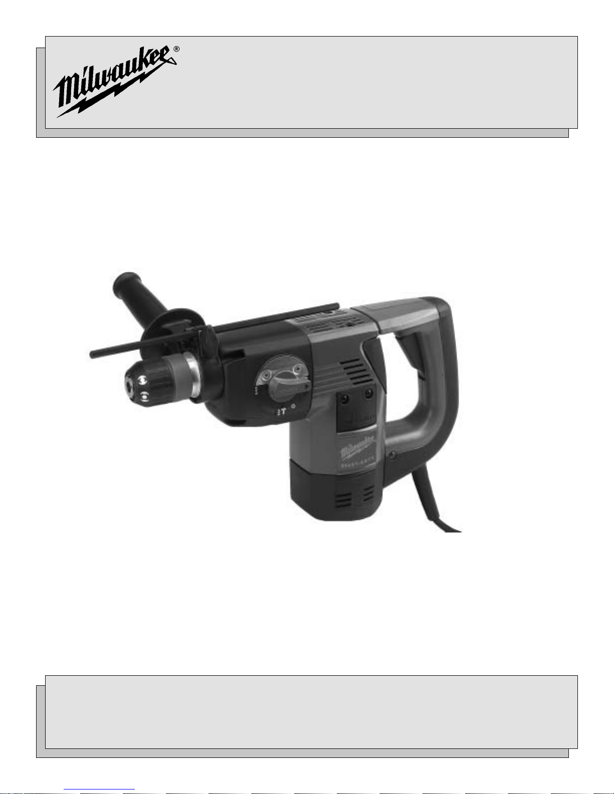
1
8
1. Side handle
2. Clamping screw
3. Depth gauge rod
4. Trigger
5. Mode selector lever
6. Quik-Change spindle for
removable bit holder (5360-21 only)
7. Removable SDS bit holder
8. Non-removable SDS bit holder
FUNCTIONAL DESCRIPTION
2
7
6
3
4
5
page 3
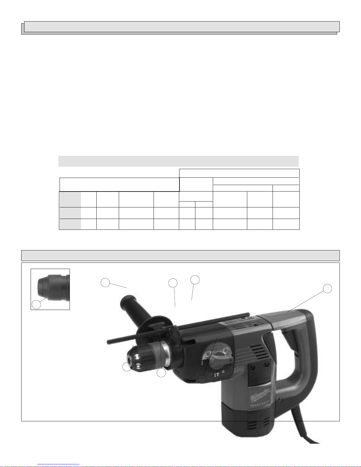
GROUNDING
EXTENSION CORDS
WARNING!
Improperly connecting the grounding wire can
result in the risk of electric shock. Check with a
qualified electrician if you are in doubt as to
whether the outlet is properly grounded. Do not
modify the plug provided with the tool. Never
remove the grounding prong from the plug. Do
not use the tool if the cord or plug is damaged. If
damaged, have it repaired by a MILWAUKEE
service facility before use. If the plug will not fit
the outlet, have a proper outlet installed by a
qualified electrician.
Grounded Tools:
Tools with Three Prong Plugs
Tools marked “Grounding Required”
have a three wire cord and three
prong grounding plug. The plug must
be connected to a properly grounded
outlet (See Figure A). If the tool should
electrically malfunction or break
down, grounding provides a low resistance path to carry electricity
away from the user, reducing the risk
of electric shock.
The grounding prong in the plug is connected through the green wire
inside the cord to the grounding system in the tool. The green wire in the
cord must be the only wire connected to the tool's grounding system and
must never be attached to an electrically “live” terminal.
Your tool must be plugged into an appropriate outlet, properly installed
and grounded in accordance with all codes and ordinances. The plug
and outlet should look like those in Figure A.
Double Insulated Tools:
Tools with Two Prong Plugs
Tools marked “Double Insulated” do
not require grounding. They have a
special double insulation system
which satisfies OSHA requirements
and complies with the applicable
standards of Underwriters Laboratories, Inc., the Canadian Standard
Association and the National Electrical Code. Double Insulated tools may
be used in either of the 120 volt outlets shown in Figures B and C.
Fig. A
Fig. B
Fig. C
Grounded tools require a three wire extension cord. Double insulated
tools can use either a two or three wire extension cord. As the distance
from the supply outlet increases, you must use a heavier gauge extension cord. Using extension cords with inadequately sized wire causes a
serious drop in voltage, resulting in loss of power and possible tool
damage. Refer to the table shown to determine the required minimum
wire size.
The smaller the gauge number of the wire, the greater the capacity of the
cord. For example, a 14 gauge cord can carry a higher current than a 16
gauge cord. When using more than one extension cord to make up the
total length, be sure each cord contains at least the minimum wire size
required. If you are using one extension cord for more than one tool, add
the nameplate amperes and use the sum to determine the required minimum wire size.
Guidelines for Using Extension Cords
• If you are using an extension cord outdoors, be sure it is marked
with the suffix “W-A” (“W” in Canada) to indicate that it is acceptable
for outdoor use.
• Be sure your extension cord is properly wired and in good electrical
condition. Always replace a damaged extension cord or have it
repaired by a qualified person before using it.
• Protect your extension cords from sharp objects, excessive heat
and damp or wet areas.
Recommended Minimum Wire Gauge
Nameplate
Amperes
8.1 - 12
12.1 - 15
15.1 - 20
* Based on limiting the line voltage drop to five
volts at 150% of the rated amperes.
for Extension Cords*
25'
0 - 5
5.1 - 8
16
16
14
12
10
Extension Cord Length
100'
14
12
10
10
150'
12
10
--
--
--
--
50'
16
16
14
12
10
75'
16
14
12
10
10
200'
12
--
--
--
--
READ AND SA VE ALL INSTRUCTIONS
FOR FUTURE USE.
Symbology
Double Insulated
page 4
BPM
Underwriters Laboratories, Inc.
Canadian Standards Association
Mexican Approvals Marking
Volts Alternating Current
No Load Revolutions per Minute
Amperes
Blows per Minute (BPM)
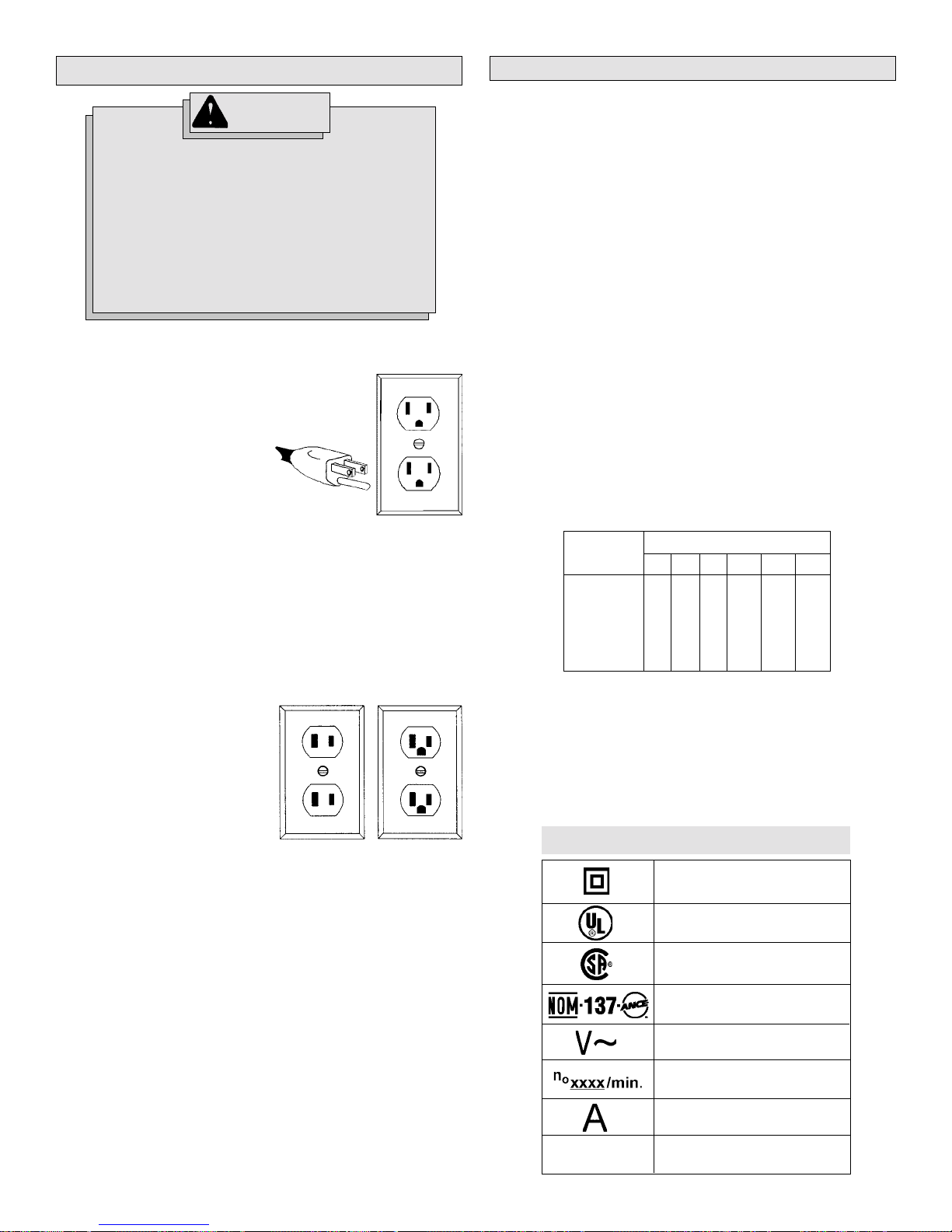
TOOL ASSEMBLY
WARNING!
To reduce the risk of injury, always unplug
tool before attaching or removing accessories. Use only specifically recommended
accessories. Others may be hazardous.
Removing the Bit Holder (Fig. 1)
Fig. 1
Bit holder
Spindle
For Cat. No. 5360-21 only:
1. Hold the bit holder firmly and pull back red sleeve toward tool.
2. Bit holder will pop out of the spindle, hold it firmly.
Inserting the Bit Holder
1. Push bit holder into spindle turning until locked into position.
2. Remember to clean and lightly grease the spindle from time to time.
Adjusting the Side Handle Position
1. Loosen the clamping screw slightly.
2. Pull the side handle forward and turn it to the required angle.
3. Fit the side handle into the nonslip mounting until it adjusts into place
and retighten the clamping screw.
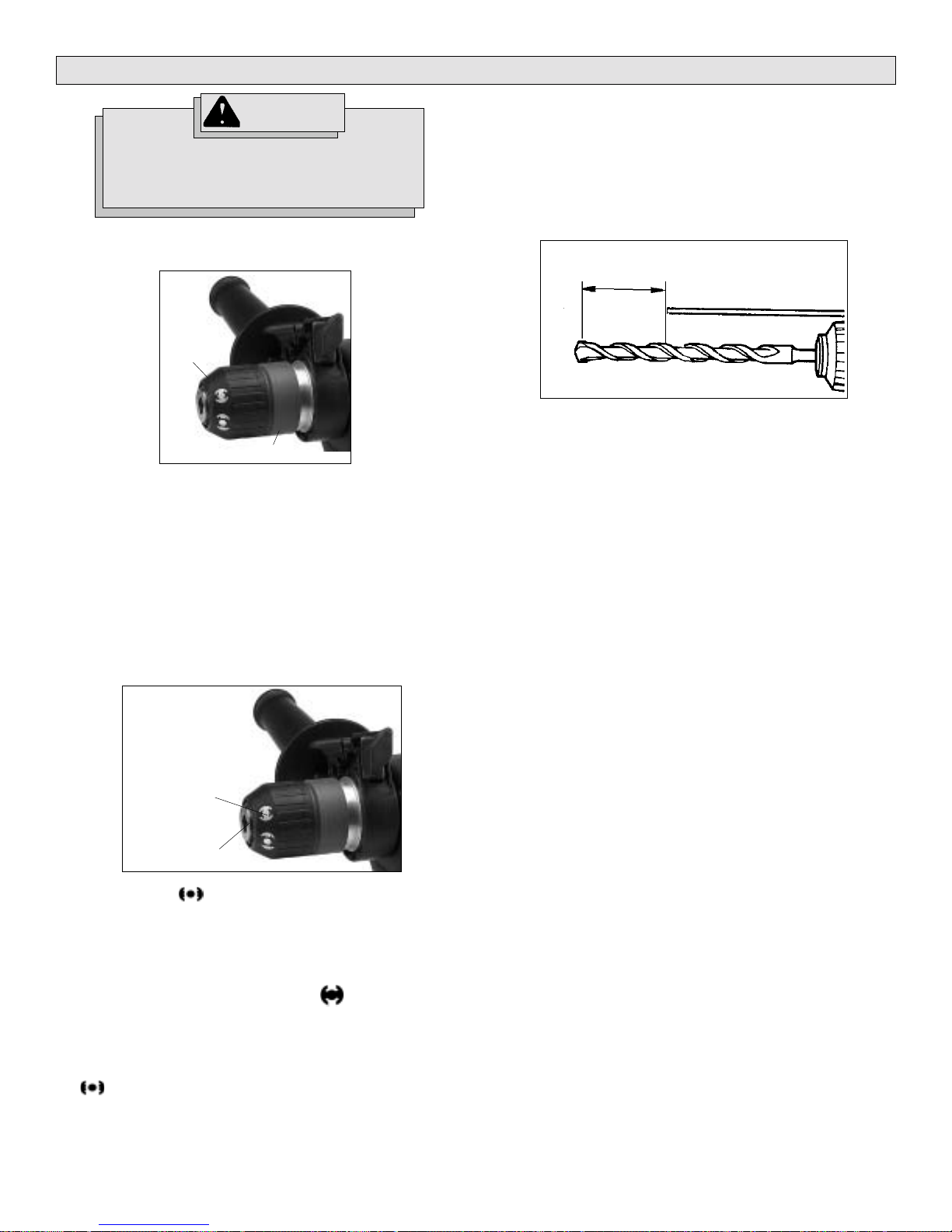
Setting the Depth Gauge (Fig. 3)
Fig. 3
Drilling Depth
1. Loosen the clamping screw.
2. Slide the depth gauge rod backward or forward until it is set for the
desired depth.
NOTE: The drilling depth is the distance between the tip of the bit and
the tip of the depth gauge rod.
3. Tighten the clamping screw securely.
Inserting Drill Bit or Chisel (Fig. 2)
NOTE: Only use accessories with SDS shanks.
Fig. 2
Symbols
Dimple
1. Align the symbol with dimple on front of bit holder.
2. Rotate bit until the oval groove on the bit aligns with the symbol on
the tool.
3. While pushing in the bit, turn it slightly, if necessary.
4. Push the bit in completely.
5. Turn the bit holder collar so that the symbol aligns with dimple on
front of the bit holder. The tool should now be locked.
6. Push and pull on the bit to check that it is locked properly — it should
move slightly.
7. To remove bits and chisels, turn bit holder collar so that the symbol
aligns with dimple on the front of bit holder. Remove bit.
page 5
OPERA TION
WARNING!
To reduce the risk of injury, always wear
eye protection.
Selecting Action (Fig. 4)
MILWAUKEE Rotary Hammers have three settings: drill only, rotary
hammer, and hammer only.
Fig. 4
1. For drilling, turn the selector lever so the arrow on the lever points to
the twist drill symbol .
2. For rotary hammering, turn the selector lever so the arrow points to
the hammer and twist drill symbol .
3. For hammering only, turn the selector lever so the arrow points to
the hammer symbol .
4. To freely rotate the bit to the desired angle for hammering only, turn
the selector lever so the arrow points to the symbol . Then, follow
step 3.
NOTE: To engage the hammering mechanism, maintain pressure on the
bit. When pressure on the bit is released, the hammering action will stop.
O
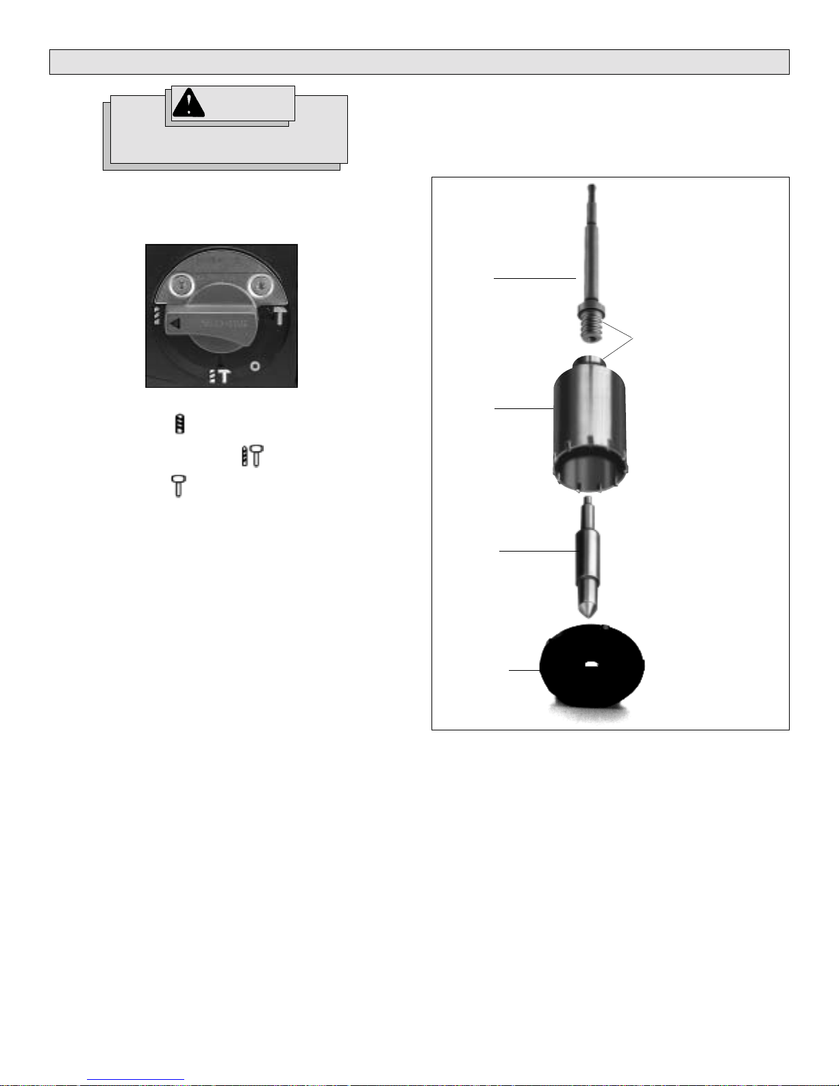
Using Core Bits (Fig. 5)
Core bits are useful for drilling large holes for conduit and pipe.
MILWAUKEE Heavy-Duty Thin Wall Core Bits have heat treated steel
bodies with durable carbide tips. They are specially designed for fast,
accurate drilling with combined hammering and rotary action.
Fig. 5
Adapter
Clean and lubricate
threads
Core Bit
Center Pin
Starting, Stopping & Controlling Speed
1. To start the tool, pull trigger.
2. To stop the tool, release trigger.
3. To vary the speed, increase or decrease pressure applied to trigger.
Operating
Position the tool, grasp the handles firmly and pull the trigger. Always
hold the tool securely using both handles to maintain control. This tool
has been designed to achieve top performance with only moderate
pressure. Let the tool do the work.
If the speed begins to drop off when drilling large or deep holes, pull the
bit partially out of the hole while the tool is running to help clear dust. Do
not use water to settle the dust since it will clog the bit flutes and tend to
make the bit bind in the hole. If the bit should bind, a built-in, nonadjustable slip clutch prevents the bit from turning. If this occurs, stop
the tool, free the bit and begin again.
Guide Plate
1. Clean and lubricate the threads on the adapter and core bit as
indicated (Fig. 5) to make later removal easier. Screw the threaded
end of the adapter into the rear of the core bit.
2. Push the guide plate onto the pointed end of the center pin. Insert the
center pin with guide plate assembly into to the core bit. Be sure the
small end of the center pin is securely placed into the hole in the
center of the adapter.
3. Insert the adapter into the bit holder of the tool as described in
“Inserting Drill Bit or Chisel”. Set the rotary hammer/drill lever to
rotary hammer.
4. Press the center pin firmly against your center mark, hold the tool
firmly and pull the trigger.
5. After drilling to about the depth of the core bit teeth, remove the
center pin and guide plate from the core bit. Resume drilling.
6. After you have finished drilling the hole, hold the tool upwards,
pointing it away from your body, and run it briefly in forward to
loosen the core bit from the adapter.
MILWAUKEE Heavy-Duty Thin Wall Core Bits drill holes up to 3" deep. To
make deeper holes, remove the bit, break and remove the core. Resume
drilling.
page 6
 Loading...