

Page 1
INSTRUCTION MANUAL
MANUEL D'INSTRUCTION
MANUAL DE INSTRUCCIONES
Trimmer
Affleureuse
Recortadora
3708
3708F
3708FC
002000
DOUBLE INSULATION
DOUBLE ISOLATION
DOBLE AISLAMIENTO
WARNING:
For your personal safety, READ and UNDERSTAND before using.
SAVE THESE INSTRUCTIONS FOR FUTURE REFERENCE.
AVERTISSEMENT:
Pour votre propre sécurité, prière de lire attentivement avant l’utilisation.
GARDER CES INSTRUCTIONS POUR RÉFÉRENCE ULTÉRIEURE.
ADVERTENCIA:
Para su seguridad personal, LEA DETENIDAMENTE este manual antes de usar la herramienta.
GUARDE ESTAS INSTRUCCIONES PARA FUTURA REFERENCIA.
Page 2

ENGLISH
SPECIFICATIONS
Model 3708 / 3708F 3708FC
Collet chuck capacity 1/4” 1/4”
No load speed (RPM) 35,000/min. 26,000/min.
Overall length 308 mm (12 - 1/8”) 308 mm (12 - 1/8”)
Net weight 1.3 kg (2.9 lbs) 1.3 kg (2.9 lbs)
• Due to our continuing programme of research and development, the specifications herein are subject to change
without notice.
• Note: Specifications may differ from country to country.
GENERAL SAFETY RULES
USA002-2
(For All Tools)
WARNING:
Read and understand all instructions.
Failure to follow all instructions listed below,
may result in electric shock, fire and/or serious personal injury.
SAVE THESE INSTRUCTIONS
Work Area
1. Keep your work area clean and well lit. Cluttered
benches and dark areas invite accidents.
2. Do not operate power tools in explosive atmo-
spheres, such as in the presence of flammable
liquids, gases, or dust. Power tools create sparks
which may ignite the dust or fumes.
3. Keep bystanders, children, and visitors away
while operating a power tool. Distractions can
cause you to lose control.
Electrical Safety
4. Double insulated tools are equipped with a
polarized plug (one blade is wider than the
other.) This plug will fit in a polarized outlet only
one way. If the plug does not fit fully in the outlet,
reverse the plug. If it still does not fit, contact a
qualified electrician to install a polarized outlet.
Do not change the plug in any way. Double insula-
tion eliminates the need for the three wire
grounded power cord and grounded power supply
system.
5. Avoid body contact with grounded surfaces
such as pipes, radiators, ranges and refrigerators. There is an increased risk of electric shock if
your body is grounded.
6. Do not expose power tools to rain or wet conditions. Water entering a power tool will increase the
risk of electric shock.
7. Do not abuse the cord. Never use the cord to
carry the tools or pull the plug from an outlet.
Keep cord away from heat, oil, sharp edges or
moving parts. Replace damaged cords immediately. Damaged cords increase the risk of electric
shock.
8. When operating a power tool outside, use an
outdoor extension cord marked “W-A” or “W”.
These cords are rated for outdoor use and reduce
the risk of electric shock.
Personal Safety
9. Stay alert, watch what you are doing and use
common sense when operating a power tool. Do
not use tool while tired or under the influence of
drugs, alcohol, or medication. A moment of inat-
tention while operating power tools may result in
serious personal injury.
10. Dress properly. Do not wear loose clothing or
jewelry. Contain long hair. Keep your hair, clothing, and gloves away from moving parts. Loose
clothes, jewelry, or long hair can be caught in moving parts.
11. Avoid accidental starting. Be sure switch is off
before plugging in. Carrying tools with your finger
on the switch or plugging in tools that have the
switch on invites accidents.
12. Remove adjusting keys or wrenches before turning the tool on. A wrench or a key that is left
attached to a rotating part of the tool may result in
personal injury.
13. Do not overreach. Keep proper footing and balance at all times. Proper footing and balance
enables better control of the tool in unexpected situations.
14. Use safety equipment. Always wear eye protection. Dust mask, non-skid safety shoes, hard hat, or
hearing protection must be used for appropriate conditions. Ordinary eye or sun glasses are NOT eye
protection.
2
Page 3

Tool Use and Care
15. Use clamps or other practical way to secure and
support the workpiece to a stable platform. Hold-
ing the work by hand or against your body is unstable and may lead to loss of control.
16. Do not force tool. Use the correct tool for your
application. The correct tool will do the job better
and safer at the rate for which it is designed.
17. Do not use tool if switch does not turn it on or
off. Any tool that cannot be controlled with the
switch is dangerous and must be repaired.
18. Disconnect the plug from the power source
before making any adjustments, changing
accessories, or storing the tool. Such preventive
safety measures reduce the risk of starting the tool
accidentally.
19. Store idle tools out of reach of children and
other untrained persons. Tools are dangerous in
the hands of untrained users.
20. Maintain tools with care. Keep cutting tools
sharp and clean. Properly maintained tools with
sharp cutting edges are less likely to bind and are
easier to control.
21. Check for misalignment or binding of moving
parts, breakage of parts, and any other condition
that may affect the tools operation. If damaged,
have the tool serviced before using. Many acci-
dents are caused by poorly maintained tools.
22. Use only accessories that are recommended by
the manufacturer for your model. Accessories
that may be suitable for one tool, may become hazardous when used on another tool.
SERVICE
23. Tool service must be performed only by qualified
repair personnel. Service or maintenance per-
formed by unqualified personnel could result in a risk
of injury.
24. When servicing a tool, use only identical
replacement parts. Follow instructions in the
Maintenance section of this manual. Use of unau-
thorized parts or failure to follow Maintenance
instructions may create a risk of electric shock or
injury.
USE PROPER EXTENSION CORD: Make sure your
extension cord is in good condition. When using an
extension cord, be sure to use one heavy enough to
carry the current your product will draw. An undersized
cord will cause a drop in line voltage resulting in loss of
power and overheating. Table 1 shows the correct size to
use depending on cord length and nameplate ampere
rating. If in doubt, use the next heavier gage. The smaller
the gage number, the heavier the cord.
Table 1: Minimum gage for cord
Ampere Rating
Volts Total length of cord in feet
120 V 25 ft. 50 ft. 100 ft. 150 ft.
More Than Not More Than AWG
0 6 18 16 16 14
18 16 14 12610
10 12 16 16 14 12
12 16 14 12
Not Recommended
SPECIFIC SAFETY RULES
USB052-2
DO NOT let comfort or familiarity with
product (gained from repeated use)
replace strict adherence to trimmer
safety rules. If you use this tool unsafely
or incorrectly, you can suffer serious personal injury.
1. Hold tool by insulated gripping surfaces when
performing an operation where the cutting tool
may contact hidden wiring or its own cord. Con-
tact with a “live” wire will make exposed metal parts
of the tool “live” and shock the operator.
2. Wear hearing protection during extended period
of operation.
3. Handle the bits very carefully.
4. Check the bit carefully for cracks or damage
before operation. Replace cracked or damaged
bit immediately.
5. Avoid cutting nails. Inspect for and remove all
nails from the workpiece before operation.
6. Hold the tool firmly.
7. Keep hands away from rotating parts.
8. Make sure the bit is not contacting the workpiece before the switch is turned on.
9. Before using the tool on an actual workpiece, let
it run for a while. Watch for vibration or wobbling
that could indicate improperly installed bit.
10. Be careful of the bit rotating direction and the
feed direction.
11. Do not leave the tool running. Operate the tool
only when hand-held.
3
Page 4
12. Always switch off and wait for the bit to come to
a complete stop before removing the tool from
workpiece.
13. Do not touch the bit immediately after operation;
it may be extremely hot and could burn your
skin.
14. Always lead the power supply cord away from
the tool towards the rear.
15. Do not smear the tool base carelessly with thinner, gasoline, oil or the like. They may cause
cracks in the tool base.
16. Draw attention to the need to use cutters of the
correct shank diameter and which are suitable
for the speed of the tool.
17. Some material contains chemicals which may be
toxic. Take caution to prevent dust inhalation
and skin contact. Follow material supplier safety
data.
SAVE THESE INSTRUCTIONS
WARNING:
MISUSE or failure to follow the safety
rules stated in this instruction manual
may cause serious personal injury.
SYMBOLS
USD201-2
The followings show the symbols used for tool.
V............................volts
A ...........................amperes
Hz..........................hertz
....................alternating current
.......................no load speed
.......................Class II Construction
.../min....................revolutions or reciprocation per
minute
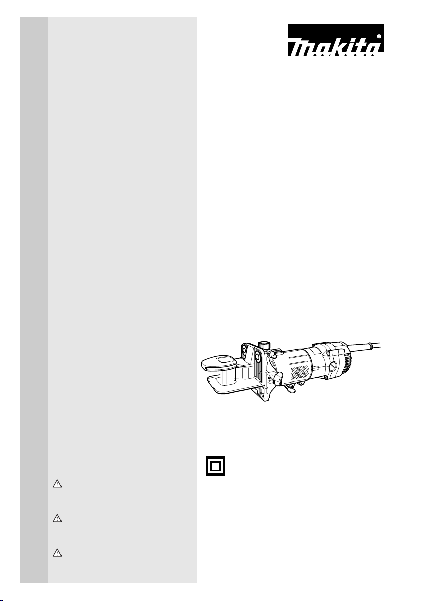
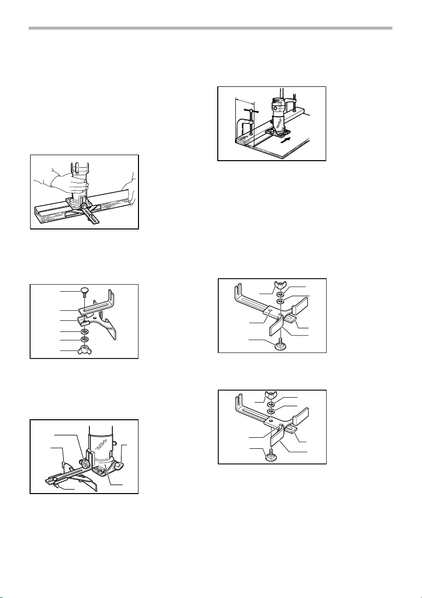
Adjusting bit protrusion
1
2
To adjust the bit protrusion, loosen the lever and move
the tool base up or down as desired by turning the adjusting roller. After adjusting, tighten the lever firmly to
secure the tool base.
Adjusting angle of tool base
1
2
3
Loosen the wing bolts and adjust the angle of the tool
base (5° per graduation) to obtain the desired cutting
angle.
002001
1. Lever
2. Scale
3
4
5
4
3. Bit protrusion
4. Adjusting roller
002002
1. Wing bolt
2. Graduation
3. Trimmer shoe
4. Amount of
5. Base
chamfering
Adjusting amount of chamfering
To adjust the amount of chamfering, loosen the wing nuts
and adjust the trimmer shoe.
CAUTION:
• With the tool unplugged and switch in the “OFF”
position, rotate the collet nut on the tool several
times to be sure that the bit turns freely and does
not contact the base or trimmer shoe in any way.
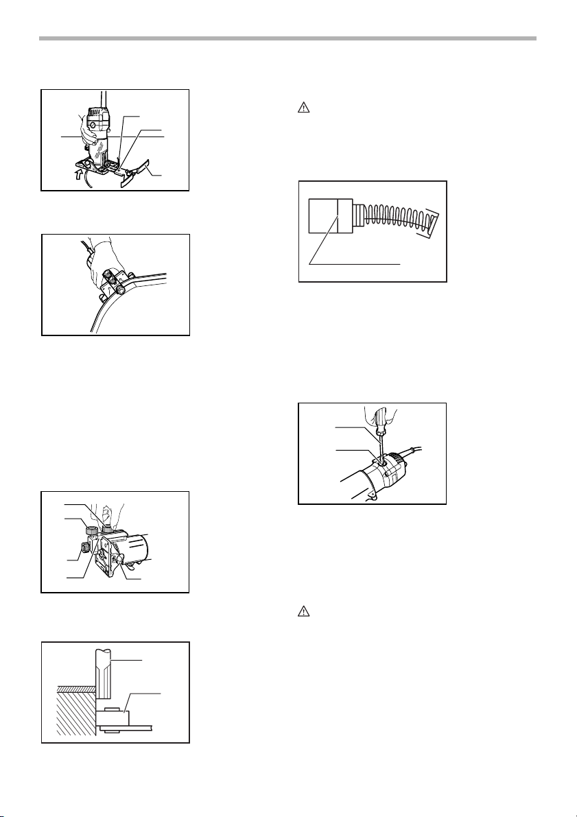
Switch action
001982
1. Switch lever
FUNCTIONAL DESCRIPTION
CAUTION:
• Always be sure that the tool is switched off and
unplugged before adjusting or checking function on
the tool.
1
4
Page 5
CAUTION:
• Before plugging in the tool, always be sure that the
tool is switched off.
• Switch can be locked in “ON” position for ease of
operator comfort during extended use. Apply caution when locking tool in “ON” position and maintain
firm grasp on tool.
To start the tool, move the switch lever to the I (ON) position. To stop the tool, move the switch lever to the O
(OFF) position.
Electronic function
For model 3708FC only
The tool equipped with electronic function are easy to
operate because of the following features.
Constant speed control
Electronic speed control for obtaining constant speed.
Possible to get fine finish, because the rotating speed is
kept constant even under load condition.
Soft start
Soft-start feature minimizes start-up shock, and makes
the tool start smoothly.
Lighting up the lamps
For model 3708F/3708FC only
CAUTION:
• Do not look in the light or see the source of light
directly.
To turn on the lamp, start the tool. Then, the lamp lights
up the top of the bit. To turn it off, stop the tool.
NOTE:
• Use a dry cloth to wipe the dirt off the lens of lamp.
Be careful not to scratch the lens of lamp, or it may
lower the illumination.
CAUTION:
• Do not tighten the collet nut without inserting a bit,
or the collet cone will break.
• Use only the wrenches provided with the tool.
Insert the bit all the way into the collet cone and tighten
the collet nut securely with the two wrenches.
To remove the bit, follow the installation procedure in
reverse.
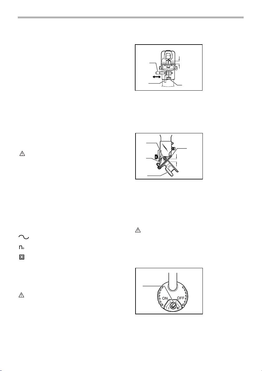
Installing trimmer shoe
(after it has been removed from the tool)
3
4
1
2
1. Bolt 2. Flat washer (large)
3. Trimmer shoe 4. Flat washer (small)
5. Spring washer 6. Wing nut
7. Base
NOTE:
• The trimmer shoe is factory installed on the tool.
Use the bolts, wing nuts, spring washers and flat washers to install the trimmer shoe as shown in the figure.
002004
5
6
7
OPERATION
002005
1
1. Trimmer shoe
2. Base
ASSEMBLY
CAUTION:
• Always be sure that the tool is switched off and
unplugged before carrying out any work on the tool.
Installing or removing trimmer bit
2
1
3
002003
1. Loosen
2. Tighten
3. Hold
2
Turn the tool on without the bit making any contact with
the workpiece and wait until the bit attains full speed.
Then move the tool over the workpiece surface, keeping
the tool base and trimmer shoe flush with the sides of the
workpiece.
NOTE:
• This tool can be used as a conventional trimmer
when you remove the trimmer shoe.
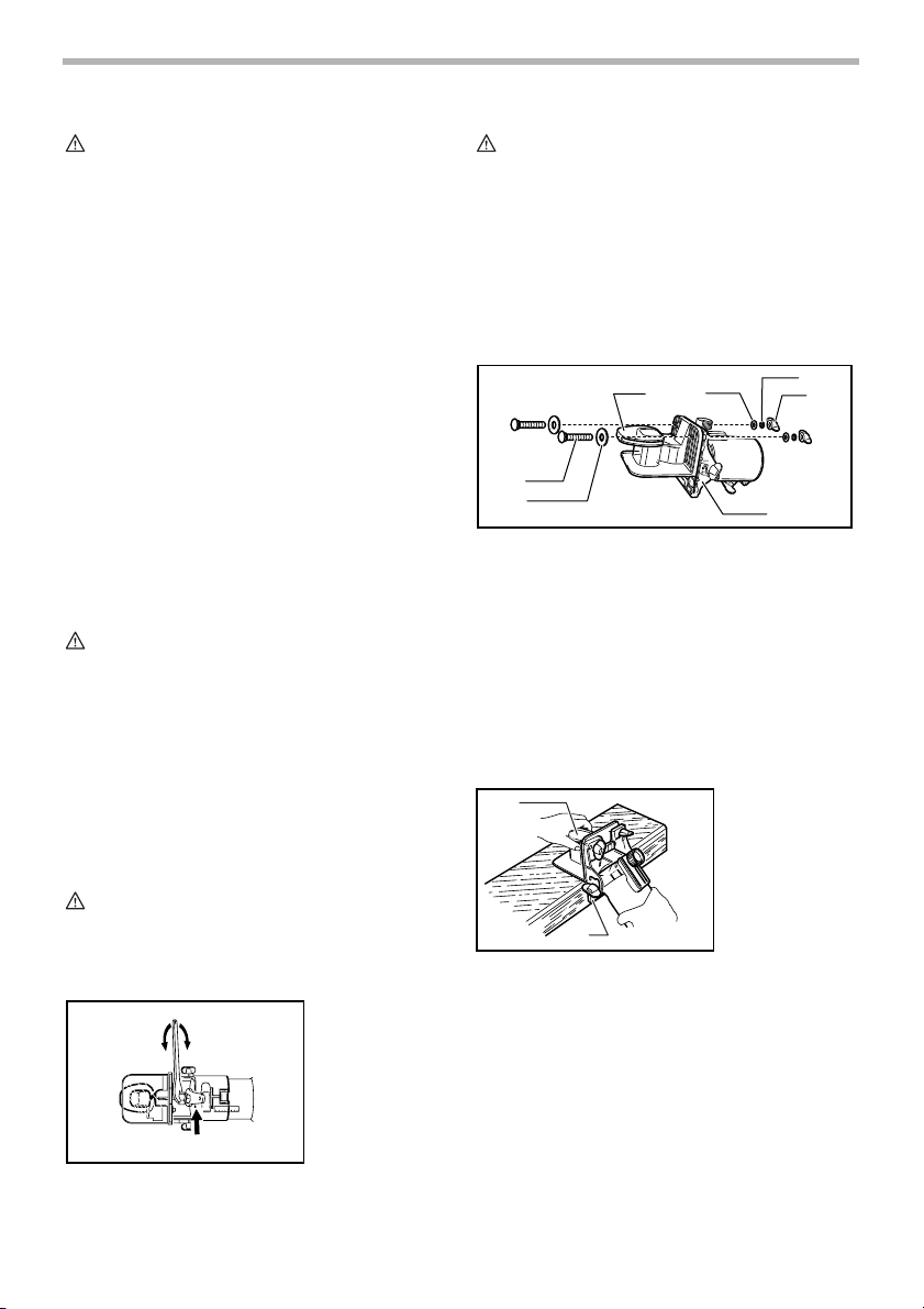
When doing edge cutting, the workpiece surface should
be on the left side of the bit in the feed direction.
5
Page 6
001984
2
1
2
4
4
3
1. Workpiece 2. Bit revolving direction
3. View from the top of the
4. Feed direction
tool
CAUTION:
• Since excessive cutting may cause overload of the
motor or difficulty in controlling the tool, the depth of
cut should not be more than 3 mm (1/8”) at a pass
when cutting grooves. When you wish to cut
grooves more than 3 mm (1/8”) deep, make several
passes with progressively deeper bit settings.
NOTE:
• Moving the tool forward too fast may cause a poor
quality of cut, or damage to the bit or motor. Moving
the tool forward too slowly may burn and mar the
cut. The proper feed rate will depend on the bit size,
the kind of workpiece and depth of cut. Before
beginning the cut on the actual workpiece, it is
advisable to make a sample cut on a piece of scrap
lumber. This will show exactly how the cut will look
as well as enable you to check dimensions.
• When using the trimmer shoe, the straight guide or
the trimmer guide, be sure to keep it on the right
side in the feed direction. This will help to keep it
flush with the side of the workpiece.
2
001985
1. Feed direction
3
2. Bit revolving
direction
3. Workpiece
1
4. Straight guide
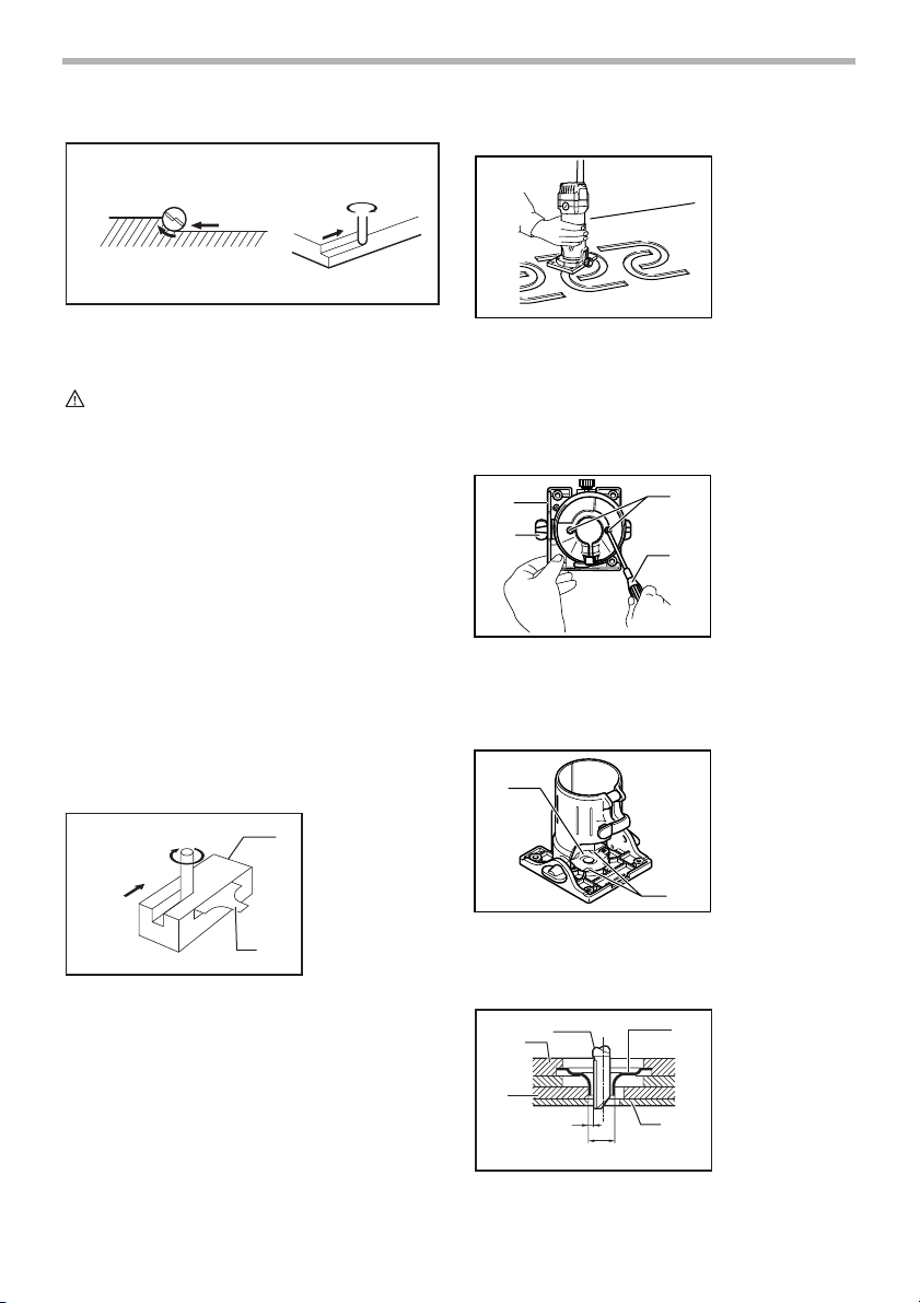
Templet guide
001986
The templet guide provides a sleeve through which the
bit passes, allowing use of the trimmer with templet patterns.
Remove the tool base from the tool. Loosen the wing
bolts and secure the tool base horizontally. Loosen the
two screws on the tool base.
1
2
Place the templet guide on the tool base. There are four
convex portions on the templet guide. Secure two of the
002006
3
4
1. Base
2. Wing bolt
3. Screws
4. Screwdriver
four convex portions using the two screws. Install the tool
base on the tool.
002007
1. Templet guide
1
2. Convex portions
2
4
Secure the templet to the workpiece. Place the tool on
the templet and move the tool with the templet guide sliding along the side of the templet.
1
2
3
4
10mm(3/8”)
001988
6
5
1. Straight bit
2. Base
3. Templet
4. Distance (X)
5. Workpiece
6. Templet guide
10
6
Page 7
NOTE:
• The workpiece will be cut a slightly different size
from the templet. Allow for the distance (X) between
the router bit and the outside of the templet guide.
The distance (X) can be calculated by using the following equation:
Distance (X) = (outside diameter of the templet guide router bit diameter) / 2
Straight guide (Accessory)
The straight guide is effectively used for straight cuts
when chamfering or grooving.
Attach the guide plate to the straight guide with the bolt,
the wave washer, the flat washer and the wing nut.
1
2
3
4
5
001989
001990
1. Bolt
2. Guide plate
3. Straight guide
4. Flat washer
5. Wave washer
6. Wing nut
6
straight board to the workpiece and use it as a guide
against the trimmer base. Feed the tool in the direction of
the arrow.
002009
A
Circular work
Circular work may be accomplished if you assemble the
straight guide and guide plate as shown in the figures.
Min. and max. radius of circles to be cut (distance
between the center of circle and the center of bit) are as
follows:
Min.: 70 mm (2-3/4”)
Max.: 221 mm (8-11/16”)
For cutting circles between 70 mm (2-3/4”) and 121 mm
(4-3/4”) in radius.
1
6
7
001993
2
3
4
5
1. Wing nut
2. Wave washer
3. Flat washer
4. Guide plate
5. Straight guide
6. Center hole
7. Bolt
Loosen the wing bolts and secure the tool base horizontally. Attach the straight guide with the clamp screw (A).
Loosen the wing nut on the straight guide and adjust the
distance between the bit and the straight guide. At the
desired distance, tighten the wing nut securely.
1
2
002008
3
1. Clamp screw
(A)
2. Straight guide
3. Wing bolt
4. Base
5. Wing nut
5
When cutting, move the tool with the straight guide flush
with the side of the workpiece.
If the distance (A) between the side of the workpiece and
the cutting position is too wide for the straight guide, or if
4
the side of the workpiece is not straight, the straight
guide cannot be used. In this case, firmly clamp a
For cutting circles between 121 mm (4-3/4”) and 221 mm
(8-11/16”) in radius.
1
001994
2
3
1. Wing nut
2. Wave washer
3. Flat washer
4. Guide plate
6
7
4
5
5. Straight guide
6. Center hole
7. Bolt
NOTE:
• Circles between 172 mm (6-3/4”) and 186 mm (7-5/
16”) in radius cannot be cut using this guide.
Align the center hole in the straight guide with the center
of the circle to be cut. Drive a nail less than 6 mm (1/4”)
in diameter into the center hole to secure the straight
guide. Pivot the tool around the nail in clockwise direction.
7
Page 8
002010
1. Nail
2
2. Center hole
3. Straight guide
1
3
MAINTENANCE
CAUTION:
• Always be sure that the tool is switched off and
unplugged before attempting to perform inspection
or maintenance.
Replacing carbon brushes
001145
1. Limit mark
Trimmer guide
Trimming, curved cuts in veneers for furniture and the like
can be done easily with the trimmer guide. The guide
roller rides the curve and assures a fine cut.
Loosen the wing bolts and secure the tool base horizontally.
Install the trimmer guide on the tool base with the clamp
screw (A). Loosen the clamp screw (B) and adjust the
distance between the bit and the trimmer guide by turning the adjusting screw (1 mm (3/64”) per turn). At the
desired distance, tighten the clamp screw (B) to secure
the trimmer guide in place.
1
2
3
4
When cutting, move the tool with the guide roller riding
the side of the workpiece.
002011
002012
1. Clamp screw
(A)
2. Adjusting screw
3. Clamp screw
(B)
4. Trimmer guide
5
2
5. Wing bolt
001998
1. Workpiece
2. Bit
3. Guide roller
3
1
1
Remove and check the carbon brushes regularly.
Replace when they wear down to the limit mark. Keep
the carbon brushes clean and free to slip in the holders.
Both carbon brushes should be replaced at the same
time. Use only identical carbon brushes.
Use a screwdriver to remove the brush holder caps. Take
out the worn carbon brushes, insert the new ones and
secure the brush holder caps.
1
001999
1. Screwdriver
2. Brush holder
cap
2
To maintain product SAFETY and RELIABILITY, repairs,
any other maintenance or adjustment should be performed by Makita Authorized or Factory Service Centers,
always using Makita replacement parts.
ACCESSORIES
CAUTION:
• These accessories or attachments are recom-
mended for use with your Makita tool specified in
this manual. The use of any other accessories or
attachments might present a risk of injury to persons. Only use accessory or attachment for its
stated purpose.
If you need any assistance for more details regarding
these accessories, ask your local Makita Service Center.
• Straight & groove forming bits
• Edge forming bits
• Laminate trimming bits
8
Page 9

• Straight guide assembly
• Trimmer guide assembly
• Trimmer base assembly (For chamfering with
straight bit)
• Trimmer shoe
• Templet guide
• Collet cone 1/4”
• Wrench 10
• Wrench 17
EN0006-1
MAKITA LIMITED ONE YEAR WARRANTY
Warranty Policy
Every Makita tool is thoroughly inspected and tested
before leaving the factory. It is warranted to be free of
defects from workmanship and materials for the period of
ONE YEAR from the date of original purchase. Should
any trouble develop during this one year period, return
the COMPLETE tool, freight prepaid, to one of Makita’s
Factory or Authorized Service Centers. If inspection
shows the trouble is caused by defective workmanship or
material, Makita will repair (or at our option, replace)
without charge.
This Warranty does not apply where:
• repairs have been made or attempted by others:
• repairs are required because of normal wear and
tear:
• the tool has been abused, misused or improperly
maintained:
• alterations have been made to the tool.
IN NO EVENT SHALL MAKITA BE LIABLE FOR ANY
INDIRECT, INCIDENTAL OR CONSEQUENTIAL DAMAGES FROM THE SALE OR USE OF THE PRODUCT.
THIS DISCLAIMER APPLIES BOTH DURING AND
AFTER THE TERM OF THIS WARRANTY.
MAKITA DISCLAIMS LIABILITY FOR ANY IMPLIED
WARRANTIES, INCLUDING IMPLIED WARRANTIES
OF “MERCHANTABILITY” AND “FITNESS FOR A SPECIFIC PURPOSE,” AFTER THE ONE YEAR TERM OF
THIS WARRANTY.
This Warranty gives you specific legal rights, and you
may also have other rights which vary from state to state.
Some states do not allow the exclusion or limitation of
incidental or consequential damages, so the above limitation or exclusion may not apply to you. Some states do
not allow limitation on how long an implied warranty lasts,
so the above limitation may not apply to you.
9
Page 10

FRANÇAIS
SPÉCIFICATIONS
Modèle 3708 / 3708F 3708FC
Capacité du mandrin à bague 1/4” 1/4”
Vitesse à vide (T/MIN) 35,000/min. 26,000/min.
Longueur totale 308 mm (12 - 1/8”) 308 mm (12 - 1/8”)
Poids net 1.3 kg (2.9 lbs) 1.3 kg (2.9 lbs)
• Le fabricant se réserve le droit de modifier sans avertissement les spécifications.
• Note: Les spécifications peuvent varier selon les pays.
RÈGLES DE SÉCURITÉ
GÉNÉRALES
USA002-2
(Pour tous les outils)
AVERTISSEMENT:
Vous devez lire et comprendre toutes les
instructions. Le non-respect, même partiel,
des instructions ci-après entraîne un risque
de choc électrique, d’incendie et/ou de
blessures graves.
CONSERVEZ CES
INSTRUCTIONS
Aire de travail
1. Veillez à ce que l’aire de travail soit propre et
bien éclairée. Le désordre et le manque de lumière
favorisent les accidents.
2. N’utilisez pas d’outils électriques dans une
atmosphère explosive, par exemple en présence
de liquides, de gaz ou de poussières
inflammables. Les outils électriques créent des
étincelles qui pourraient enflammer les poussières
ou les vapeurs.
3. Tenez à distance les curieux, les enfants et les
visiteurs pendant que vous travaillez avec un
outil électrique. lls pourraient vous distraire et vous
faire une fausse manoeuvre.
Sécurité électrique
4. Les outils à double isolation sont équipés d’une
fiche polarisée (une des lames est plus large que
l’autre), qui ne peut se brancher que d'une seule
façon dans une prise polarisée. Si la fiche
n’entre pas parfaitement dans la prise, inversez
sa position ; si elle n’entre toujours pas bien,
demandez à un électricien qualifié d’installer une
prise de courant polarisée. Ne modifiez pas la
fiche de l’outil. La double isolation élimine le
besoin d’un cordon d’alimentation à trois fils avec
mise à la terre ainsi que d’une prise de courant mise
à la terre.
5. Évitez tout contact corporel avec des surfaces
mises à la terre (tuyauterie, radiateurs,
cuisinières, réfrigérateurs, etc.). Le risque de
choc électrique est plus grand si votre corps est en
contact avec la terre.
6. N’exposez pas les outils électriques à la pluie ou
à l’eau. La présence d’eau dans un outil électrique
augmente le risque de choc électrique.
7. Ne maltraitez pas le cordon. Ne transportez pas
l’outil par son cordon et ne débranchez pas la
fiche en tirant sur le cordon. N’exposez pas le
cordon à la chaleur, à des huiles, à des arêtes
vives ou à des pièces en mouvement.
Remplacez immédiatement un cordon
endommagé. Un cordon endommagé augmente le
risque de choc électrique.
8. Lorsque vous utilisez un outil électrique à
l’extérieur, employez un prolongateur pour
l’extérieur marqué “W-A” ou “W”. Ces cordons
sont faits pour être utilisés à l’extérieur et réduisent
le risque de choc électrique.
Sécurité des personnes
9. Restez alerte, concentrez-vous sur votre travail
et faites preuve de jugement. N’utilisez pas un
outil électrique si vous êtes fatigué ou sous
l'influence de drogues, d’alcool ou de
médicaments. Un instant d’inattention suffit pour
entraîner des blessures graves.
10. Habillez-vous convenablement. Ne portez ni
vêtements flottants ni bijoux. Confinez les
cheveux longs. N’approchez jamais les
cheveux, les vêtements ou les gants des pièces
en mouvement. Des vêtements flottants, des bijoux
ou des cheveux longs risquent d’être happés par
des pièces en mouvement.
11. Méfiez-vous d’un démarrage accidentel. Avant
de brancher l’outil, assurez-vous que son
interrupteur est sur ARRÊT. Le fait de transporter
10
Page 11

un outil avec le doigt sur la détente ou de brancher
un outil dont l’interrupteur est en position MARCHE
peut mener tout droit à un accident.
12. Enlevez les clés de réglage ou de serrage avant
de démarrer l’outil. Une clé laissée dans une pièce
tournante de l’outil peut provoquer des blessures.
13. Ne vous penchez pas trop en avant. Maintenez
un bon appui et restez en équilibre en tout
temps. Un bonne stabilité vous permet de mieux
réagir à une situation inattendue.
14. Utilisez des accessoires de sécurité. Portez
toujours des lunettes ou une visière. Selon les
conditions, portez aussi un masque antipoussière,
des bottes de sécurité antidérapantes, un casque
protecteur et/ou un appareil antibruit. Les lunettes
ordinaires et les lunettes de soleil NE constituent
PAS des lunettes de protection.
Utilisation et entretien des outils
15. Immobilisez le matériau sur une surface stable
au moyen de brides ou de toute autre façon
adéquate. Le fait de tenir la pièce avec la main ou
contre votre corps offre une stabilité insuffisante et
peut amener un dérapage de l’outil.
16. Ne forcez pas l’outil. Utilisez l’outil approprié à
la tâche. L’outil correct fonctionne mieux et de façon
plus sécuritaire. Respectez aussi la vitesse de
travail qui lui est propre.
17. N’utilisez pas un outil si son interrupteur est
bloqué. Un outil que vous ne pouvez pas
commander par son interrupteur est dangereux et
doit être réparé.
18. Débranchez la fiche de l’outil avant d’effectuer
un réglage, de changer d’accessoire ou de
ranger l’outil. De telles mesures préventives de
sécurité réduisent le risque de démarrage accidentel
de l’outil.
19. Rangez les outils hors de la portée des enfants
et d’autres personnes inexpérimentées. Les
outils sont dangereux dans les mains d’utilisateurs
novices.
20. Prenez soin de bien entretenir les outils. Les
21. Soyez attentif à tout désalignement ou
22. N’utilisez que des accessoires que le fabricant
RÉPARATI ON
23. La réparation des outils électriques doit être
24. Pour la réparation d’un outil, n’employez que
UTLISEZ UN CORDON PROLONGATEUR ADÉQUAT:
Assurez-vous que le cordon prolongateur est en bon
état. Lors de l’utilisation d’un cordon prolongateur,
utilisez sans faute un cordon assez gros pour conduire le
courant que le produit nécessite. Un cordon trop petit
provoquera une baisse de tension de secteur, résultant
en une perte de puissance et une surchauffe. Le Tableau
1 indique la dimension appropriée de cordon selon sa
longueur et selon l’intensité nominale indiquée sur la
plaque signalétique. En cas de doute sur un cordon
donné, utilisez le cordon suivant (plus gros). Plus le
numéro de gabarit indiqué est petit, plus le cordon est
gros.
Tableau 1. Gabarit minimum du cordon
Intensit
é nominale
Volts Longueur totale du cordon en pieds
120 V 25 pi 50 pi 100 pi 150 pi
Plus de Pas plus de Calibre am
0 6 18 16 16 14
10 12 16 16 14 12
12 16 14 12
outils de coupe doivent être toujours bien
affûtés et propres. Des outils bien entretenus, dont
les arêtes sont bien tranchantes, sont moins
susceptibles de coincer et plus faciles à diriger.
coincement des pièces en mouvement, à tout
bris ou à toute autre condition préjudiciable au
bon fonctionnement de l’outil. Si vous constatez
qu’un outil est endommagé, faites-le réparer
avant de vous en servir. De nombreux accidents
sont causés par des outils en mauvais état.
recommande pour votre modèle d’outil. Certains
accessoires peuvent convenir à un outil, mais être
dangereux avec un autre.
confiée à un réparateur qualifié. L’entretien ou la
réparation d’un outil électrique par un amateur peut
avoir des conséquences graves.
des pièces de rechange d’origine. Suivez les
directives données à la section «ENTRETIEN» de
ce manuel. L’emploi de pièces non autorisées ou le
non-respect des instructions d’entretien peut créer
un risque de choc électrique ou de blessures.
éricain des fils
18 16 14 12610
Non recommandé
11
Page 12

RÈGLES DE SÉCURITÉ
PARTICULI ÈRES
USB052-2
NE vous laissez PAS tromper (au fil d’une
utilisation répétée) par un sentiment
d’aisance et de familiarité avec l’outil, en
négligeant le respect rigoureux des
règles de sécurité qui accompagnent
l’affleureuse. L’utilisation non sécuritaire
ou incorrecte de cet outil comporte un
risque de blessure grave.
1. Tenez l’outil par ses surfaces de prise isolées
pendant toute opération où l’outil de coupe
pourrait venir en contact avec un câblage
dissimulé ou avec son propre cordon. En cas de
contact avec un conducteur sous tension, les pièces
métalliques à découvert de l’outil transmettraient un
choc électrique à l’utilisateur.
2. Portez une protection d’oreille lors des travaux
de longue durée.
3. Maniez les fraises avec soin.
4. Vérifiez bien l’absence de fissures ou de
dommages sur la fraise avant l’utilisation.
Remplacez immédiatement toute fraise fissurée
ou endommagée.
5. Évitez les clous. Avant de travailler votre pièce,
inspectez-la et retirez-en tous les clous.
6. Tenez l’outil fermement.
7. Gardez les mains éloignées des pièces en
rotation.
8. Assurez-vous que la lame ne touche pas la pièce
à travailler avant que le contact ne soit mis.
9. Avant de commencer à travailler, laissez tourner
l’outil à vide un instant ; assurez-vous qu’il n’y a
ni vibration ni ballottement, ce qui indiquerait
une fraise mal fixée.
10. Vérifiez toujours le sens de rotation de la fraise
et le sens de déplacement de l’outil.
11. N’abandonnez pas l’outil alors qu’il tourne. Ne
faites fonctionner l’outil qu’une fois que vous
l’avez bien en main.
12. Avant de retirer l’outil de la pièce, coupez
toujours le contact et attendez que la fraise soit
complètement arrêtée.
13. Ne touchez pas la fraise immédiatement après
son arrêt ; elle peut être extrêmement chaude et
pourrait vous brûler.
14. Faites toujours courir le cordon d’alimentation à
l’écart de l’outil, vers l’arrière.
15. Veillez à maintenir la base de l’outil à l’écart des
produits tels que du diluant, de l’essence ou de
l’huile. Ils peuvent causer des fissures sur la
base de l’outil.
16. Attirez l’attention sur la nécessité d’utiliser des
couteaux ayant le diamètre de queue adéquat et
adaptées à la vitesse de l’outil.
17. Certains matériaux contiennent des produits
chimiques qui peuvent être toxiques. Prenez les
précautions nécessaires pour éviter l’inhalation
de ces poussières ou leur contact avec la peau.
Conformez-vous aux consignes de sécurité du
fournisseur du matériau.
CONSERVEZ CE MODE
D’EMPLOI
AVERTISSEMENT:
Une MAUVAISE UTILISATION de l’outil ou
l’ignorance des consignes de sécurité du
présent manuel d’instructions peuvent
entraîner une grave blessure.
SYMBOLES
Les symboles utilisés pour l’outil sont présentés cidessous.
V ...........................volts
A...........................ampères
Hz .........................hertz
...................courant alternatif
.......................vitesse à vide
.......................construction, catégorie II
.../min ...................tours ou alternances par minute
USD201-2
DESCRIPTION DU
FONCTIONNEMENT
ATTENTION:
• Assurez-vous toujours que l’outil est hors tension et
débranché avant de l’ajuster ou de vérifier son
fonctionnement.
12
Page 13

Ajustage de la fraise
1
2
Pour régler la saillie de la fraise, desserrez le levier et
déplacez l’embase de l’outil, vers le haut ou vers le bas,
de la hauteur voulue en tournant la roulette de réglage.
Votre ajustage terminé, serrez le levier à fond pour
assurer en place l’embase.
Réglage de l’angle de l’embase
1
2
3
Desserrez les boulons à oreilles et ajustez l’angle de
l’embase (5° par graduation) de façon à obtenir l’angle
de taille voulu.
002001
1. Levier
2. Échelle
3
4
5
4
3. Partie saillante
4. Rouleau de
002002
1. Boulon à
2. Graduation
3. Sabot de
4. Grandeur de
5. Base
de la fraise
réglage
oreilles
dressage
chanfrein
Largeur de chanfrein
Pour régler la largeur de chanfrein, desserrez les écrous
à oreilles et ajustez le support d’affleurage horizontal.
ATTENTION:
• Une fois l’outil débranché et l’interrupteur placé sur
la position “OFF”, faites tourner plusieurs fois
l’écrou de mandrin sur l’outil de façon à vous
assurer que la fraise tourne librement et n’entre pas
en contact avec l’embase ou le support d’affleurage
horizontal.
Interrupteur
1
001982
1. Levier
d’interrupteur
ATTENTION:
• Toujours vérifier que l’outil soit mis sur l’arrêt avant
de le brancher.
• Pour rendre le travail de l’utilisateur plus confortable
lors d’une utilisation prolongée, l’interrupteur peut
être verrouillé en position de marche. Soyez
prudent lorsque vous verrouillez l’outil en position
de marche, et maintenez une poigne solide sur
l’outil.
Pour démarrer l’outil, poussez le levier d’interrupteur du
côté I (ON). Pour l’arrêter, poussez le du côte O (OFF).
Fonction électronique
Pour le modèle 3708FC uniquement
Les outils dotés de fonctions électroniques sont faciles à
utiliser grâce aux caractéristiques suivantes.
Commande de vitesse constante
Commande électronique de la vitesse afin d’obtenir une
vitesse constante. Permet d’obtenir une finition précise
puisque la vitesse de rotation est maintenue constante
même dans des conditions de lourde charge.
Démarrage en douceur
La fonction de démarrage en douceur minimise le choc
initial et permet à l’outil de démarrer en douceur.
Allumage de la lampe
Pour les modèles 3708F/3708FC uniquement
ATTENTION:
• Evitez de regarder directement le faisceau
lumineux ou sa source.
Pour allumer la lampe, faites démarrer l’outil. La lampe
éclaire alors la partie supérieure de la fraise. Pour
éteindre la lampe, arrêtez l’outil.
NOTE:
• Utilisez un chiffon sec pour essuyer la saleté qui
recouvre la lentille de la lampe. Prenez garde de
rayer la lentille de la lampe, pour éviter une
diminution de l’éclairage.
ASSEMBLAGE
ATTENTION:
• Avant d’effectuer toute intervention sur l’outil,
assurez-vous toujours qu’il est hors tension et
débranché.
13
Page 14

Pose et dépose de la fraise d’affleurage
2
1
002003
1. Desserrer
2. Serrer
3. Prise
UTILISATION
1
002005
1. Sabot de
dressage
2. Base
3
ATTENTION:
• Ne serrez pas l’écrou de mandrin sans y avoir
inséré une fraise, sinon vous risquez de briser le
cône de mandrin.
• N’utilisez que les clés fournies avec l’outil.
Insérez la fraise à fond dans le cône du mandrin et
serrez bien l’écrou de mandrin à l’aide des deux clés.
Pour retirer la fraise, suivez la procédure d’installation en
sens inverse.
Pose du support d’affleurage horizontal
(quand il a été retiré de d’outil)
3
4
1
2
1. Boulon 2. Rondelle plate (grande)
3. Sabot de dressage 4. Rondelle plate (petite)
5. Rondelle élastique 6. Écrou à oreilles
7. Base
NOTE:
• Le support d’affleurage horizontal est livré installé
sur l’outil.
A l’aide des boulons, écrous à oreilles, rondelles
élastiques et plates, installez le support d’affleurage
horizontal de la façon indiquée par la figure.
002004
5
6
7
2
Mettez le contact sans que la fraise soit au contact de la
pièce à travailler et attendez qu’elle ait atteint sa pleine
vitesse. Déplacez alors votre outil sur la surface de la
pièce, en maintenant l’embase et le support d’affleurage
horizontal parfaitement en contact avec les côtés de la
pièce à travailler.
NOTE:
• Cet outil peut s’utiliser à la façon d’une affleureuse
ordinaire si vous retirez le support d’affleurage
horizontal.
Quand vous faites une coupe sur rebord, la surface de la
pièce doit être du côté gauche de la fraise dans le sens
de progression de l’outil.
1
2
1. Pièce 2. Sens de rotation du foret
3. Vu à partir du haut de
l’outil
ATTENTION:
• Une taille trop profonde risque de forcer le moteur
ou de rendre difficile le contrôle de l’outil ; quand
vous rainez, limitez donc votre profondeur de taille
à 3 mm (1/8”) par passage. Pour des rainures d’une
profondeur supérieure, opérez en plusieurs
passages et en approfondissant progressivement.
NOTE:
• Si vous déplacez votre outil trop vite vers l’avant,
vous risquez d’obtenir une coupe de qualité
médiocre et d’endommager la fraise ou le moteur.
Si vous allez trop lentement, vous risquez de brûler
la pièce et de gâcher la coupe. La vitesse de
progression adéquate dépend du calibre de la
fraise, de la nature de la pièce et de la profondeur
de coupe. Avant de commencer votre coupe sur la
4
3
4
4. Sens d’alimentation
001984
2
14
Page 15

pièce, nous vous conseillons de faire un essai sur
un morceau de chute de bois. Cela vous montrera
exactement l’allure qu’aura votre coupe et vous
permettra de vérifier les dimensions.
• Lorsque vous vous servez du support d’affleurage
horizontal, du guide de coupe rectiligne ou du guide
d’affleurage, veillez à bien l’installer du côté droit de
l’outil dans le sens de la progression. Vous pourrez
ainsi le maintenir parfaitement en contact avec les
côtés de la pièce que vous taillez.
2
001985
3
1. Sens
d’alimentation
2. Sens de rotation
du foret
1
Guide de gabarit
3. Pièce
4. Guide de coupe
4
001986
rectiligne
Le guide de gabarit est une courte section de tube
traversée par la fraise, ce qui permet d’utiliser
l’affleureuse avec des gabarits de modèles.
Retirez l’embase de l’outil. Desserrez les boulons à
oreilles et posez l’embase bien horizontalement.
Relâchez les deux vis de l’embase.
1
2
002006
3
4
1. Base
2. Boulon à
oreilles
3. Vis
4. Tournevis
002007
1. Guide de
1
gabarit
2. Parties
convexes
2
Fixez le gabarit sur la pièce. Placez l’outil sur le gabarit et
déplacez-le en faisant glisser le guide de gabarit le long
du côté du gabarit.
1
2
001988
1. Foret à denture
6
2. Base
droite
3. Gabarit
3
4
10mm(3/8”)
5
4. Distance (X)
5. Pièce
6. Guide de
gabarit 10
NOTE:
• La pièce à travailler sera taillée selon une
dimension légèrement différente de celle du
gabarit. Prévoyez donc un distance (X) entre la
fraise et l’extérieur du guide de gabarit. Cette
distance (X) se calcule selon l’équation :
Distance (X) = diamètre extérieur du guide de gabarit diamètre de la fraise/2
Guide de coupe rectiligne (accessoire)
001989
Placez le guide de gabarit sur l’embase. Il y a quatre
sections convexes sur le guide. Assurez-en deux sur les
quatre en vous servant des deux vis. Installez de
nouveau l’embase sur l’outil.
Le guide de coupe rectiligne est efficace pour obtenir des
coupes droites quand vous chanfreinez ou rainez.
Fixer la plaque de guide sur le guide de coupe rectiligne
avec le boulon, la rondelle vague, la rondelle plate et
l’écrou à oreilles.
15
Page 16

001990
1
2
3
4
5
6
1. Boulon
2. Plaque de
guidage
3. Guide de coupe
rectiligne
4. Rondelle plate
5. Rondelle
ondulée
6. Écrou à oreilles
Desserrez les boulons à oreilles et posez l’embase bien
horizontalement. Fixez le guide de coupe rectiligne sur
l’outil à l’aide de la vis de serrage (A). Desserrez l’écrou
à oreilles du guide et réglez la distance entre celui-ci et la
fraise. Une fois obtenue la distance désirée, serrez à
fond l’écrou à oreilles.
002008
1. Vis de serrage
1
2
(A)
2. Guide de coupe
3
rectiligne
3. Boulon à
oreilles
4. Base
5. Écrou à oreilles
5
Quand vous coupez, déplacez l’outil en maintenant le
guide en appui avec le côté de la pièce à travailler.
Si la distance (A) entre le côté de la pièce à travailler et le
tracé est trop grande pour le guide de coupe rectiligne,
4
ou si ce même côté n’est pas rectiligne, vous ne pouvez
pas utiliser ce guide. En ce cas, fixez solidement, à l’aide
de serre-joints, une pièce de bois rectiligne à la pièce à
travailler et servez-vous en comme de guide au contact
de l’embase de l’affleureuse. Déplacez celle-ci dans la
direction de la flèche.
002009
A
Tailles circulaires
Des tailles circulaires peuvent être réalisées si vous
assemblez le guide de coupe rectiligne et la plaque du
guide comme sur la figure.
Les rayons min. et max. des tailles circulaires réalisables
(les distances entre le centre du cercle et le centre de la
fraise) sont les suivants :
Min. : 70 mm (2-3/4”)
Max. : 221 mm (8-11/16”)
Pour la taille de cercles de 70 mm (2-3/4”) à 121 mm (4-
3/4”) de rayon.
1
001993
2
3
1. Écrou à oreilles
2. Rondelle
ondulée
3. Rondelle plate
6
7
4. Plaque de
4
5. Guide de coupe
5
6. Trou de
guidage
rectiligne
centrage
7. Boulon
Pour la taille de cercles de 121 mm (4-3/4”) à 221 mm (811/16”) de rayon.
1
001994
2
3
1. Écrou à oreilles
2. Rondelle
ondulée
3. Rondelle plate
6
7
4. Plaque de
4
5. Guide de coupe
5
guidage
rectiligne
6. Trou de
centrage
7. Boulon
NOTE:
• Les cercles de rayons compris entre 172 mm (6-3/
4”) et 186 mm (7-5/16”) ne peuvent pas être taillés
avec ce guide.
Alignez le trou de centrage du guide de coupe rectiligne
sur le centre du cercle à tailler. Enfoncez un clou de
diamètre inférieur à 6 mm (1/4”) dans le trou de centrage
pour assurer le guide en place. Faites pivoter l’outil
autour du clou en le tournant dans le sens des aiguilles
d’une montre.
002010
1. Clou
1
2. Trou de
2
3. Guide de coupe
centrage
rectiligne
3
16
Page 17

Guide d’affleurage
002011
Remplacement des charbons
001145
1
1. Trait de limite
d’usure
Le guide d’affleurage permet d’effectuer aisément
affleurage ou tailles courbes des bois de placage pour
mobilier, etc. Le galet du guide suit la courbure et assure
une coupe parfaite.
Desserrez les boulons et fixez l’embase horizontalement.
Installez le guide d’affleurage sur l’embase de l’outil avec
la vis de serrage (A). Desserrez la vis de serrage (B) et
ajustez la distance entre le fraise et le guide d’affleurage
en tournant la vis de réglage (1 mm (3/64”) par tour). À la
distance désirée, serrez la vis de serrage (B) pour fixer le
guide d’affleurage en position.
1
2
3
4
Quand vous coupez, déplacez l’outil avec le galet du
guide courant sur le côté de la pièce à travailler.
1
002012
1. Vis de serrage
(A)
2. Vis de réglage
3. Vis de serrage
(B)
4. Guide
5
2
3
d’affleurage
5. Boulon à
oreilles
001998
1. Pièce
2. Embout
3. Rouleau-guide
ENTRETIEN
ATTENTION:
• Assurez-vous toujours que l’outil est hors tension et
débranché avant d’y effectuer tout travail
d’inspection ou d’entretien.
Retirez et vérifiez régulièrement les charbons.
Remplacez-les lorsqu’ils sont usés jusqu’au trait de limite
d’usure. Maintenez les charbons propres et en état de
glisser aisément dans les porte-charbon. Les deux
charbons doivent être remplacés en même temps.
N’utilisez que des charbons identiques.
Utilisez un tournevis pour retirer les bouchons de portecharbon. Enlevez les charbons usés, insérez-en de
nouveaux et revissez solidement les bouchons de portecharbon.
1
2
Pour maintenir la SÉCURITÉ et la FIABILITÉ du produit,
les réparations, tout autre travail d’entretien ou de
réglage doivent être effectués dans un centre de service
Makita agréé ou un centre de service de l’usine Makita,
exclusivement avec des pièces de rechange Makita.
001999
1. Tournevis
2. Bouchon de
porte-charbon
ACCESSOIRES
ATTENTION:
• Ces accessoires ou pièces complémentaires sont
recommandés pour l’utilisation avec l’outil Makita
spécifié dans ce mode d’emploi. L’utilisation de tout
autre accessoire ou pièce complémentaire peut
comporter un risque de blessure. N’utilisez les
accessoires ou pièces qu’aux fins auxquelles ils ont
été conçus.
Si vous désirez obtenir plus de détails concernant ces
accessoires, veuillez contacter le centre de service
après-vente Makita le plus près.
• Fraises pour coupes rectilignes et rainures
• Fraises pour rebord
• Fraises pour affleurage de stratifié
• Ensemble de guide de coupe rectiligne
• Ensemble de guide d’affleurage
17
Page 18

• Ensemble d’embase d’affleurage (Pour chanfrein
avec la fraise pour coupe rectiligne)
• Support d’affleurage horizontal
• Guide de gabarit
• Cône du mandrin 1/4”
• Clé 10
• Clé17
EN0006-1
GARANTIE LIMITÉE D’UN AN MAKITA
Politique de garantie
Chaque outil Makita est inspecté rigoureusement et testé
avant sa sortie d’usine. Nous garantissons qu’il sera
exempt de défaut de fabrication et de vice de matériau
pour une période d’UN AN à partir de la date de son
achat initial. Si un problème quelconque devait survenir
au cours de cette période d’un an, veuillez retourner
l’outil COMPLET, port payé, à une usine ou à un centre
de service après-vente Makita. Makita réparera l’outil
gratuitement (ou le remplacera, à sa discrétion) si un
défaut de fabrication ou un vice de matériau est
découvert lors de l’inspection.
Cette garantie ne s’applique pas dans les cas où:
• des réparations ont été effectuées ou tentées par
un tiers:
• des réparations s’imposent suite à une usure
normale:
• l’outil a été malmené, mal utilisé ou mal entretenu:
• l’outil a subi des modifications.
MAKITA DÉCLINE TOUTE RESPONSABILITÉ POUR
TOUT DOMMAGE ACCESSOIRE OU INDIRECT LIÉ À
LA VENTE OU À L’UTILISATION DU PRODUIT. CET
AVIS DE NON-RESPONSABILITÉ S’APPLIQUE À LA
FOIS PENDANT ET APRÈS LA PÉRIODE COUVERTE
PAR CETTE GARANTIE.
MAKITA DÉCLINE TOUTE RESPONSABILITÉ QUANT
À TOUTE GARANTIE TACITE, INCLUANT LES
GARANTIES TACITES DE “QUALITÉ MARCHANDE” ET
“ADÉQUATION À UN USAGE PARTICULIER” APRÈS
LA PÉRIODE D’UN AN COUVERTE PAR CETTE
GARANTIE.
Cette garantie vous donne des droits spécifiques
reconnus par la loi, et possiblement d’autres droits, qui
varient d’un État à l’autre. Certains États ne permettant
pas l’exclusion ou la limitation des dommages
accessoires ou indirects, il se peut que la limitation ou
exclusion ci-dessus ne s’applique pas à vous. Certains
États ne permettant pas la limitation de la durée
d’application d’une garantie tacite, il se peut que la
limitation ci-dessus ne s’applique pas à vous.
18
Page 19

ESPAÑOL
ESPECIFICACIONES
Modelo 3708 / 3708F 3708FC
Especificaciones eléctricas en México
Capacidad del ajustador del mandril 1/4” 1/4”
Revoluciones por minuto (r.p.m.) 35 000/min. 26 000/min.
Longitud total 308 mm (12 - 1/8”) 308 mm (12 - 1/8”)
Peso neto 1,3 kg (2,9 lbs) 1,3 kg (2,9 lbs)
• Debido a un programa continuo de investigación y desarrollo, las especificaciones aquí dadas están sujetas a
cambios sin previo aviso.
• Nota: Las especificaciones pueden ser diferentes de país a país.
120 V 3,8 A 50/60 Hz 120 V 4,4 A 50/60 Hz
NORMAS DE SEGURIDAD
GENERALES
USA002-2
(Para todas las herramientas)
AVISO:
Lea y entienda todas las instrucciones.
El no seguir todas las instrucciones listadas
abajo, podrá resultar en una descarga
eléctrica, incendio y/o heridas personales
graves.
GUARDE ESTAS
INSTRUCCIONES
Área de trabajo
1. Mantenga su área de trabajo limpia y bien
iluminada. Los bancos de trabajo atestados y las
áreas oscuras son una invitación a accidentes.
2. No utilice las herramientas eléctricas en
atmósferas explosivas, tal como en la presencia
de líquidos, gases, o polvo inflamables. Las
herramientas eléctricas crean chispas que pueden
prender fuego al polvo o los humos.
3. Mantenga a los curiosos, niños, y visitantes
alejados mientras utiliza una herramienta
eléctrica. Las distracciones le pueden hacer perder
el control.
Seguridad eléctrica
4. Las herramientas doblemente aisladas están
equipadas con una clavija polarizada (uno de los
bornes es más ancho que el otro.) Esta clavija
encajará en una toma de corriente polarizada en
un sentido solamente. Si la clavija no encaja
totalmente en la toma de corriente, invierta la
clavija. Si aún así no encaja, póngase en
contacto con un electricista cualificado para que
le instale una toma de corriente polarizada. No
cambie la clavija de ninguna forma. El doble
aislamiento elimina la necesidad de disponer de
un cable de alimentación de tres hilos conectado a
tierra y de un sistema de suministro de corriente
conectado a tierra.
5. Evite tocar con el cuerpo superficies conectadas
a tierra tales como tubos, radiadores, cocinas y
refrigeradores. Si su cuerpo está puesto a tierra
existirá un mayor riesgo de que se produzca una
descarga eléctrica.
6. No exponga las herramientas eléctricas a la
lluvia ni a condiciones húmedas. La entrada de
agua en una herramienta eléctrica aumentará el
riesgo de que se produzca una descarga eléctrica.
7. No maltrate el cable. No utilice nunca el cable
para transportar las herramientas ni tire de él
para desenchufar la clavija de la toma de
corriente. Mantenga el cable alejado del calor,
aceite, bordes cortantes o partes en
movimiento. Reemplace los cables dañados
inmediatamente. Los cables dañados aumentarán
el riesgo de que se produzca una descarga
eléctrica.
8. Cuando emplee una herramienta eléctrica en
exteriores, utilice cables de extensión que lleven
la marca “W-A” o “W”. Estos cables están
catalogados para uso en exteriores y reducen el
riesgo de que se produzcan descargas eléctricas.
Seguridad personal
9. Esté alerta, concéntrese en lo que esté haciendo
y emplee el sentido común cuando utilice una
herramienta eléctrica. No utilice la herramienta
cuando esté cansado o bajo la influencia de
drogas, alcohol, o medicamentos. Un momento
sin atención mientras se están utilizando
herramientas eléctricas podrá resultar en heridas
personales graves.
19
Page 20

10. Vístase apropiadamente. No se ponga ropa
holgada ni joyas. Recójase el pelo si lo tiene
largo. Mantenga su pelo, ropa, y guantes
alejados de las partes en movimiento. La ropa
holgada, las joyas, o el pelo largo pueden
engancharse en las partes en movimiento.
11. Evite los arranques indeseados. Asegúrese de
que el interruptor esté apagado antes de
enchufar la herramienta. El transportar
herramientas con el dedo en el interruptor o el
enchufar herramientas que tengan el interruptor
puesto en encendido invita a accidentes.
12. Retire las llaves de ajuste y llaves de apriete
antes de encender la herramienta. Una llave de
ajuste o llave de apriete que sea dejada puesta en
una parte giratoria de la herramienta podrá resultar
en heridas personales.
13. No utilice la herramienta donde no alcance.
Mantenga los pies sobre suelo firme y el
equilibrio en todo momento. El mantener los pies
sobre suelo firme y el equilibrio permiten un mejor
control de la herramienta en situaciones
inesperadas.
14. Utilice equipo de seguridad. Póngase siempre
protección para los ojos. Las mascaras contra el
polvo, botas antideslizantes, casco rígido, o
protección para los oídos deberán ser utilizados
para las condiciones apropiadas. Las gafas
normales o de sol NO sirven para proteger los ojos.
Utilización y cuidado de las herramientas
15. Utilice mordazas u otros medios de sujeción
prácticos para sujetar y apoyar la pieza de
trabajo en una plataforma estable. El sujetar la
pieza de trabajo con la mano o contra su cuerpo es
inestable y puede llevar a la pérdida del control.
16. No force la herramienta. Utilice la herramienta
adecuada para su tarea. La herramienta correcta
realizará la tarea mejor y de forma más segura a la
potencia para la que ha sido diseñada.
17. No utilice la herramienta si el interruptor no la
enciende o la apaga. Cualquier herramienta que no
pueda ser controlada con el interruptor será
peligrosa y deberá ser reparada.
18. Desconecte la clavija de la toma de corriente
antes de hacer ajustes, cambiar accesorios, o
guardar la herramienta. Tales medidas de
seguridad preventiva reducirán el riesgo de que la
herramienta pueda ser puesta en marcha por
descuido.
19. Guarde las herramientas que no esté utilizando
fuera del alcance de los niños y otras personas
no preparadas. Las herramientas son peligrosas en
manos de personas no preparadas.
20. Dé mantenimiento a sus herramientas.
Mantenga las herramientas de corte afiladas y
limpias. Las herramientas con buen mentenimiento
y los bordes de corte afilados son menos
propensas a atorarse y más fáciles de controlar.
21. Compruebe que no haya partes móviles
desalineadas o atoradas, rotura de partes y
cualquier otra condición que pueda afectar al
funcionamiento de la herramienta. Si la
herramienta está dañada, haga que se la reparen
antes de utilizarla. Muchos accidentes son
ocasionados por herramientas con un mal
mantenimiento.
22. Utilice solamente accesorios que estén
recomendados por el fabricante para su modelo.
Los accesorios que puedan ser apropiados para
una herramienta, podrán resultar peligrosos cuando
se utilicen con otra herramienta.
SERVICIO
23. El servicio de la herramienta deberá ser
realizado solamente por personal de reparación
cualificado. Un servicio o mantenimiento realizado
por personal no cualificado podrá resultar en un
riesgo de sufrir heridas.
24. Cuando haga el servicio a una herramienta,
utilice solamente piezas de repuesto originales.
Siga las instrucciones de la sección de
Mantenimiento de este manual. La utilización de
piezas no autorizadas o el no seguir las
instrucciones de mantenimiento podrá crear un
riesgo de descargas eléctricas o heridas.
UTILICE CABLES DE EXTENSIÓN APROPIADOS:
Asegúrese de que su cable de extensión esté en buenas
condiciones. Cuando utilice un cable de extensión,
asegúrese de utilizar uno del calibre suficiente para
conducir la corriente que demande el producto. Un cable
de calibre inferior ocasionará una caída en la tensión de
línea y a su vez en una pérdida de potencia y
sobrecalentamiento. La Tabla 1 muestra el tamaño
correcto a utilizar dependiendo de la longitud del cable y
el amperaje nominal indicado en la placa de
características. Si no está seguro, utilice el siguiente
calibre más alto. Cuanto menor sea el número de calibre,
más corriente podrá conducir el cable.
20
Page 21

Tabla 1. Calibre mínimo para el cable
Amperaje nominal
Voltios Longitud total del cable en metros
120 V~
7,62 metoros 15,24 metoros 30,48 metoros 45,72 metoros
Más de No más de Calibre del cable (AWG)
0 6 18 16 16 14
18 16 14 12610
10 12 16 16 14 12
12 16 14 12
No se recomienda
NORMAS ESPECÍFICAS DE
SEGURIDAD
USB052-2
NO deje que la comodidad o familiaridad
con el producto (a base de utilizarlo
repetidamente) sustituya la estricta
observancia de las normas de seguridad
para la rebordeadora. Si utiliza esta
herramienta de forma no segura o
incorrecta, podrá sufrir graves heridas
personales.
1. Cuando realice una operación en la que la
herramienta de corte pueda entrar en contacto
con cableado oculto o con su propio cable,
sujete la herramienta por las superficies de
asimiento aisladas. El contacto con un cable con
corriente hará que la corriente circule por las partes
metálicas expuestas de la herramienta y podrá
electrocutar al operador.
2. Póngase protección para los oídos durante los
periodos de operación prolongados.
3. Maneje las brocas con mucho cuidado.
4. Inspeccione la broca cuidadosamente para ver
si tiene grietas o daños antes de comenzar la
operación. Reemplace la broca inmediatamente
si está agrietada o dañada.
5. Evite cortar clavos. Inspeccione y quite todos
los clavos de la pieza de trabajo antes de la
operación.
6. Sostenga la herramienta con firmeza.
7. Mantenga las manos alejadas de las piezas
giratorias.
8. Asegúrese de que la broca no esté haciendo
contacto con la pieza de trabajo antes de activar
el interruptor.
9. Antes de utilizar la herramienta en una pieza de
trabajo definitiva, déjela funcionar durante un
rato. Observe para ver si hay vibración o
bamboleo que pueda indicar una incorrecta
instalación de la broca.
10. Tenga cuidado con la dirección de giro y de
avance de la broca.
11. No deje la herramienta en marcha. Tenga en
marcha la herramienta solamente cuando la
tenga en la mano.
12. Apague siempre la herramienta y espere hasta
que la broca se haya parado completamente
antes de retirar la herramienta de la pieza de
trabajo.
13. No toque la broca inmediatamente después de la
operación; estará muy caliente y podrá y
quemarle la piel.
14. Tienda siempre el cable de alimentación alejado
de la herramienta hacia atrás.
15. No manche la base de la herramienta con
diluyente, gasolina, aceite o por el estilo. Estos
productos pueden ocasionar grietas en la base
de la herramienta.
16. Preste atención a la necesidad de utilizar fresas
de diámetro de vástago correcto y apropiado
para la velocidad de la herramienta.
17. Algunos materiales contienen sustancias
químicas que pueden ser tóxicas. Tome
precauciones para evitar la inhalación de polvo
o que éste tome contacto con la piel. Consulte la
información de seguridad del proveedor de los
materiales.
GUARDE ESTAS
INSTRUCCIONES
AVISO:
El mal uso o incumplimiento de las
reglas de seguridad descriptas en el
presente manual de instrucciones puede
ocasionar graves lesiones personales.
21
Page 22

SÍMBOLOS
A continuación se muestran los símbolos utilizados para
la herramienta.
V............................voltios
A ...........................amperios
Hz..........................hercios
....................corriente alterna
.......................velocidad en vacío
.......................Construcción clase II
.../min....................revoluciones, alternaciones o
carreras por minuto
USD201-2
DESCRIPCIÓN DEL
FUNCIONAMIENTO
PRECAUCIÓN:
• Asegúrese siempre de que la herramienta esté
apagada y desenchufada antes de ajustar o
comprobar cualquier función en la herramienta.
Ajuste de la saliente de la fresa
1
2
Para ajustar la protuberancia de la broca, afloje la
palanca y mueva la base de la herramienta hacia arriba o
hacia abajo conforme se desee al girar y ajustar el
rodillo. Después de ajustar, apriete la palanca
firmemente para fijar la base de la herramienta.
Ajuste del ángulo de la base de la herramienta
1
2
3
002001
1. Palanca
2. Escala
3
4
5
4
3. Saliente de la
4. Rodillo de
002002
1. Perno de
2. Graduación
3. Pie guía de
4. Grado de
5. Base
broca
ajuste
orejetas
corte
biselado
Afloje los pernos de orejetas y ajuste el ángulo de la
base de la herramienta (5° por graduación) para obtener
el ángulo de corte deseado.
Ajuste del grado de biselado
Para ajustar el grado de biselado, afloje las tuercas de
orejetas y ajuste la zapata de recorte.
PRECAUCIÓN:
• Con la herramienta desenchufada y el interruptor
puesto en la posición “OFF”, gire la tuerca de
apriete de la herramienta varias veces para
asegurarse de que la fresa gira libremente y que no
toca la base ni la zapata de recorte en ningún sitio.
Accionamiento del interruptor
1
PRECAUCIÓN:
• Antes de enchufar la herramienta, asegúrese
siempre de que está apagada.
• El interruptor puede ser bloqueado en la posición
“ON” (encendido) para mayor comodidad del
operario durante una utilización prolongada. Tenga
precaución cuando bloquee la herramienta en la
posición “ON” (encendido) y sujete la herramienta
firmemente.
Para poner en marcha la herramienta, mueva la palanca
del interruptor a la posición I (ON-encendido). Para parar
la herramienta, mueva la palanca del interruptor a la
posición O (OFF-apagado).
001982
1. Palanca del
interruptor
Función electrónica
Solamente para el modelo 3708FC.
La herramienta está equipada con funciones
electrónicas sencillas de operar debido a las siguientes
funcionalidades.
Control de velocidad constante
Control electrónico de velocidad para obtener una
velocidad constante. Es posible obtener un buen
acabado, dado que la velocidad de giro se mantiene
constante aún en condiciones de carga.
Encendido suave
La funcionalidad de encendido suave minimiza el
impacto de encendido y hace que la herramienta se
inicie suavemente.
22
Page 23

Encendido de las linternas
Solamente para el modelo 3708F/3708FC.
PRECAUCIÓN:
• No mire a la luz ni vea la fuente de luz
directamente.
Para encender la lámpara, arranque la herramienta.
Después, la lámpara alumbra la parte superior de la
broca. Para apagarla, pare la herramienta.
NOTA:
• Utilice un paño seco para quitar la suciedad de la
lente de la linterna. Tenga cuidado de no rayar la
lente de la linterna, porque podrá disminuir la
iluminación.
MONTAJE
PRECAUCIÓN:
• Asegúrese siempre de que la herramienta esté
apagada y desenchufada antes de realizar
cualquier trabajo en la herramienta.
Instalación o desmontaje de fresa de recorte
2
1
3
002003
1. Aflojar
2. Apretar
3. Sujetar
Instalación de la zapata de recorte (después
de haberla desmontado de la herramienta)
3
4
1
2
1. Perno 2. Arandela plana (grande)
3. Pie guía de corte 4. Arandela plana
5. Arandela de resorte 6. Tuerca de mariposa
7. Base
NOTA:
• La zapata de recorte sale de fábrica instalada en la
herramienta.
Instale la zapata de recorte utilizando los pernos, tuercas
de orejetas, arandelas de resorte y arandelas planas
como se muestra en la figura.
(pequeña)
002004
5
6
7
OPERACIÓN
002005
1
1. Pie guía de
corte
2. Base
PRECAUCIÓN:
• No apriete la tuerca de ajuste sin insertar una fresa
porque se romperá la tuerca de apriete.
• Utilice únicamente las llaves provistas con la
herramienta.
Inserte la broca por completo en el cono de sujeción y
apriete la tuerca firmemente con las dos llaves.
Para retirar la broca, siga el proceso inverso al de
instalación.
2
Encienda la herramienta sin que la fresa esté tocando la
pieza de trabajo y espere hasta que la fresa adquiera
plena velocidad. Después mueva la herramienta sobre la
superficie de la pieza de trabajo, manteniendo la base de
la herramienta y la zapata de recorte a ras con los
costados de la pieza de trabajo.
NOTA:
• Esta herramienta puede utilizarse como
rebordeadota normal quitando la zapata de recorte.
Cuando haga corte de bordes, la superficie de la pieza
de trabajo deberá estar en el costado izquierdo de la
fresa en la dirección de avance.
23
Page 24

001984
Guía de plantilla
001986
2
1
2
4
4
3
1. Pieza de trabajo 2. Dirección de giro de la
3. Vista desde la parte
superior de la
herramienta
broca
4. Dirección de
alimentación
PRECAUCIÓN:
• Dado que un corte excesivo puede causar
sobrecarga al motor o dificultad en controlar la
herramienta, la profundidad de corte no deberá ser
de más de 3 mm (1/8”) por pasada cuando se
hagan ranuras. Cuando quiera hacer ranuras de
más de 3 mm (1/8”) de profundidad, haga varios
pases aumentando la profundidad
progresivamente.
NOTA:
• Si mueve la herramienta hacia delante muy deprisa
podrá ocasionar un corte de mala calidad, o dañar
la fresa o el motor. Si mueve la herramienta hacia
delante muy despacio podrá quemar y arruinar el
corte. La velocidad de avance apropiada
dependerá del tamaño de la fresa, el tipo de pieza
de trabajo y la profundidad de corte. Antes de
comenzar el corte en la pieza de trabajo real, se
aconseja hacer un corte de prueba en una pieza de
madera de desecho. Esto mostrará exactamente
cómo será el corte y también le permitirá
comprobar las dimensiones.
• Cuando utilice la zapata de recorte, la guía recta o
la guía de recorte, asegúrese de mantenerlas en el
costado derecho de la dirección de avance. Esto
ayudará a mantenerla a ras con el costado de la
pieza de trabajo.
2
001985
3
1. Dirección de
alimentación
2. Dirección de
giro de la broca
1
3. Pieza de trabajo
4. Guía recta
4
La guía de plantilla contiene un casquillo a través del
cual pasa la fresa, permitiendo utilizar la rebordeadora
con patrones de plantilla.
Quite la base de la herramienta de la herramienta. Afloje
los pernos de orejetas y sujete la base de la herramienta
horizontalmente. Afloje los dos tornillos de la base de la
herramienta.
1
2
002006
3
4
1. Base
2. Perno de
orejetas
3. Tornillos
4. Destornillador
Ponga la guía de plantilla en la base de la herramienta.
Hay cuatro porciones convexas en la guía de plantilla.
Sujete dos de las cuatro porciones convexas utilizando
los dos tornillos. Instale la base de la herramienta en la
herramienta.
002007
1. Guía de plantilla
1
2. Porción convexa
2
Sujete la plantilla en la pieza de trabajo. Ponga la
herramienta sobre la plantilla y mueva la herramienta
deslizando la guía de plantilla a lo largo del costado de la
plantilla.
24
Page 25

001988
1. Broca recta
1
2
3
4
10mm(3/8”)
6
5
2. Base
3. Plantilla
4. Distancia (X)
5. Pieza de trabajo
6. Guía de plantilla
10
1
2
5
002008
3
4
1. Tornillo de
sujeción (A)
2. Guía recta
3. Perno de
orejetas
4. Base
5. Tuerca de
mariposa
NOTA:
• La pieza de trabajo será cortada con un tamaño
ligeramente diferente al de la plantilla. Tenga en
cuenta la distancia (X) entre la fresa y el exterior de
la guía de plantilla. La distancia (X) se puede
calcular utilizando la siguiente ecuación:
Distancia (X) = (diámetro exterior de la guía de plantilla diámetro de la fresa) / 2
Guía recta (accesorio)
001989
La guía recta resulta útil para realizar cortes rectos
cuando se hacen biseles o ranuras.
Adjunte la placa de guía a la guía recta con el perno, la
arandela ondulada, la arandela plana y la tuerca de
orejetas
1
2
3
4
5
6
001990
1. Perno
2. Placa guía
3. Guía recta
4. Arandela plana
5. Arandela
ondulad
6. Tuerca de
mariposa
Afloje los pernos de orejetas y fije la herramienta sobre
su base horizontalmente. Adjunte la guía recta con el
tornillo de la abrazadera (A). Afloje la tuerca de orejetas
en la guía recta y ajuste la distancia entre la broca y la
guía recta. Apriete la tuerca de orejetas fijamente en la
distancia deseada.
Cuando corte, mueva la herramienta con la guía recta a
ras del costado de la pieza de trabajo.
Si la distancia (A) entre el costado de la pieza de trabajo
y la posición de corte es muy ancha para la guía recta, o
si el costado de la pieza de trabajo no es recto, no podrá
utilizarse la guía recta. En este caso, sujete firmemente
una tabla recta a la pieza de trabajo y utilícela como guía
contra la base de la rebordeadora. Avance la
herramienta en el sentido de la flecha.
002009
A
Corte circular
El corte circular lo podrá realizar si ensambla la guía
recta y la placa guía como se muestra en las figuras.
Los radios mínimos y máximos de los círculos a cortar
(distancia entre el centro del círculo y el centro de la
fresa) son los siguientes:
Mín.: 70 mm (2-3/4”)
Máx.: 221 mm (8-11/16”)
Para cortar círculos entre 70 mm (2-3/4”) y 121 mm (4-3/
4”) de radio.
1
6
7
001993
2
3
4
5
1. Tuerca de
mariposa
2. Arandela
ondulad
3. Arandela plana
4. Placa guía
5. Guía recta
6. Orificio central
7. Perno
25
Page 26

Para cortar círculos entre 121 mm (4-3/4”) y 221 mm (811/16”) de radio.
1
001994
2
3
1. Tuerca de
mariposa
2. Arandela
ondulad
3. Arandela plana
6
7
4
5
4. Placa guía
5. Guía recta
6. Orificio central
7. Perno
NOTA:
• Con esta guía no se pueden cortar círculos de
entre 172 mm (6-3/4”) y 186 mm (7-5/16”) de radio.
Alinee el centro del orificio en la guía recta con el centro
del círculo a ser cortado. Inserte un clavo de menos de
6mm (1/4”) de diámetro en el centro del orificio para fijar
la guía recta. Gire la herramienta sobre el eje del clavo
en dirección a las manecillas del reloj.
002010
1. Clavo
2
2. Orificio central
3. Guía recta
1
3
Guía de recorte
002011
002012
1
2
1. Tornillo de
sujeción (A)
2. Tornillo de
ajuste
3. Tornillo de
3
4
5
sujeción (B)
4. Guía de recorte
5. Perno de
orejetas
Cuando corte, mueva la herramienta desplazando el
rodillo guía por el costado de la pieza de trabajo.
001998
2
1. Pieza de trabajo
2. Broca
3. Rodillo de guía
3
1
MANTENIMIENTO
PRECAUCIÓN:
• Asegúrese siempre que la herramienta esté
apagada y desenchufada antes de intentar realizar
una inspección o mantenimiento.
Reemplazo de las escobillas de carbón
001145
1. Marca límite
Con la guía de recorte se podrán hacer fácilmente
recortes, cortes curvados en chapas para muebles y
otros cortes por el estilo. El rodillo guía sigue la curva y
asegura un corte fino.
Afloje los pernos de orejetas y fije la herramienta sobre
su base horizontalmente.
Instale la guía de recorte en la base de la herramienta
con el tornillo de apriete (A). Afloje el tornillo de apriete
(B) y ajuste la distancia entre la fresa y la guía de recorte
girando el tornillo de ajuste (1 mm (3/64” por vuelta). En
la distancia deseada, apriete el tornillo de apriete (B)
para sujetar la guía de recorte en su sitio.
1
Extraiga e inspeccione regularmente las escobillas de
carbón. Substitúyalas cuando se hayan gastado hasta la
marca límite. Mantenga las escobillas de carbón limpias
de forma que entren libremente en los portaescobillas.
Ambas escobillas de carbón deberán ser sustituidas al
mismo tiempo. Utilice únicamente escobillas de carbón
originales.
Utilice un destornillador para quitar los tapones
portaescobillas. Extraiga las escobillas gastadas, inserte
las nuevas y vuelva a colocar los tapones
portaescobillas.
26
Page 27

001999
1. Destornillador
1
2
Para mantener la SEGURIDAD y FIABILIDAD del
producto, las reparaciones, y cualquier otra tarea de
mantenimiento o ajuste deberán ser realizadas en
Centros de Servicio Autorizados por Makita, empleando
siempre repuestos Makita.
2. Tapa del carbón
ACCESORIOS
PRECAUCIÓN:
• Estos accesorios o acoplamientos están
recomendados para utilizar con su herramienta
Makita especificada en este manual. El empleo de
cualesquiera otros accesorios o acoplamientos
conllevará un riesgo de sufrir heridas personales.
Utilice los accesorios o acoplamientos solamente
para su fin establecido.
Si necesita cualquier ayuda para más detalles en
relación con estos accesorios, pregunte a su centro de
servicio Makita local.
• Fresas rectas y de formación de ranuras
• Fresas de formación de bordes
• Fresas de recorte de laminados
• Conjunto de guía recta
• Conjunto de guía de recorte
• Conjunto de base de recorte (Para biselar con
fresa recta)
• Zapata de recorte
• Guía de plantilla
• Cono de apriete 1/4”
• Llave del 10
• Llave del 17
GARANTÍA LIMITADA MAKITA DE UN AÑO
Política de garantía
Cada herramienta Makita es inspeccionada y probada
exhaustivamente antes de salir de fábrica. Se garantiza
que va a estar libre de defectos de mano de obra y
materiales por el periodo de UN AÑO a partir de la fecha
de adquisición original. Si durante este periodo de un
año se desarrollase algún problema, retorne la
herramienta COMPLETA, porte pagado con antelación, a
una de las fábricas o centros de servicio autorizados
Makita. Si la inspección muestra que el problema ha sido
causado por mano de obra o material defectuoso, Makita
la reparará (o a nuestra opción, reemplazará) sin cobrar.
EN0006-1
Esta garantía no será aplicable cuando:
• se hayan hecho o intentado hacer reparaciones por
otros:
• se requieran reparaciones debido al desgaste
normal:
• la herramienta haya sido abusada, mal usada o
mantenido indebidamente:
• se hayan hecho alteraciones a la herramienta.
EN NINGÚN CASO MAKITA SE HARÁ RESPONSABLE
DE NINGÚN DAÑO INDIRECTO, FORTUITO O
CONSECUENCIAL DERIVADO DE LA VENTA O USO
DEL PRODUCTO.
ESTA RENUNCIA SERÁ APLICABLE TANTO
DURANTE COMO DESPUÉS DEL TÉRMINO DE ESTA
GARANTÍA.
MAKITA RENUNCIA LA RESPONSABILIDAD POR
CUALQUIER GARANTÍA IMPLÍCITA, INCLUYENDO
GARANTÍAS IMPLÍCITAS DE “COMERCIALIDAD” E
“IDONEIDAD PARA UN FIN ESPECÍFICO”, DESPUÉS
DEL TÉRMINO DE UN AÑO DE ESTA GARANTÍA.
Esta garantía le concede a usted derechos legales
específicos, y usted podrá tener también otros derechos
que varían de un estado a otro. Algunos estados no
permiten la exclusión o limitación de daños fortuitos o
consecuenciales, por lo que es posible que la antedicha
limitación o exclusión no le sea de aplicación a usted.
Algunos estados no permiten limitación sobre la
duración de una garantía implícita, por lo que es posible
que la antedicha limitación no le sea de aplicación a
usted.
27
Page 28

< USA only >
WARNING
Some dust created by power sanding, sawing, grinding, drilling, and other
construction activities contains chemicals known to the State of California
to cause cancer, birth defects or other reproductive harm. Some examples
of these chemicals are:
• lead from lead-based paints,
• crystalline silica from bricks and cement and other masonry products, and
• arsenic and chromium from chemically-treated lumber.
Your risk from these exposures varies, depending on how often you do this
type of work. To reduce your exposure to these chemicals: work in a well
ventilated area, and work with approved safety equipment, such as those
dust masks that are specially designed to filter out microscopic particles.
< USA solamente >
ADVERTENCIA
Algunos tipos de polvo creados por el lijado, serrado, amolado, taladrado, y
otras actividades de la construccion contienen sustancias quimicas
reconocidas por el Estado de California como causantes de cancer, defectos
de nacimiento y otros peligros de reproduccion. Algunos ejemplos de estos
productos quimicos son:
• plomo de pinturas a base de plomo,
• silice cristalino de ladrillos y cemento y otros productos de albanileria, y
• arsenico y cromo de maderas tratadas quimicamente.
El riesgo al que se expone variara, dependiendo de la frecuencia con la que
realice este tipo de trabajo. Para reducir la exposicion a estos productos
quimicos: trabaje en un area bien ventilada, y pongase el equipo de seguridad
indicado, tal como esas mascaras contra el polvo que estan especialmente
disenadas para filtrar particulas microscopicas.
Makita Corporation
3-11-8, Sumiyoshi-cho,
Anjo, Aichi 446-8502 Japan
884438-942
 Loading...