

Makita 3703 User Manual [nl]
GB
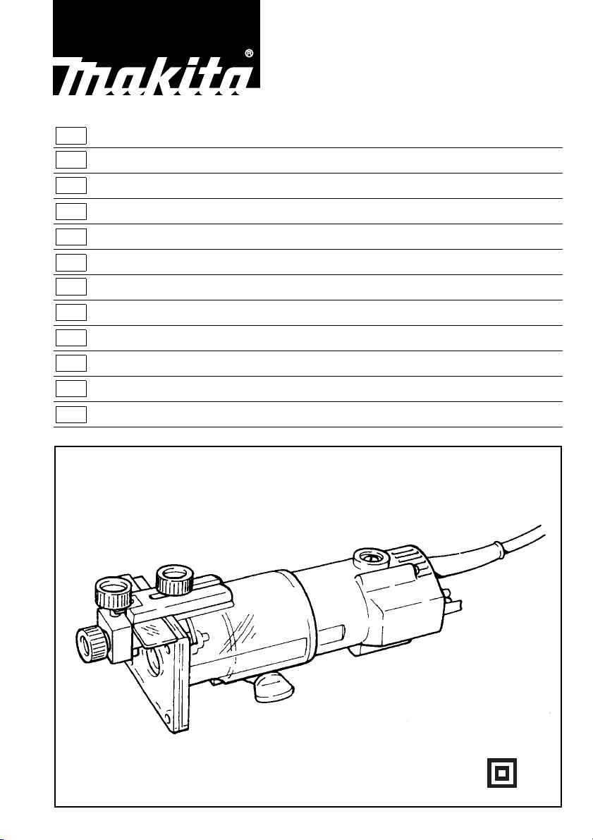
Trimmer Instruction Manual
F
Affleureuse Manuel d’instructions
D
Einhandfräse Betriebsanleitung
I
Rifilatore Istruzioni per l’uso
NL
Kantenfrees Gebruiksaanwijzing
E
Rebordeadora Manual de instrucciones
P
Tupia Manual de instruções
DK
Overfræser Brugsanvisning
S
Kantfräs Bruksanvisning
N
Overfres (Kanttrimmer) Bruksanvisning
SF
Viimeistely-yläjyrsin Käyttöohje
GR Ξακριστή Οδηγίες χρήσεως
3703
12
3
4
5
2
67
89
10 11
12 13
3
14 15
16 17
18 19
37
20
4

ENGLISH
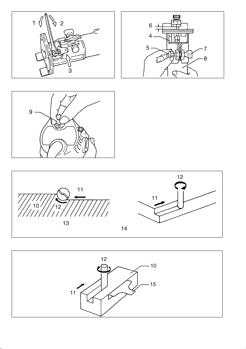
1 Loosen
2Tighten
3Hold
4Base
5 Adjusting screw
6 Bit protrusion
7Nut
8Scale
9 Switch lever
10 Workpiece
11 Feed direction
12 Bit revolving direction
13 View from the top of the tool
Explanation of general view
14 Correct bit feed direction
15 Trimmer shoe, straight guide
or trimmer guide
16 Bolt
17 Guide plate
18 Straight guide
19 Flat washer
20 Wave washer
21 Wing nut
22 Clamp screw (A)
23 Center hole
24 Nail
25 Adjusting screw
26 Clamp screw (B)
27 Trimmer guide
28 Bit
29 Guide roller
30 Screwdriver
31 Base protector
32 Screws
33 Straight bit
34 Templet
35 Distance (X)
36 Templet guide 10
37 Limit mark
38 Brush holder cap
SPECIFICATIONS
Model 3703
Collet chuck capacity....................................6 mm or 1/4”
No load speed (min
Overall length ...................................................... 247 mm
Net weight............................................................... 1.5 kg
• Due to our continuing program of research and development, the specifications herein are subject to change
without notice.
• Note: Specifications may differ from country to country.
Power supp ly
The tool should be connected only to a power supply of
the same voltage as indicated on the nameplate, and can
only be operated on single-phase AC supply. They are
double-insulated in accordance with European Standard
and can, therefore, also be used from sockets without
earth wire.
Safety hints
For your own safety, please refer to the enclosed safety
instructions.
-1
)............................................ 30,000
SPECIFIC SAFETY RULES
GEB019-1
DO NOT let comfort or familiarity with product
(gained from repeated use) replace strict adherence
to trimmer safety rules. If you use this tool unsafely
or incorrectly, you can suffer serious personal injury.
1. Hold power tool by insulated gripping surfaces
when performing an operation where the cutting
tool may contact hidden wiring or its own cord.
Contact with a “live” wire will make exposed
metal parts of the tool “live” and shock the operator.
2. Use clamps or another practical way to secure
and support the workpiece to a stable platform.
Holding the work by hand or against your body
leaves it unstable and may lead to loss of control.
3. Wear hearing protection during extended period
of operation.
4. Handle the bits very carefully.
5. Check the bit carefully for cracks or damage
before operation.
Replace cracked or damaged bit immediately.
6. Avoid cutting nails. Inspect for and remove all
nails from the workpiece before operation.
7. Hold the tool firmly.
8. Keep hands away from rotating parts.
9. Make sure the bit is not contacting the workpiece before the switch is turned on.
10. Before using the tool on an actual workpiece, let
it run for a while.
Watch for vibration or wobbling that could indicate improperly installed bit.
11. Be careful of the bit rotating direction and the
feed direction.
12. Do not leave the tool running. Operate the tool
only when hand-held.
13. Always switch off and wait for the bit to come to
a complete stop before removing the tool from
workpiece.
14. Do not touch the bit immediately after operation;
it may be extremely hot and could burn your
skin.
15. Do not smear the tool base carelessly with thinner, gasoline, oil or the like.
They may cause cracks in the tool base.
16. Draw attention to the need to use cutters of the
correct shank diameter and which are suitable
for the speed of the tool.
17. Some material contains chemicals which may be
toxic. Take caution to prevent dust inhalation
and skin contact. Follow material supplier safety
data.
18. Always use the correct dust mask/respirator for
the material and application you are working
with.
SAVE THESE INSTRUCTIONS.
WARNING:
MISUSE or failure to follow the safety rules stated in
this instruction manual may cause serious personal
injury.
OPERATING INSTRUCTIONS
Installing or removing trimmer bit (Fig. 1)
Important:
Always be sure that the tool is switched off and
unplugged before installing or removing the bit.
Insert the bit all the way into the collet cone and tighten
the collet nut securely with the two wrenches. To remove
the bit, follow the installation procedure in reverse.
5

CAUTION:
• Do not tighten the collet nut without inserting a bit, or
the collet cone will break.
• Use only the wrenches provided with the tool.
Adjusting bit protrusion (Fig. 2)
To adjust the bit protrusion, loosen the nut and move the
tool base up or down as desired by turning the adjusting
screw. After adjusting, tighten the nut firmly to secure the
tool base.
Switch action (Fig. 3)
To start the tool, move the switch lever to the “ON” position. To stop, move the switch lever to the “OFF” position.
Operation
• Set the tool base on the workpiece to be cut without the
bit making any contact. Then turn the tool on and wait
until the bit attains full speed. Move the tool forward
over the workpiece surface, keeping the tool base flush
and advancing smoothly until the cutting is complete.
• When doing edge cutting, the workpiece surface
should be on the left side of the bit in the feed direction.
(Fig. 4)
NOTE:
• Moving the tool forward too fast may cause a poor quality of cut, or damage to the bit or motor. Moving the tool
forward too slowly may burn and mar the cut. The
proper feed rate will depend on the bit size, the kind of
workpiece and depth of cut. Before beginning the cut
on the actual workpiece, it is advisable to make a sample cut on a piece of scrap lumber. This will show
exactly how the cut will look as well as enable you to
check dimensions.
• When using the trimmer shoe, the straight guide or the
trimmer guide, be sure to keep it on the right side in the
feed direction. This will help to keep it flush with the
side of the workpiece. (Fig. 5)
CAUTION:
Since excessive cutting may cause overload of the motor
or difficulty in controlling the tool, the depth of cut should
not be more than 3 mm at a pass when cutting grooves.
When you wish to cut grooves more than 3 mm deep,
make several passes with progressively deeper bit settings.
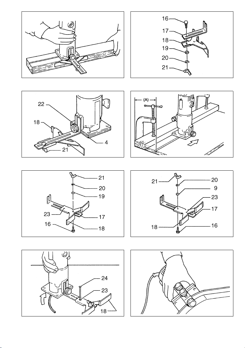
Straight guide
The straight guide is effectively used for straight cuts
when chamfering or grooving. (Fig. 6)
Attach the guide plate to the straight guide with the bolt,
the wave washer, the flat washer and the wing nut.
(Fig. 7)
Remove the chip deflector. Attach the straight guide with
the clamp screw (A). Loosen the wing nut on the straight
guide and adjust the distance between the bit and the
straight guide. At the desired distance, tighten the wing
nut securely. (Fig. 8)
When cutting, move the tool with the straight guide flush
with the side of the workpiece.
If the distance (A) between the side of the workpiece and
the cutting position is too wide for the straight guide, or if
the side of the workpiece is not straight, the straight
guide cannot be used. In this case, firmly clamp a
straight board to the workpiece and use it as a guide
against the trimmer base. Feed the tool in the direction of
the arrow. (Fig. 9)
Circular work
• Circular work may be accomplished if you assemble
the straight guide and guide plate as shown in
Fig. 10 or 11.
Fig. 10 for cutting circles between 70 mm and 121 mm
in radius.
Fig. 11 for cutting circles between 121 mm and
221 mm in radius.
NOTE:
Circles between 172 mm and 186 mm in radius cannot
be cut using this guide.
• Min. and max. radius of circles to be cut (distance
between the center of circle and the center of bit) are
as follows:
Min.: 70 mm
Max.: 221 mm
Align the center hole in the straight guide with the center
of the circle to be cut. Drive a nail less than 6 mm in
diameter into the center hole to secure the straight guide.
Pivot the tool around the nail in clockwise direction.
(Fig. 12)
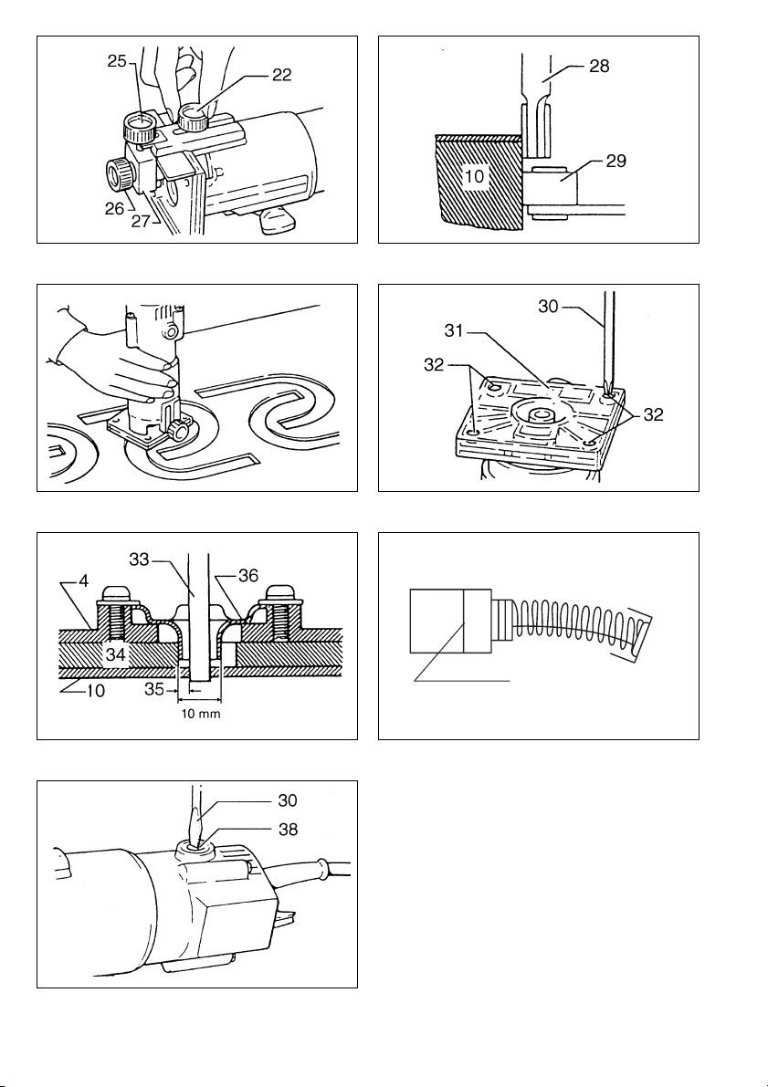
Trimmer guide
Trimming, curved cuts in veneers for furniture and the like
can be done easily with the trimmer guide. The guide
roller rides the curve and assures a fine cut. (Fig. 13)
Install the trimmer guide on the tool base with the clamp
screw (A). Loosen the clamp screw (B) and adjust the
distance between the bit and the trimmer guide by turning the adjusting screw (1 mm per turn). At the desired
distance, tighten the clamp screw (B) to secure the trimmer guide in place. (Fig. 14)
When cutting, move the tool with the guide roller riding
the side of the workpiece. (Fig. 15)
Templet guide
The templet guide provides a sleeve through which the bit passes, allowing use of the trimmer with templet patterns.
(Fig. 16)
Remove the chip deflector. Loosen the screws and remove the base protector. Place the templet guide on the base
and replace the base protector. Then secure the base protector by tightening the screws. (Fig. 17)
Secure the templet to the workpiece. Place the tool on the templet and move the tool with the templet guide sliding
along the side of the templet. (Fig. 18)
6

NOTE:
The workpiece will be cut a slightly different size from the templet. Allow for the distance (X) between the router bit and
the outside of the templet guide. The distance (X) can be calculated by using the following equation:
Distance (X) =
outside diameter of the templet guide – router bit diameter
2
MAINTENANCE
CAUTION:
Always be sure that the tool is switched off and
unplugged before carrying out any work on the tool.
Replacement of carbon brushes (Fig. 19 & 20)
Replace carbon brushes when they are worn down to the
limit mark. Both identical carbon brushes should be
replaced at the same time.
To maintain product safety and reliability, repairs, maintenance or adjustment should be carried out by a Makita
Authorized Service Center.
7

NEDERLANDS
1 Losdraaien
2 Vastdraaien
3 Vasthouden
4 Zoolplaat
5 Afstelschroef
6 Gewenste snijdiepte
7Moer
8Schaal
9 Schakelaar
10 Werkstuk
11 Trimrichting
12 Rotatierichting van het frees
13 Van bovenaf gezien
Verklaring van algemene gegevens
14 Juiste rotatie-en trimrichting
15 Trimschoen, rechte geleider of
trimgeleider
16 Bout
17 Geleideplaat
18 Rechte geleider
19 Platte vulring
20 Golf vulring
21 Vleugelmoer
22 Klampschroef (A)
23 Middengaatje
24 Spijker
25 Afstelschroef
26 Klampschroef (B)
27 Trimgeleider
28 Frees
29 Rol van geleider
30 Schroevedraaier
31 Zoolplaatbeschermer
32 Schroef
33 Recht freesmes
34 Sjabloon
35 Afstand (X)
36 Sjabloongeleider
37 Limiet
38 Kap van koolborstelhouder
TECHNISCHE GEGEVENS
Model 3703
Spantang cap. .............................................6 mm of 1/4”
Toerental onbelast (min
Totale lengte .......................................................247 mm
Netto gewicht ......................................................... 1,5 kg
• In verband met ononderbroken research en ontwikkeling behouden wij ons het recht voor bovenstaande
technische gegevens te wijzigen zonder voorafgaande
kennisgeving.
• Opmerking: De technische gegevens kunnen van land
tot land verschillen.
Stroomvoorziening
Het gereedschap mag alleen worden aangesloten op
een stroombron van hetzelfde voltage als aangegeven op
de naamplaat, en kan alleen op enkel-fase wisselstroom
worden gebruikt. Het gereedschap is dubbel-geïsoleerd
volgens de Europese standaard en kan derhalve ook op
een niet-geaard stopkontakt worden aangesloten.
Veiligheidswenken
Voor uw veiligheid dient u de bijgevoegde Veiligheidsvoorschriften nauwkeurig op te volgen.
–1
) ....................................30 000
AANVULLENDE
VEILIGHEIDSVOORSCHRIFTEN
Laat u NIET misleiden door een vals gevoel van comfort en bekendheid met het gereedschap (na veelvuldig gebruik) en neem alle veiligheidsvoorschriften
van de trimmer altijd strikt in acht. Bij onveilig of verkeerd gebruik van het elektrisch gereedschap,
bestaat de kans op ernstig persoonlijk letsel.
1. Houd elektrisch gereedschap vast aan het geïso-
leerde oppervlak van de handgrepen wanneer u
werkt op plaatsen waar het zaaggereedschap
met verborgen bedrading of zijn eigen snoer in
aanraking kan komen. Door contact met onder
spanning staande draden, zullen de niet-geïsoleerde metalen delen van het gereedschap onder
spanning komen te staan zodat de gebruiker een
elektrische schok kan krijgen.
2. Gebruik klemmen of een andere praktische
methode om het werkstuk op een stabiele ondergrond te bevestigen en ondersteunen. Als u het
werkstuk in uw hand of tegen uw lichaam
geklemd houdt, is het onvoldoende stabiel en
kunt u de controle erover verliezen.
3. Gebruik een oorbescherming, wanneer U lange
tijd met dit gereedschap denkt te werken.
4. Wees voorzichtig met het frees.
5. Kontroleer het frees op barsten of beschadiging,
alvorens het gereedschap in te schakelen en vervang onmiddellijk als het frees is gebarsten of
beschadigd.
6. Zorg dat het frees niet in kontakt komt met spijkers enz. Verwijder derhalve alvorens met trimmen te beginnen eventuele spijkers en dergelijke
van het werkstuk.
7. Houd het gereedschap stevig vast.
8. Houd uw handen uit de buurt van de roterende
delen.
9. Zorg dat het frees niet in kontakt is met het werkstuk wanneer u het gereedschap inschakelt.
10. Laat het gereedschap draaien, alvorens het
werkstuk te trimmen.
Kontroleer of er trillingen en/of schommelingen
zijn, die op een verkeerd geinstalleerd frees kunnen wijzen.
11. Zorg dat de rotatierichting overeenkomt met de
trimrichting.
12. Schakel het gereedschap onmiddellijk uit, als u
het niet meer gebruikt. Schakel het gereedschap
allen in, als u het in handen houdt.
13. Schakel het gereedschap uit en wacht tot het
helemaal tot stilstand is gekomen, alvorens het
van het werkstuk te verwijderen.
14. Raak het frees onmiddelijk na het trimmen niet aan;
aangezien het nog gloeiend heet is en derhalve
brandwonden kan veroorzaken.
15. Wees voorzichtig en veeg het voetstuk van het
gereedschap niet af met verfverdunner, benzine,
olie of iets dergelijks, aangezien er anders barsten in kunnen komen.
16. Zorg ervoor dat u uitsluitend frezen gebruikt die
de juiste schachtdiameter hebben en geschikt
zijn voor de snelheid van het gereedschap.
17. Sommige materialen bevatten chemische stoffen
die vergiftig kunnen zijn. Vermijd inademing van
stof en contact met de huid. Volg de veiligheidsinstructies van de leverancier van het materiaal.
18. Gebruik altijd het juiste stofmasker/ademhalingsapparaat voor het materiaal en de toepassing waarmee u werkt.
BEWAAR DEZE VOORSCHRIFTEN.
17
 Loading...