Angle Tool Base Can Be Changed – 5 degree per graduation.
Trimmer shoe, straight guide and trimmer guide are included.
Replacement parts and accessories are available.
Frequently Asked Questions
Q: What is the collet chuck capacity of the device?
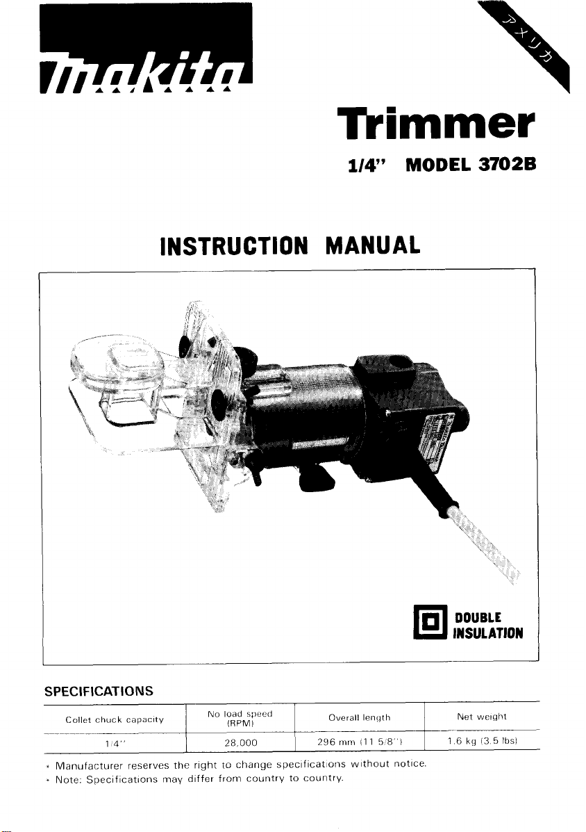
A: Collet chuck capacity is 1/4”.
Q: What is the free speed of no load on this trimmer?
A: The highest speed at no load is: 28000 rpm.
Q: What is the overall length of the device?
A: Its overall length is 296 mm~(11.5\'\').
Q: What is the weight of the trimmer?
A: Its net weight is 1.6 kg~(3.5 lbs).
Q: Is there a double insulation on the device?
A: The device has a double insulation features.
Q: Is it possible to make an adjustment of the bit protrusion?
Q: Yes. Yes, it is possible to adjust the bit protrusion.
Q: What is the purpose of the straight guide that comes with the trimmer? A: The purpose of the straight guide is to make straight cuts when chamfering or grooving. Q: What safety precautions should be taken while using the trimmer? A: Never use the trimmer without safety glasses, switch off the tool when it is not in use, read all instructions and keep the work area tidy at all times. Q: For this device, are replacement parts available? A: Yes replacement parts and accessories compatible with this device are available.
User Manual
Page 1
Tkimmer
1/4”
MODEL
INSTRUCTION MANUAL
3702B
SPECIFICATIONS
Collet
chuck
_~____~__
capacity
14
No
load
(RPMI
28
000
speed
Overall
296
mm
lenqth
11
1
DOUBLE
INSULATION
Net
weight
-
5
8
1
1
6
kg
13
5
lbsl
Page 2
IMPORTANT
SAFETY INSTRUCTIONS
(For
All Tools)
WARNING:
WHEN USING ELECTRIC TOOLS, BASIC SAFETY PRECAUTIONS SHOULD ALWAYS BE FOLLOWED TO
REDUCE THE RISK OF FIRE, ELECTRIC SHOCK, AND PERSONAL INJURY, INCLUDING THE FOLLOWING:
READ ALL INSTRUCTIONS.
1.
KEEP WORK AREA CLEAN. Cluttered areas and benches invite injuries.
2.
CONSIDER WORK AREA ENVIRONMENT. Don’t use power tools in damp
or wet locations. Keep work area well
in
Don’t use tool
KEEP CHILDREN AWAY.
3.
Don’t let visitors contact tool or extension cord.
4.
STORE IDLE TOOLS. When not
or locked-up place - out of reach of children.
DON’T FORCE TOOL.
5.
it
was intended.
USE RIGHT TOOL. Don‘t force small tool or attachment to do the job of a
6.
heavy-duty tool. Don’t use tool for purpose not intended.
DRESS PROPERLY. Don’t wear loose clothing or jewelry. They can be caught
7.
in moving parts. Rubber gloves and non-skid footwear are recommended
when working outdoors. Wear protective hair covering to contain long hair.
USE SAFETY GLASSES. Also use face or dust mask if cutting operation is
8.
dusty.
DON’T ABUSE CORD. Never carry tool by cord or yank
9.
receptacle. Keep cord from heat, oil, and sharp edges.
IO.
SECURE WORK. Use clamps or a vise to hold work. It’s safer than using
your hand and
DON’T OVERREACH. Keep proper footing and balance at all times.
11.
MAINTAIN TOOLS WITH CARE. Keep tools sharp and clean for better and
12.
safer performance. Follow instructions for lubricating and changing accessories. Inspect tool cords periodically and if damaged, have repaired by authorized service facility. Inspect extension cords periodically and replace if
damaged. Keep handles dry, clean, and free from oil and grease.
DISCONNECT TOOLS. When not
13.
ing accessories, such as blades, bits, cutters.
presence of flammable liquids or gases.
All
visitors should be kept away from work area.
in
It
will
do the job better and safer at the rate for which
it
frees both hands to operate tool.
lit.
Don’t expose power tools to rain.
use, tools should be stored
in
use, before servicing, and when chang-
in
dry, and high
it
to disconnect from
2
Page 3
14.
REMOVE ADJUSTING KEYS AND WRENCHES. Form habit of checking to
see that keys and adjusting wrenches are removed from tool before turning
it
on.
15.
AVOID UNINTENTIONAL STARTING. Don't carry plugged-in tool
on switch. Be sure switch is
16.
OUTDOOR USE EXTENSION CORDS. When tool is used outdoors, use only
extension cords intended for use outdoors and
17.
STAY
ALERT.
tool when you are tired.
18.
CHECK DAMAGED PARTS. Before further use
part that is damaged should be carefully checked to determine that
operate properly and perform its intended function. Check for alignment of
moving parts,
other conditions that may affect its operation. A guard or other part that
is damaged should be properly repaired or replaced
ice center unless otherwise indicated elsewhere
Have defective switches replaced by authorized service center. Don't use
tool if switch does not turn
19.
GUARD AGAINST ELECTRIC SHOCK. Prevent body contact
surfaces. For example; pipes, radiators, ranges, refrigerator enclosures.
20.
REPLACEMENT PARTS. When servicing, use only identical replacement parts.
VOLTAGE WARNING: Before connecting the tool to a power source (receptacle,
outlet, etc.) be sure the voltage supplied is the same as that specified on the
nameplate of the tool. A power source
for the tool can result in SERIOUS INJURY to the user
the tool. If
voltage less than the nameplate rating is harmful to the motor.
in
Watch
binding
doubt,
what
of moving parts, breakage of parts, mounting, and any
DO
NOT PLUG IN THE TOOL. Using a power source with
OFF
when plugging
you
are doing, use common sense. Don't operate
it
on and off.
with
voltage greater than that specified
in.
so
marked.
of
the tool, a guard or other
by
an authorized serv-
in
this instruction manual.
-
as well as damage to
with
with
finger
it
grounded
will
3
Page 4
ADDITIONAL SAFETY RULES
1.
Wear hearing protection during extended periods of operation.
2.
Handle the bits very carefully.
3.
Check the bit carefully for cracks or damage before operation.
Replace cracked or damaged bit immediately.
4.
Avoid cutting nails. Inspect for and remove all nails from the workpiece
before operation.
5.
Hold the tool firmly.
6.
Keep hands away from rotating parts.
7.
Make sure the
on.
8.
Before using the tool on an actual workpiece, let
Watch for vibration or wobbling that could indicate improperly installed bit.
9.
Be careful of the bit rotating direction and the feed direction.
IO.
Do not leave the tool running. Operate the tool only when hand-held.
11.
Always switch off and wait for the bit to come to a complete stop before
removing the tool from workpiece.
12.
Do not touch the
and could burn your skin.
13.
Don't smear the tool base carelessly with thinner, gasoline, oil or the like.
They may cause cracks
bit
is not contacting the workpiece before the switch is turned
it
run for a while.
bit
immediately after operation;
in
the tool base.
it
may be extremely hot
SAVE
4
THESE INSTRUCTIONS.
Page 5
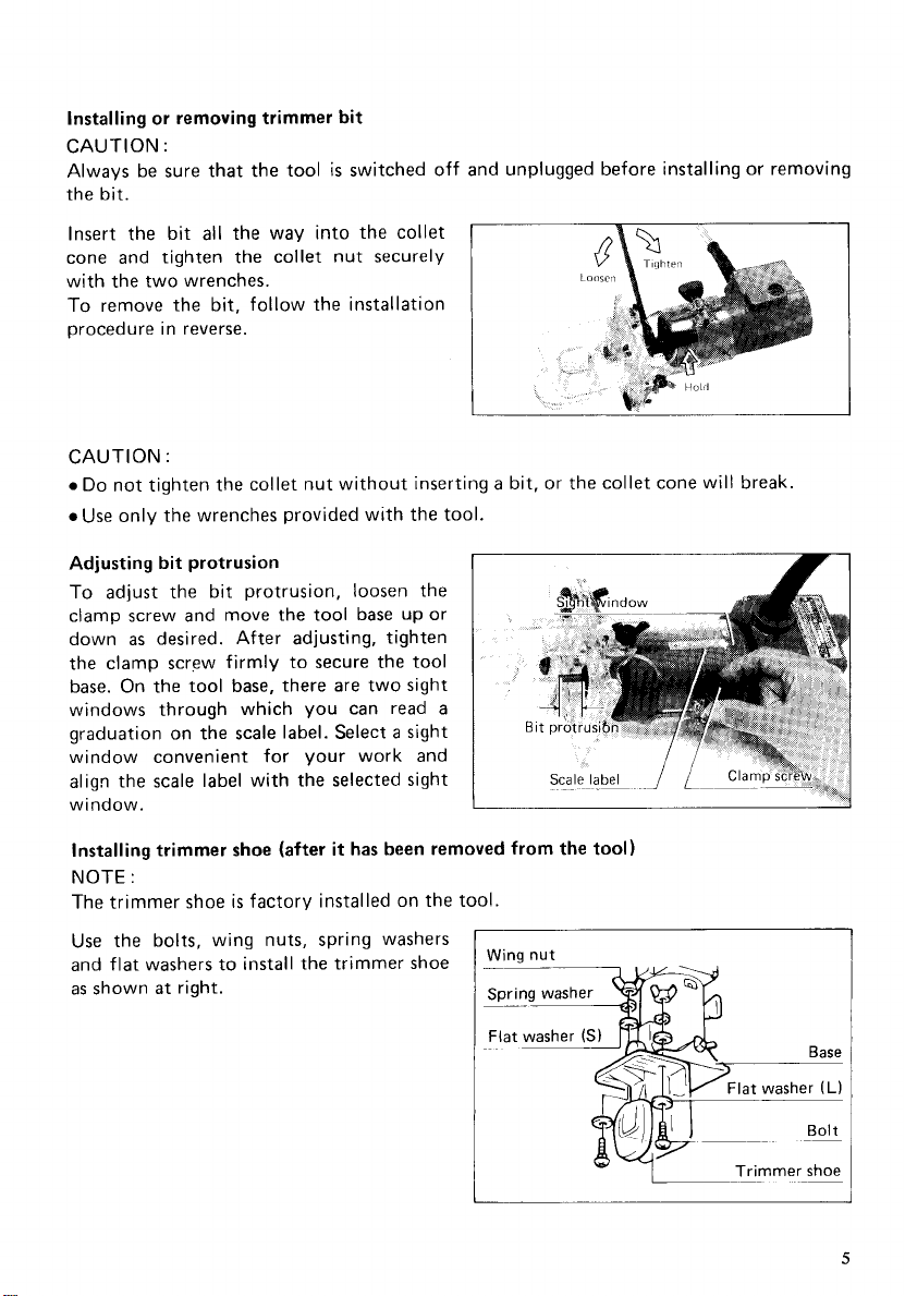
Installing or removing trimmer bit
CAUTION
Always be sure that the tool
:
is
switched off and unplugged before installing or removing
the bit.
all
Insert the bit
the way into the collet
cone and tighten the collet nut securely
with the two wrenches.
To
remove the bit, follow the installation
procedure in reverse.
CAUTION
0
Do
0
Use only the wrenches provided with the tool.
:
not tighten the collet nut without inserting a bit, or the collet cone will break.
Adjusting bit protrusion
To
adjust the bit protrusion, loosen the
clamp screw and move the tool base up or
as
down
desired. After adjusting, tighten
the clamp screw firmly to secure the tool
base. On the tool base, there are two sight
windows through which you can read
a
graduation on the scale label. Select a sight
window convenient for your work and
align the scale label with the selected sight
window.
installing trimmer shoe (after it has been removed from the tool)
NOTE
:
The trimmer shoe
Use the bolts, wing nuts, spring washers
and flat washers to install the trimmer shoe
as
shown
at
right.
is
factory installed on the tool.
Wing
nut
______~~
Trimmer
~~
shoe
5
Page 6
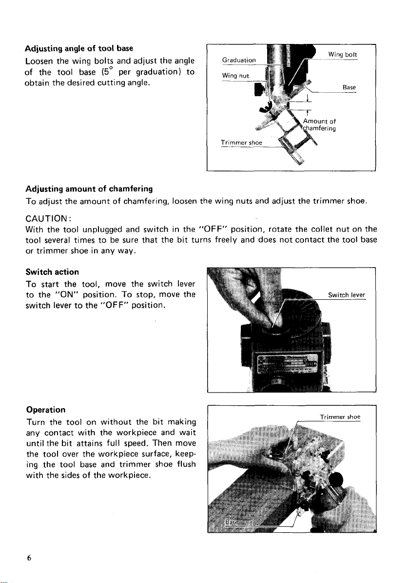
Adjusting angle of tool base
Loosen the wing bolts and adjust the angle
of
the tool base
(5'
per graduation) to
obtain the desired cutting angle.
-
Gradual
__
Wing nut
Wing bolt
~___
Base
It
of
ring
Adjusting amount of chamfering
To adjust the amount of chamfering, loosen the wing nuts and adjust the trimmer shoe.
CAUTION
With the tool unplugged and switch in the
:
"OFF"
position, rotate the collet nut on the
tool several times to be sure that the bit turns freely and does not contact the tool base
or trimmer shoe in any way.
Switch action
To start the tool, move the switch
to the
switch lever to the
"ON"
position.
"OFF"
To
stop, move the
position.
lever
Operation
Turn the tool on without the bit making
any contact with the workpiece and wait
until the bit attains full speed. Then move
the tool over the workpiece surface, keeping the tool base and trimmer shoe flush
of
with the sides
the workpiece.
6
Page 7
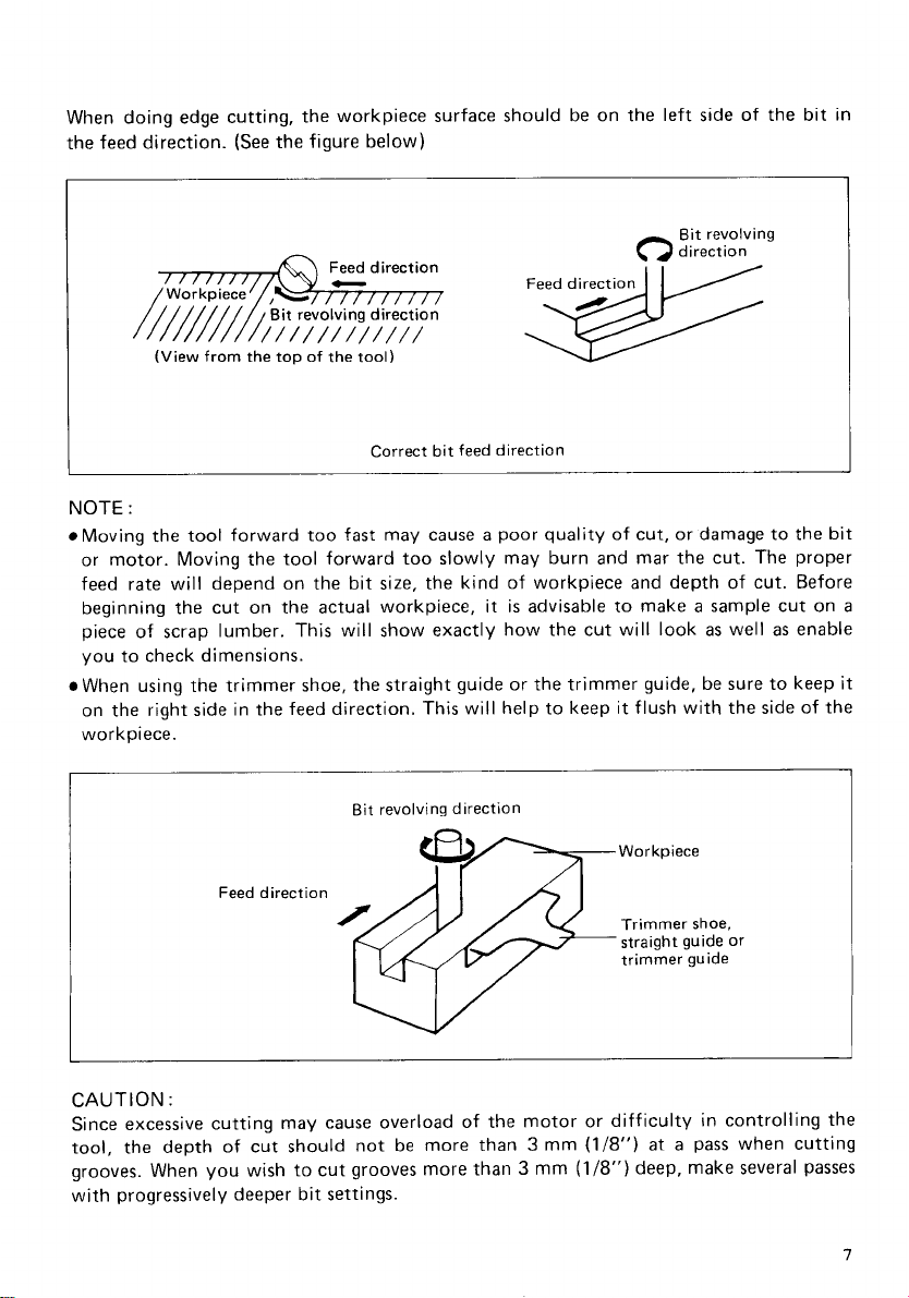
When doing edge cutting, the workpiece surface should be on the left side
the feed direction.
(See
the figure below)
Feed direction
Feed direction
Bit revolving
direction
of
the bit in
NOTE
(View from the top of the tool)
Correct bit feed
:
2w
direction
Moving the tool forward too fast may cause a poor quality of cut, or damage to the bit
or motor. Moving the tool forward too slowly may burn and mar the cut. The proper
rate
feed
beginning the cut on the actual workpiece, it
piece of scrap lumber. This will show exactly how the cut will look
will depend on the bit size, the kind of workpiece and depth of cut. Before
is
advisable to make a sample cut on
as
well
as
enable
you to check dimensions.
When using the trimmer shoe, the straight guide or the trimmer guide, be sure to keep
on the right side in the feed direction. This will help to keep it flush with the side of the
workpiece.
Bit revolving direction
Workpiece
Feed direction
Trimmer shoe,
straight guide or
trimmer guide
a
it
I
CAUTION
:
Since excessive cutting may cause overload of the motor or difficulty in controlling the
3
mm
(1/8")
at
a
tool, the depth of cut should not be more than
grooves. When you wish to cut grooves more than 3 mm
(1/8")
pass when cutting
deep, make several passes
with progressively deeper bit settings.
Page 8
Straight guide
The straight guide
straight cuts when chamfering or grooving.
Attach the guide plate to the straight guide
with the bolt, the wave washer, the flat
washer and the wing nut.
is
effectively used for
Flat washer
Wave
I
washer
U
Loosen the wing bolts and secure the tool
base horizontally. Attach the straight guide
with the clamp screw (A). Loosen the wing
nut on the straight guide and adjust the
distance between the bit and the straight
guide. At the desired distance, tighten the
wing nut securely.
When cutting, move the tool with the straight guide flush with the side of the workpiece.
8
Page 9
Circular
0Circular work may be accomplished if you assemble the straight guide and guide plate
0
(Note)
Circles between 172 mm (6-3/4") and 186 mm (7-5/16") in radius cannot be cut using
this guide.
work
as
shown in the figure below.
Min. and max. radius
center
of
bit) are
Min. : 70 mm (2-3/4")
Max.
:
221 mm (8-11/16")
as
follows
of
circles to be cut (distance between the center
:
Wave washer
of
circle and the
Wing nut
Flat washer
Bolt
__
For cutting circles between 70 mm (2-3/4")
and 121 mm (4-3/4") in radius.
Align the center hole in the straight guide
with the center
Drive a nail
diameter into the center hole to secure the
straight guide. Pivot the tool around the
nail in clockwise direction.
of
the circle to be cut.
less
than 6 mm (1/4") in
:
IV
I
For cutting circles between 121
and 221 mm (8-1 1/16") in radius.
i_
Flat washer
Center
hole
Guide plate
Straight guide
Bo1
~
mm
(4-3/4")
Straight guide
t
9
Page 10
Trimmer
guide
Trimming, curved cuts for furniture and the
like can be done easily with the trimmer
guide. The guide roller rides the curve and
a
assures
fine cut.
Loosen the wing bolts and secure the tool
base horizontally. Install the trimmer guide
on the tool base with the clamp screw
Loosen the clamp screw
(6)
and adjust the
(A).
distance between the bit and the trimmer
(1
guide by turning the adjusting screw
3/64"
or about
per turn). At the desired
distance, tighten the clamp screw
mm
(6)
to
secure the trimmer guide in place.
When cutting, move the tool with the guide
of
roller riding the side
10
the workpiece.
Clamp
screw
(6)
,
I
Page 11
Templet
The templet guide provides
guide
a
sleeve
through
which the bit passes, allowing use of the
trimmer with templet patterns.
Remove the tool base from the tool.
Loosen the wing bolts and secure the tool
base horizontally. Loosen the two screws
on the tool base.
Place the templet guide on the tool base.
There are four convex portions on the templet guide. Secure two of the four convex
portions using the two screws. Install the
tool base on the tool.
Base
I
J
Convex
portions
11
Page 12
Secure the templet to the workpiece.
Place
the tool on the templet and move the tool
with the templet guide sliding along the
side of the templet.
I
Straight
bit
Base
I.
I
Templet guide
r
I
\
NOTE
:
The workpiece will be cut a slightly different
tance
(X)
between the router bit and the outside of the templet guide. The distance
can be calculated
Distance
(X)
by
using the following equation
=
outside diameter of the templet guide - router bit diameter
2
Distance
L
size
:
(X)
Workpiece
10
(25/64")
from the templet. Allow
mm
for
the dis-
(X)
12
Page 13
MAINTENANCE
CAUTION
Always be sure that the tool
inspection or maintenance.
:
is
switched off and unplugged before attempting
to
perform
Replacing carbon brushes
Remove and check the carbon brushes
regularly. Replace when they wear down to
the limit mark. Keep the carbon brushes
clean
and free
carbon brushes should be replaced
same time. Use only Makita carbon brushes.
a
Use
holder caps. Take out the worn carbon
brushes, insert the new ones and secure the
brush holder caps.
screwdriver to remove the brush
to
slip in
the
holders. Both
at
the
I
To
maintain product SAFETY and RELIABILITY, repairs, any other maintenance or
adjustment should be performed by Makita Authorized or Factory Service Centers,
always using Makita replacement parts.
13
Page 14
ACCESS0 R I
CAUTION
These accessories or attachments are recommended for use with your Makita tool specified in this
manual. The use
The accessories or attachments should be used only in the proper and intended manner.
Every Makita tool
be free of defects from workmanship and materials for the period of ONE YEAR from the date of
original purchase. Should any trouble develop during this one-year period, return the COMPLETE
tool, freight prepaid, to
the trouble is caused by defective workmanship or material, Makita will repair (or at our option,
replace) without charge.
This Warranty does not apply where:
8
repairs have been made or attempted by others:
repairs are required because of
The tool has been abused, misused or improperly maintained;
alterations have been made to the tool.
IN NO EVENT SHALL MAKITA BE LIABLE FOR ANY INDIRECT, INCIDENTAL
SEQUENTIAL DAMAGES FROM THE SALE
APPLIES BOTH DURING AND AFTER THE TERM
MAKITA DISCLAIMS LIABILITY FOR ANY IMPLIED WARRANTIES, INCLUDING IMPLIED
WARRANTIES OF “MERCHANTABILITY” AND “FITNESS FOR A SPECIFIC PURPOSE,”
AFTER THE ONE-YEAR TERM OF THIS WARRANTY.
This Warranty gives you specific legal rights, and you may also have other rights which vary from
state to state. Some states do not allow the exclusion or Limitation of incidental or consequential
damages,
limitation
IS
thoroughly inspected and tested before leaving the factory. It
one
of Makita’s Factory or Authorized Service Centers. If inspection shows
normal
wear and tear:
so
the above limitation or exclusion may not apply to you. Some states do not allow
on
how
long
an implied warranty lasts,
Policy
OR
USE
OF
THE PRODUCT. THIS DISCLAIMER
OF
THIS WARRANTY.
so
the above limitation may not apply to you.
IS
warranted to
OR
CON-
Makita Corporation
3-11
-8,
Sumiyoshi-cho,
Anjo, Aichi
446
Japan
883678A064
PRINTED IN JAPAN
1991
-
11
-
N
Loading...
+ hidden pages
You need points to download manuals.
1 point = 1 manual.
You can buy points or you can get point for every manual you upload.


 Loading...