

Page 1
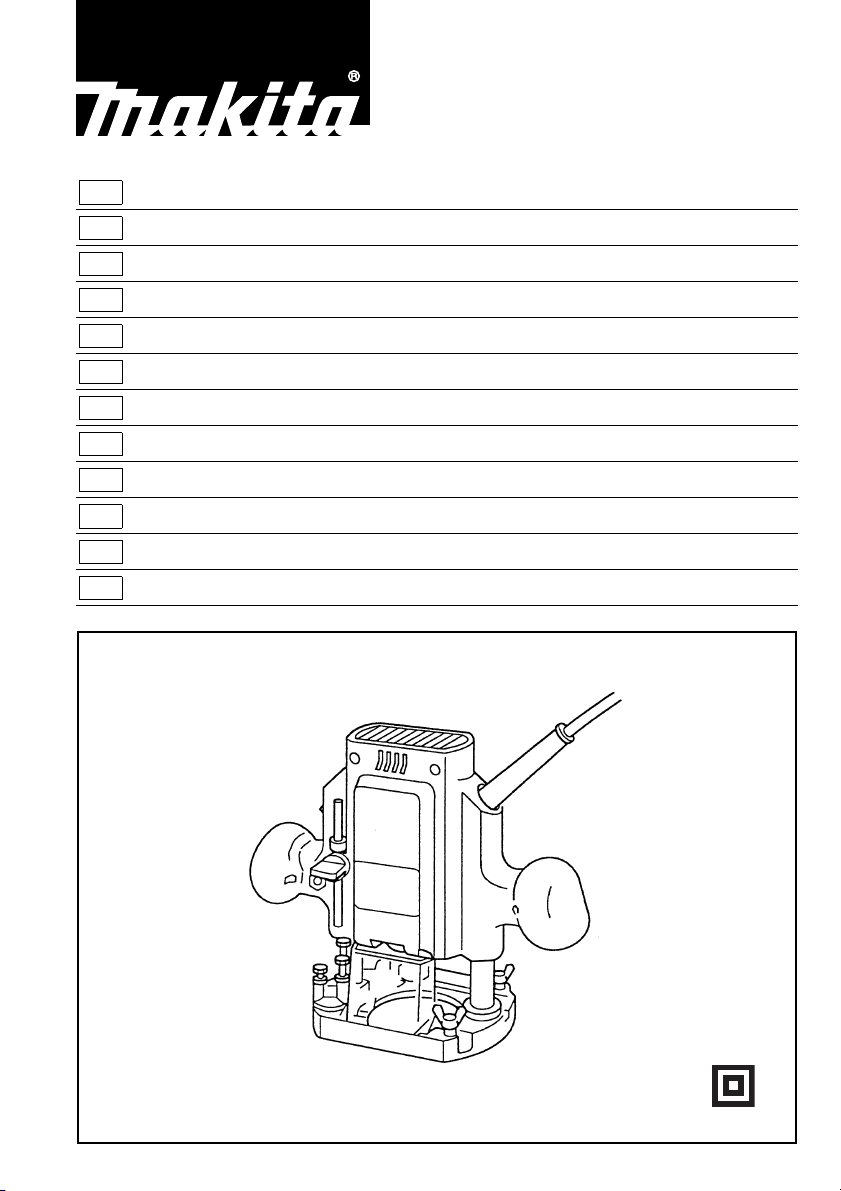
GB Router
Instruction Manual
F Défonceuse
DOberfräse
I Fresatrice
NL Bovenfrees
E Fresadora
P
Tupia Manual de instruções
DK
Overfr
S
Hand
NHåndoverfres
SF
Yläjyrsin Käyttöohje
GR Ρούτερ Οδηγίες χρήσεως
æser
överfräs
Manuel d’instructions
Betriebsanleitung
Istruzioni per l’uso
Gebruiksaanwijzing
Manual de instrucciones
Brugsanvisning
Bruksanvisning
Bruksanvisning
3620
Page 2

12
34
56
7
2
Page 3
8
910
11 12
13 14
3
Page 4
15 16
17
4
Page 5

ENGLISH
1Tighten
2Loosen
3Hold
4Screw
5 Stopper pole
6Lock lever
7 Depth pointer
8 Adjusting hex bolt
9 Stopper block
Explanation of general view
10 Hex nut
11 Switch trigger
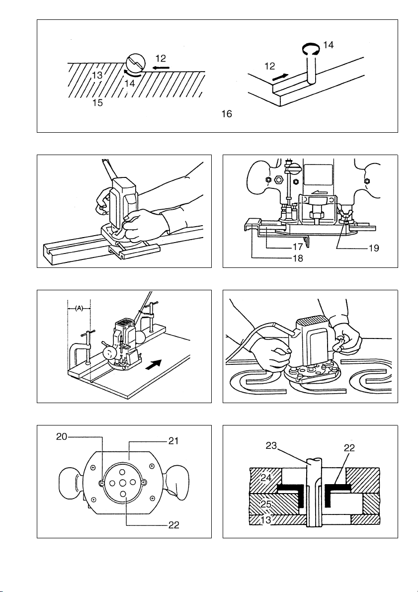
12 Feed direction
13 Workpiece
14 Bit revolving direction
15 (View from the top of the tool)
16 Correct bit feed direction
17 Guide bar
18 Straight guide
19 Wing bolt
20 Screw
21 Base plate
22 Templet guide
23 Bit
24 Base
25 Templet
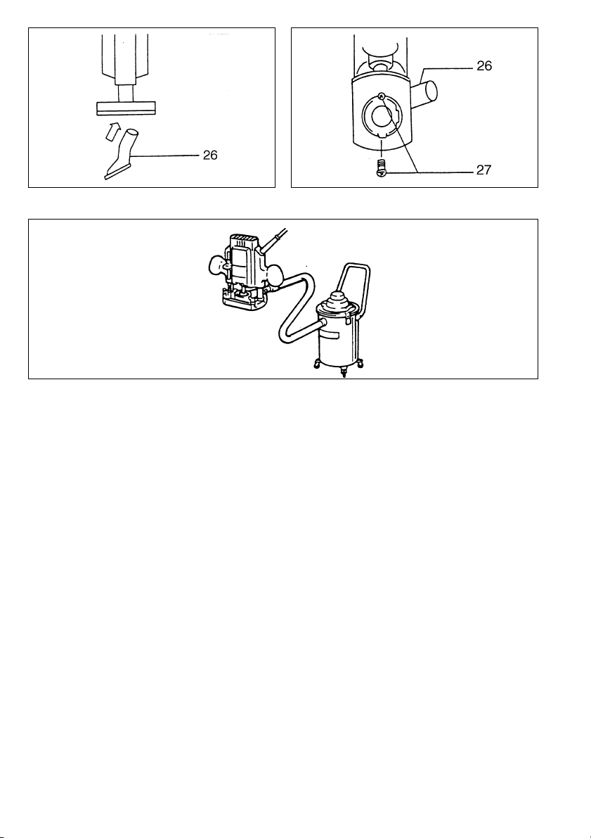
26 Vacuum head
27 Screws
SPECIFICATIONS
Model 3620
Collet capacity ............................................ .8 mm or 3/8”
Plunge capacity ............................................... 0 – 35mm
No load speed (min
Overall height ..................................................... 211 mm
Net weight .............................................................. 2.4 kg
• Due to our continuing program of research and development, the specifications herein are subject to change
without notice.
• Note: Specifications may differ from country to country.
Power supply
The tool should be connected only to a power supply of
the same voltage as indicated on the nameplate, and can
only be operated on single-phase AC supply. They are
double-insulated in accordance with European Standard
and can, therefore, also be used from sockets without
earth wire.
Safety hints
For your own safety, please refer to the enclosed safety
instructions.
-1
) ........................................... 29,000
SPECIFIC SAFETY RULES
GEB018-1
DO NOT let comfort or familiarity with product
(gained from repeated use) replace strict adherence
to router safety rules. If you use this tool unsafely or
incorrectly, you can suffer serious personal injury.
1. Hold power tool by insulated gripping surfaces
when performing an operation where the cutting
tool may contact hidden wiring or its own cord.
Contact with a “live” wire will make exposed
metal parts of the tool “live” and shock the operator.
2. Use clamps or another practical way to secure
and support the workpiece to a stable platform.
Holding the work by hand or against your body
leaves it unstable and may lead to loss of control.
3. Wear hearing protection during extended period
of operation.
4. Handle the bits very carefully.
5. Check the bit carefully for cracks or damage
before operation.
Replace cracked or damaged bit immediately.
6. Avoid cutting nails. Inspect for and remove all
nails from the workpiece before operation.
7. Hold the tool firmly.
8. Keep hands away from rotating parts.
9. Make sure the bit is not contacting the workpiece before the switch is turned on.
10. Before using the tool on an actual workpiece, let
it run for a while.
Watch for vibration or wobbling that could indicate improperly installed bit.
11. Be careful of the bit rotating direction and the
feed direction.
12. Do not leave the tool running. Operate the tool
only when hand-held.
13. Always switch off and wait for the bit to come to
a complete stop before removing the tool from
workpiece.
14. Do not touch the bit immediately after operation;
it may be extremely hot and could burn your
skin.
15. Do not smear the tool base carelessly with thinner, gasoline, oil or the like.
They may cause cracks in the tool base.
16. Draw attention to the need to use cutters of the
correct shank diameter and which are suitable
for the speed of the tool.
17. Some material contains chemicals which may be
toxic. Take caution to prevent dust inhalation
and skin contact. Follow material supplier safety
data.
18. Always use the correct dust mask/respirator for
the material and application you are working
with.
SAVE THESE INSTRUCTIONS.
WARNING:
MISUSE or failure to follow the safety rules stated in
this instruction manual may cause serious personal
injury.
OPERATING INSTRUCTIONS
Installing or removing router bit (Fig.1)
Important:
Always be sure that the tool is switched off and
unplugged before installing or removing the bit.
Insert the bit all the way into the collet cone and tighten
the collet nut securely with the two wrenches.
A 6 mm or 1/4” collet cone is also provided as standard
equipment besides the 8mm or 3/8” collet cone that is
factory installed on the tool. Use the correct size collet
cone for the bit which you intend to use.
To remove the bit, follow the installation procedure in
reverse.
5
Page 6

CAUTION:
Do not tighten the collet nut without inserting a bit, or the
collet cone will break.
Adjusting the depth of cut (Fig. 2, 3 & 4)
Place the tool on a flat surface. Loosen the screw securing the stopper pole.
Loosen the lock lever and lower the tool body until the bit
just touches the flat surface. Tighten the lock lever to lock
the tool body.
Next, lower the stopper pole until it makes contact with
the adjusting hex bolt. Align the depth pointer with the “0”
graduation.
Raise the stopper pole until the desired depth of cut is
obtained. The depth of cut is indicated on the scale
(1 mm or 1/16” per graduation) by the depth pointer.
Then tighten the screw to secure the stopper pole.
Now, your predetermined depth of cut can be obtained by
loosening the lock lever and then lowering the tool body
until the stopper pole makes contact with the adjusting
hex bolt.
CAUTION:
Since excessive cutting may cause overload of the motor
or difficulty in controlling the tool, the depth of cut should
not be more than 15 mm at a pass when cutting grooves
with an 8 mm diameter bit.
[Note: When cutting grooves with a 20 mm diameter bit,
the depth of cut should not be more than 5 mm at a
pass.] When you wish to cut grooves more than 15 mm
deep with an 8 mm diameter bit or more than 5 mm deep
with a 20 mm diameter bit, make several passes with
progressively deeper bit settings.
Stopper block (Fig. 5)
The stopper block has three adjusting hex bolts which
raise or lower 0.8 mm per turn. You can easily obtain
three different depths of cut using these adjusting hex
bolts without readjusting the stopper pole.
Adjust the lowest hex bolt to obtain the deepest depth of
cut, following the method of “Adjusting depth of cut”.
Adjust the two remaining hex bolts to obtain shallower
depths of cut. The differences in height of these hex bolts
are equal to the differences in depths of cut. To adjust the
hex bolts, first loosen the hex nuts on the hex bolts with
the wrench and then turn the hex bolts. After obtaining
the desired position, tighten the hex nuts while holding
the hex bolts in that desired position. The stopper block is
also convenient for making three passes with progressively deeper bit settings when cutting deep grooves.
CAUTION:
When using a bit having total length of 60 mm or more, or
edge length of 35 mm or more, the depth of cut cannot
be adjusted as previously mentioned. To adjust, proceed
as follows:
Loosen the lock lever and carefully adjust bit protrusion
below the tool base to the desired depth of cut by moving
the tool body up or down. Then re-tighten the lock lever
to lock the tool body at that depth of cut. Keep the tool
body locked at this position during use. Since the bit
always protrudes from the tool base, be careful when
handling the tool.
Adjusting the lock lever (Fig. 6)
The locked position of the lock lever is adjustable. To
adjust it, loosen the lock lever 3/4 turn and press the center of the lock lever. The hex nut will come out. Set the
hex nut to the desired position and tighten the lock lever.
Switch action (Fig. 7)
CAUTION:
Before plugging in the tool, always check to see that the
switch trigger actuates properly and returns to the “OFF”
position when released.
To start the tool, simply pull the trigger. Release the trigger to stop.
Operation (Fig. 8)
• Set the tool base on the workpiece to be cut without the
bit making any contact. Then turn the tool on and wait
until the bit attains full speed. Lower the tool body and
move the tool forward over the workpiece surface,
keeping the tool base flush and advancing smoothly
until the cutting is complete.
• When doing edge cutting, the workpiece surface
should be on the left side of the bit in the feed direction.
NOTE:
• Moving the tool forward too fast may cause a poor quality of cut, or damage to the bit or motor. Moving the tool
forward too slowly may burn and mar the cut. The
proper feed rate will depend on the bit size, the kind of
workpiece and depth of cut. Before beginning the cut
on the actual workpiece, it is advisable to make a sample cut on a piece of scrap lumber. This will show
exactly how the cut will look as well as enable you to
check dimensions.
• When using the straight guide, be sure to install it on
the right side in the feed direction. This will help to keep
it flush with the side of the workpiece.
Straight guide (Fig. 9, 10 & 11)
The straight guide is effectively used for straight cuts
when chamfering or grooving.
To install the straight guide, insert the guide bars into the
holes in the tool base. Adjust the distance between the
bit and the straight guide. At the desired distance, tighten
the wing bolts to secure the straight guide in place.
When cutting, move the tool with the straight guide flush
with the side of the workpiece.
If the distance (A) between the side of the workpiece and
the cutting position is too wide for the straight guide, or if
the side of the workpiece is not straight, the straight
guide cannot be used. In this case, firmly clamp a
straight board to the workpiece and use it as a guide
against the router base. Feed the tool in the direction of
the arrow.
Templet guide (optional accessory)
(Fig. 12, 13 & 14)
The templet guide provides a sleeve through which the
bit passes, allowing use of the router with templet patterns.
To install the templet guide, loosen the screws on the tool
base, insert the templet guide and then tighten the
screws.
Secure the templet to the workpiece. Place the tool on
the templet and move the tool with the templet guide sliding along the side of the templet.
6
Page 7

Vacuum head set (optional accessory)
(Fig. 15, 16 & 17)
When you wish to perform clean cutting operation, use
this vacuum head. Install the vacuum head on the router
base using the two screws and connect a vacuum
cleaner to the vacuum head.
MAINTENANCE
CAUTION:
Always be sure that the tool is switched off and
unplugged before carrying out any work on the tool.
To maintain product safety and reliability, repairs, maintenance or adjustment should be carried out by a Makita
Authorized Service Center.
7
Page 8

NEDERLANDS
1 Vastdraaien
2 Losdraaien
3 Vasthouden
4 Schroef
5Stopas
6 Sluithendel
7 Diepte-indikator
8 Zeskant stelbout
9 Stopblok
10 Zeskantmoer
Verklaring van algemene gegevens
11 Trekschakelaar
12 Machinerichting
13 Werkstuk
14 Freesrichting
15 (van bovenaf gezien)
16 Juiste rotatie- en freesrichting
17 Geleidestaaf
18 Rechte geleider
19 Vleugelbout
20 Schroef
21 Voetplaat
22 Sjabloongeleider
23 Frees
24 Voetstuk
25 Sjabloon
26 Zuigmond
27 Schroef
TECHNISCHE GEGEVENS
Model 3620
Spantang cap. .................. ...........................8 mm of 3/8”
Slag ................................................................ 0 – 35 mm
Toerental onbelast (min
Totale lengte ....................................................... 211 mm
Netto gewicht ......................................................... 2,4 kg
• In verband met ononderbroken research en ontwikkeling behouden wij ons het recht voor bovenstaande
technische gegevens te wijzigen zonder voorafgaande
kennisgeving.
• Opmerking: De technische gegevens kunnen van land
tot land verschillen.
Stroomvoorziening
De machine mag alleen worden aangesloten op een
stroombron van hetzelfde voltage als aangegeven op de
naamplaat, en kan alleen op enkel-fase wisselstroom
worden gebruikt. De machine is dubbel-geïsoleerd volgens de Europese standaard en kan derhalve ook op
een niet-geaard stopcontact worden aangesloten.
Veiligheidswenken
Voor uw veiligheid dient u de bijgevoegde Veiligheidsvoorschriften nauwkeurig op te volgen.
-1
) .................................... 29 000
AANVULLENDE
VEILIGHEIDSVOORSCHRIFTEN
Laat u NIET misleiden door een vals gevoel van comfort en bekendheid met het gereedschap (na veelvuldig gebruik) en neem alle veiligheidsvoorschriften
van de bovenfrees altijd strikt in acht. Bij onveilig of
verkeerd gebruik van het elektrisch gereedschap,
bestaat de kans op ernstig persoonlijk letsel.
1. Houd elektrisch gereedschap vast aan het geïso-
leerde oppervlak van de handgrepen wanneer u
werkt op plaatsen waar het zaaggereedschap
met verborgen bedrading of zijn eigen snoer in
aanraking kan komen. Door contact met onder
spanning staande draden, zullen de niet-geïsoleerde metalen delen van het gereedschap onder
spanning komen te staan zodat de gebruiker een
elektrische schok kan krijgen.
2. Gebruik klemmen of een andere praktische
methode om het werkstuk op een stabiele ondergrond te bevestigen en ondersteunen. Als u het
werkstuk in uw hand of tegen uw lichaam
geklemd houdt, is het onvoldoende stabiel en
kunt u de controle erover verliezen.
3. Gebruik een oorbescherming, wanneer U lange
tijd met dit gereedschap denkt te werken.
4. Wees voorzichtig met het frees.
5. Kontroleer het frees op barsten of beschadiging,
alvorens het gereedschap in te schakelen en vervang onmiddellijk als het frees is gebarsten of
beschadigd.
6. Zorg dat het frees niet in kontakt komt met spijkers enz. Verwijder derhalve alvorens met trimmen te beginnen eventuele spijkers en dergelijke
van het werkstuk.
7. Houd het gereedschap stevig vast.
8. Houd uw handen uit de buurt van de roterende
delen.
9. Zorg dat het frees niet in kontakt is met het werkstuk wanneer u het gereedschap inschakelt.
10. Laat het gereedschap draaien, alvorens het
werkstuk te trimmen.
Kontroleer of er trillingen en/of schommelingen
zijn, die op een verkeerd geinstalleerd frees kunnen wijzen.
11. Zorg dat de rotatierichting overeenkomt met de
trimrichting.
12. Schakel het gereedschap onmiddellijk uit, als u
het niet meer gebruikt. Schakel het gereedschap
allen in, als u het in handen houdt.
13. Schakel het gereedschap uit en wacht tot het
helemaal tot stilstand is gekomen, alvorens het
van het werkstuk te verwijderen.
14. Raak het frees onmiddelijk na het trimmen niet aan;
aangezien het nog gloeiend heet is en derhalve
brandwonden kan veroorzaken.
15. Wees voorzichtig en veeg het voetstuk van het
gereedschap niet af met verfverdunner, benzine,
olie of iets dergelijks, aangezien er anders barsten in kunnen komen.
16. Zorg ervoor dat u uitsluitend frezen gebruikt die
de juiste schachtdiameter hebben en geschikt
zijn voor de snelheid van het gereedschap.
17. Sommige materialen bevatten chemische stoffen
die vergiftig kunnen zijn. Vermijd inademing van
stof en contact met de huid. Volg de veiligheidsinstructies van de leverancier van het materiaal.
18. Gebruik altijd het juiste stofmasker/ademhalingsapparaat voor het materiaal en de toepassing waarmee u werkt.
BEWAAR DEZE VOORSCHRIFTEN.
WAARSCHUWING:
VERKEERD GEBRUIK of het niet naleven van de veiligheidsvoorschriften in deze gebruiksaanwijzing
kan leiden tot ernstige verwondingen.
17
Page 9

BEDIENINGSVOORSCHRIFTEN
Inzetten of verwijderen van de frees (Fig. 1)
Belangrijk:
Controleer altijd of het gereedschap uitgeschakeld is en
het netsnoer van het stopcontact is verwijderd, alvorens
de frees in te zetten of te verwijderen.
Steek de frees helemaal in de spantang en draai de
spantangmoer stevig vast met behulp van de twee sleutels. Behalve de 8 mm of 3/8” spantang die in de fabriek
op het gereedschap is geïnstalleerd, wordt ook nog een
6 mm of 1/4” spantang bijgeleverd als standaard toebehoren. Gebruik dus voor het freesje dat u gebruiken wilt
de passende spantang. Voor het verwijderen van de
frees, volgt u de procedure voor het inzetten in omgekeerde volgorde.
LET OP:
Draai de spantangmoer niet vast als in de spantang geen
frees zit, aangezien anders de spantang kan breken.
Instellen van de freesdiepte (Fig. 2, 3 en 4)
Plaats het gereedschap op een horizontaal vlak. Draai
de schroef die de stopas vastzet, los.
Maak de sluithendel los en laat het motorhuis naar beneden zakken, totdat de frees nog net het horizontaal vlak
aanraakt. Maak vervolgens de sluithendel weer vast om
het motorhuis vast te zetten.
Laat daarna de stopas naar beneden zakken, totdat deze
in kontakt komt met de zeskante afstelbout. Zet de
diepte-indikator in de “0” stand op de schaalverdeling.
Schuif de stopas naar boven totdat de gewenste freesdiepte is bereikt. De freesdiepte kunt u op de schaalverdeling aflezen (1 mm of 1/16” per streepje), met behulp
van de freesdiepte-indikator. Draai vervolgens de schroef
vast om de stopas vast te zetten.
Stel nu het gereedschap in op de aldus verkregen freesdiepte door de sluithendel los te maken en het motorhuis
te laten zakken, totdat de stopas kontakt maakt met de
zeskante afstelbout.
LET OP:
Aangezien de motor overbelast kan raken, wanneer de
freesdiepte te groot is, mag de freesdiepte niet meer dan
15 mm bedragen voor het snijden van groeven met een 8
mm diameter frees.
[Opmerking: Voor het snijden van groeven met een 20
mm diameter frees, mag de freesdiepte telkens niet meer
dan 5 mm bedragen.] Wanneer u derhalve groeven wilt
snijden van meer dan 15 mm diepte met een 8 mm diameter frees, of groeven van meer dan
5 mm diepte met een 20 mm diameter frees, dient u de
bewerking dus de nodige keren te herhalen, en de frees
telkens wat dieper in te stellen.
Stopblok (Fig. 5)
De stopblok is voorzien van drie zeskant stelhouten
waarmee u de frees per draai 0,8 mm naar boven of naar
beneden kunt instellen. Met behulp van de zeskant stelhouten kunt u dus gemakkelijk op drie verschillende
freesdiepten instellen, zonder de stopas opnieuw te moeten instellen.
Stel de onderste zeskant bout zo in dat u de grootste
freesdiepte krijgt. U volgt daarvoor de procedure voor
“Instellen van de freesdiepte”. Stel de overige twee zeskant bouten in voor het verkrijgen van kleinere freesdiepten. De verschillen in hoogte van deze zeskant bouten
zijn gelijk aan de verschillen in freesdiepte. Voor het
instellen van de zeskant bouten, worden de zeskant
moeren op de zeskant bouten met een sleutel losgedraaid en vervolgens de zeskant bouten gedraaid. Draai
de moeren na de gewenste instelling weer vast terwijl u
daarbij de zeskant bouten in de ingestelde positie houdt.
Het stopblok is ook handig voor het geval u diepe groeven moet snijden en de bewerking drie keer moet herhalen met telkens een grotere freesdiepte.
LET OP:
Wanneer de gebruikte frees een totale lengte heeft van
60 mm of meer, of wanneer de uitstekende lengte 35 mm
of meer bedraagt, kan de freesdiepte niet worden ingesteld op de hierboven beschreven manier. U dient dus in
dit geval als volgt te werk te gaan:
Maak de sluithendel los en stel de lengte van de frees die
uit het voetstuk uitsteekt nauwkeurig in op de gewenste
freesdiepte door het motorhuis te lichten of te laten zakken. Vervolgens wordt wanneer de freesdiepte is ingesteld, het motorhuis vastgezet door de sluithendel vast te
maken. Zorg dat tijdens het frezen het motorhuis niet verschoven wordt. Aangezien de frees in dit geval altijd uitsteekt, dient u uitermate voorzichtig te zijn.
Instellen van de sluithendel (Fig. 6)
De vergrendelingspositie van de sluithendel is instelbaar.
Voor het instellen wordt de sluithendel 3/4 draai losgemaakt en vervolgens wordt de sluithendel in het midden
ingedrukt. De zeskant moer komt dan tevoorschijn. Zet
de zeskant moer in de gewenste positie en maak daarna
de sluithendel weer vast.
Trekschakelaar (Fig. 7)
LET OP:
Alvorens het netsnooer op het stopkontakt aan te sluiten,
dient u altijd te kontroleren of de trekschakelaar behoorlijk werkt en bij loslaten onmiddellijk naar de “OFF” positie terugkeert.
Om het gereedschap in te schakelen wordt de trekschakelaar ingedrukt. Laat de schakelaar los om uit te schakelen.
Bediening (Fig. 8)
• Zet het gereedschap op het werkstuk. De frees mag
echter nog niet met het werkstuk in kontakt komen.
Schakel het gereedschap in en wacht tot de frees op
volle toeren draait. Druk vervolgens het motorhuis naar
beneden en schuif het gereedschap over het werkstuk.
Zorg dat het voetstuk volop in kontakt met het werkstuk
blijft en schuif het gereedschap langzaam voorwaarts
totdat het frezen is voltooid.
• Wanneer u de rand moet frezen, dient het werkstuk
t.o.v. van de freesrichting, links te liggen, zoals in de
illustratie.
18
Page 10

OPMERKING:
• Wanneer u het gereedschap te snel naar voren
beweegt, krijgt u slecht gefreesde groeven, of kunnen
de motor en de frees beschadiging oplopen. Wanneer
u daarentegen het gereedschap te langzaam naar
voren beweegt, kunnen brandvlekken ontstaan en krijgt
u ook geen mooie groeven. De juiste freessnelheid
hangt af van de gebruikte freesmaat, het materiaal van
het werkstuk en de freesdiepte. Alvorens het werkstuk
te frezen, verdient het dus aanbeveling eerst een groef
te frezen in een stuk hout van hetzelfde soort. U kunt
dan de snelheid bepalen en het resultaat beoordelen.
• Wanneer u bij het frezen de rechte geleider gebruikt,
dient u de geleider aan de rechterkant (ten opzichte
van de freesrichting) te installeren. U kunt dan de geleider volledig tegen de zijkant van het werkstuk houden.
Rechte geleider (Fig. 9, 10 en 11)
De rechte geleider kunt u met zeer goede resultaten
gebruiken wanneer u rechte groeven moet frezen of recht
moet afschuinen.
Voor het bevestigen van de rechte geleider dienen de
geleidestaven in de gaten in het voetstuk van het gereedschap gestoken te worden. Vervolgens wordt de afstand
tussen de frees en de rechte geleider ingesteld. Daarna
de vleugelmoeren vastdraaien voor het vastzetten van de
rechte geleider.
Tijdens het frezen dient u ervoor te zorgen dat de rechte
geleider steeds tegen de zijkant van het werkstuk aangedrukt blijft.
Wanneer de afstand (A) tussen de zijkant van het werkstuk en de freeslijn te groot is, kan de rechte geleider niet
gebruikt worden. Dit is ook het geval wanneer de zijkant
van het werkstuk niet recht is. Het is dan in dit geval aangeraden een recht stuk plank van de vereiste breedte op
het werkstuk vast te klemmen en de plank te gebruiken
als een geleider. U dient dan tijdens het frezen het voetstuk van het gereedschap tegen de zijkant van de plank
aangedrukt te houden. Ook dient u het gereedschap
voort te bewegen in de richting van de pijl.
Sjabloongeleider (losverkrijgbaar)
(Fig. 12, 13 en 14)
De sjabloongeleider loopt uit op een busje, waardoorheen de frees uitsteekt. Hierdoor kan het gereedschap
precies de patronen van de sjabloon volgen.
Om de sjabloongeleider te bevestigen, maakt u de twee
philipsschroeven onder het voetstuk los, plaats daarna
de sjabloongeleider en zet de geleider met de schroeven
vast.
Plaats de sjabloon op het werkstuk en zet hem vast
zodat hij niet verschuift. Plaats vervolgens het gereedschap op de sjabloon, zodanig dat de sjabloongeleider
de patronen kan volgen.
Zuigmond (losverkrijgbaar) (Fig. 15, 16 en 17)
Wanneer u wilt frezen zonder stof te verspreiden, dient u
de zuigmond te gebruiken. Installeer de zuigmond op het
voetstuk van het gereedschap door middel van de twee
schroeven, en sluit op de zuigmond een stofzuiger aan.
ONDERHOUD
LET OP:
Zorg er altijd voor dat de machine is uitgeschakeld en de
stekker uit het stopcontact is verwijderd alvorens onderhoud aan de machine uit te voeren.
Opdat het gereedschap veilig en betrouwbaar blijft, dienen alle reparaties, onderhoud of afstellingen te worden
uitgevoerd bij een erkend Makita service centrum.
19
Page 11

Straight bit Fraise à rainer Nutfräser Fresa a refilo
Rechte frezen Fresa recta Fresa direita Notfræser
Notfräs Rett bitt Suora terä
DAL1L
20 6
20E 1/4”
8 8 8 (5/16”) 60 (2-3/8”) 25 (63/64”)
86
8E 1/4”
66
6E 1/4”
20
(25/32”)
8
(5/16”)
6
(15/64”)
(Tasoterä)
(1-31/32”)
(1-31/32”)
(1-31/32”)
50
50
50
Ισιο κοπτικ"
15
(19/32”)
18
(45/64”)
18
(45/64”)
mm
2
“U” Grooving bit Fraise à rainurer
en “U”
U-groef frezen Fresa ranuradora
en “U”
U-Nutfräser Fresa a incastro a
“U”
Fresa em forma
U-notfræser
de “U”
Hålkärlsfräs “U”-rille bitt “U” uritusterä Κοπτικ" για
αυλάκωµα “U”
66
6E 1/4”
DA L1L
6
(15/64”)
“V” Grooving bit Fraise à rainurer
en “V”
V-groef frezen Fresa ranuradora
en “V”
60
(2-3/8”)
V-Nutfräser Fresa a incastro a
Fresa em forma
de “V”
2
28
(1-3/32”)
(1/8”)
“V”
V-notfræser
Fasfräs “V”-rille bitt “V” uritusterä Κοπτικ" για
αυλάκωµα “V”
20 6
20E 1/4”
Dovetail bit Fraise à queue
DAL1L
20
(25/32”)
50
(1-31/32”)
Winkelfräser Fresa a incastro o
d’arond
Zwaluwstaart
frezen
Fresa cola de
milano
Fresa de granzepe Sinkefræser
Sinkfräs Svalhaleformet bitt Lohenpyrstö-
uraterä
15S 8
15SE 3/8”
15L 8
15LE 3/8”
12 8
12E 3/8”
DAL1L
14.5
(9/16”)
14.5
(9/16”)
12
(15/32”)
55
(2-5/32”)
55
(2-5/32”)
50
(1-31/32”)
2
15
(19/32”)
coda di rondine
Κοπτικ"
χελιδονοουράς
2
10
(25/64”)
14.5
(9/16”)
9
(23/64”)
R
3
90°
35°
23°
30°
mm
mm
θ
mm
θ
41
Page 12

Drill point flush
trimming bit
Combinatie frezen
(enkel)
88
8E 3/8”
66
6E 1/4”
DAL1L
Fraise à affleurer Bündigfräser Fresa doppio refilo
a punta
Fresa simple para
paneles
Borepunkt
kanttrimmerbitt
Fresa com ponta
piloto para recorte
Porankärkiviimeistelyterä
Kantfræser
Κοπτικ"
κουρέµατος µε
κεφαλή
τρυπανιού
mm
8
(5/16”)
6
(15/64”)
60
(2-3/8”)
60
(2-3/8”)
2
20
(25/32”)
18
(45/64”)
L
3
35
(1-3/8”)
28
(1-3/32”)
Drill point double
flush trimming bit
Combinatie frezen
(dubbel)
88
8E 3/8”
66
6E 1/4
Corner rounding
Fraise à affleurer
combinaison double
Fresa doble para
peneles
Borepunkt dobbel
kanttrimmerbitt
DAL1L
8
(5/16”)80(3-5/32”)55(2-5/32”)20(25/32”)25(63/64”)
6
(15/64”)70(2-3/4”)40(1-37/64”)12(15/32”)14(35/64”)
Doppelbündigfräser Fresa a doppio
Fresa com ponta
piloto dupla para
recorte
Porankärki-kaksoisviimeistelyterä
2
Fraise 1/4 de rond Rundkantenfräser Fresa a raggio
bit
Frezen voor ronde
hoeken
Profilfräs Bitt til abrunding
8R 6
8RE 1/4”
4R 6
4RE 1/4”
Chamfering bit Fraise à chanfrein Winkelkantenfrä-
Profiel frezen Fresa biseladora Fresa para
Fresa para redondeado de cantos
Fresa para aresta
arredondadas
Reunanpyöristys-
av hjøner
DA1A
25
(63/64”)9(23/64”)48(1-57/64”)13(33/64”)5(13/64”)8(5/16”)
20
(25/32”)8(5/16”)45(1-25/32”)10(25/64”)4(5/32”)4(5/32”)
terä
2
L
1
ser
chanfrar
Profilfräs Fasehøvlingsbitt Viisteytysterä
30° 6
30°E 1/4”
45° 6
45°E 1/4”
60° 6
60°E 1/4”
DAL1L
23
(29/32”)46(1-13/16”)11(7/16”)6(15/64”)
20
(25/32”)50(1-31/32”)13(33/64”)5(13/64”)
20
(25/32”)46(1-15/16”)14(35/64”)2(5/64”)
2
refilo
Dobbelt kantfræser
Κοπτικ" διπλού
κουρέµατος µε
κεφαλή τρυπανιού
L
3
Radiusfræser
Κοπτικ" για
στρογγυλές
γωνιές
L
2
Fresa per refilo a
smusso
Fasefræse r
Κοπτικ" για φάσο
L
3
mm
L
4
mm
L
R
3
mm
θ
30°
45°
60°
42
Page 13

Cove beading bit Fraise à profiler
Holle kraal frezen Fresa para
concave
moldurar
Profilfräs Profilbitt Reunakaariterä Κοπτικ"
4R 6
4RE 1/4”
8R 6
8RE 1/4”
DAL1L
(25/32”)
(63/64”)
Rundkantenfräser Fresa a raggio
Fresa para
rebordo côncavo
20
25
43
(1-11/16”)
48
(1-57/64”)
concavo
Hulkehl-fræser
κοιλωµάτων
2
8
(5/16”)
13
(33/64”)
R
4
(5/32”)
8
(5/16”)
mm
Ball bearing flush
trimming bit
Boorfrezen met
kogellager
Kantfräs med
styrlager
10 6
10E 1/4”
Ball bearing corner rounding bit
Frezen voor ronde
hoeken met
kogellager
Profilfräs
med styrlager
16
1E 1/4”
26
2E 1/4”
Ball bearing
chamfering bit
Profiel frezen met
kogellager
Fasfräs
med styrlager
45° 6
45°E 1/4”
60° 6
60°E 1/4”
Fraise à affleurer
avec roulement
Fresa simple para
paneles con
rodamiento
Kanttrimmingbitt
med kulelager
DAL1L
Fraise à arrondir avec
roulement
Fresa para redondeado
de cantos con rodamiento
Bitt med kulelager til
avrunding av hjørner
DA1A
15
(19/32”)8(5/16”)37(1-15/32”)7(9/32”)
21
(53/64”)8(5/16”)40(1-37/64”)10(25/64”)
Fraise à chanfreiner avec roulement
Fresa biseladora
con rodamiento
Faseb itt
med kulelager
DA1A
26
(1-1/32”)8(5/16”)42(1-21/32”)12(15/32”)
20
(25/32”)8(5/16”)41(1-5/8”)11(7/16”)
Bündigfräser mit
Anlaufkugellager
Fresa para recorte
com rolamento de
esferas
Laakeriohjattu
viimeistelyterä
10
(25/64”)
Rundkantenfräser mit
Anlaufkugellager
Fresa para arestas
arredondadas com
rolamento de esferas
Laakeriohjattu
reunanpyöristysterä
L
2
1
Winkelkantenfräser mit
Anlaufkugellager
Fresa para chanfrar com
rolamento de esferas
Laakeriohjattu
viisteytysterä
2
L
1
50
(1-31/32”)
L
2
Fresa a doppio
refilo con cuscinetto
Kantfræser med
kugleleje
Κοπτικ"
κουρέµατος µε
ρουλεµάν
2
20
(25/32”)
Fresa a raggio
con cuscinetto
Radiusfræser
med kugleleje
Κοπτικ" για
στρογγυλές γωνιές
µε ρουλεµάν
L
3.5
(9/64”)3(1/8”)
3.5
(9/64”)6(15/64”)
Fresa per refilo
a smusso
con cuscinetto
Fasefræser med
kugleleje
Κοπτικ" για Φάσο
µε ρουλεµάν
L
2
R
3
θ
45°
60°
mm
mm
mm
43
Page 14

Ball bearing beading bit Fraise à profiler avec
Fresa a raggio convesso con cuscinetto
Profilfräs med styrlager Staffbitt med kulelager Laakeriohjattu
26
2E 1/4”
36
3E 1/4”
roulement
Fresa para moldurar
con rodamiento
DA1A
20
(25/32”)12(15/32”)8(5/16”)40(1-37/64”)10(25/64”)
26
(1-1/32”)12(15/32”)8(5/16”)42(1-21/32”)12(15/32”)
2
Rundkantenfräser mit
Anlaufkugellager
Fresa para rebordo
com rolamento de
esferas
helmilistaterä
A
L
3
Fresa a raggio
convesso
con cuscinetto
Radiusfræser med
kugleleje
Κοπτικ"
τεταρτηµαρίου µε
ρουλεµάν
L
2
L
3
5.5
(7/32”)4(5/32”)
4.5
(11/64”)7(9/32”)
1
mm
R
Ball bearing cove
beading bit
Holle kraal frezen
met kogellager
Fraise à profiler pour cavet
avec roulement
Fresa para moldurar con
rodamiento (concavo)
Staffbitt med kulelager Laakeriohjattu
DA1A
26
2E 1/4”
36
3E 1/4”
Ball bearing roman
ogee bit
Romeinse kraal frezen
met kogellager
Profifräs med styrlager Karnissbitt
26
2E 1/4”
36
3E 1/4”
20
(25/32”)18(45/64”)12(15/32”)8(5/16”)
26
(1-1/32”)22(7/8”)12(15/32”)8(5/16”)
Fraise à profiler pour
doucine avec roulement
Fresa para moldurar
con rodamiento
(convexo)
med kulelager
DA1A
20
(25/32”)8(5/16”)
26
(1-1/32”)8(5/16”)
2
2
Profilfräser mit
Anlaufkugellager
Fresa para rebordo
côncavo com
rolamento de esferas
reunakaariterä
A
A
3
4
Profilfräser mit
Anlaufkugellager
Fresa com gola romana
com rolamento de
esferas
Laakeriohjattu pyörökaari-karniisiterä
L
1
40
(1-37/64”)10(25/64”)
42
(1-21/32”)12(15/32”)
Fresa a raggio concavo con cuscinetto
Profilfræser med
kugleleje
Κοπτικ" κοιλωµάτων
µε ρουλεµάν
L
L
L
1
2
40
(1-37/64”)10(25/64”)
42
(1-21/32”)12(15/32”)5(13/64”)5(13/64”)
L
2
(11/64”)
(11/64”)3(1/8”)6(15/64”)
(7/32”)3(1/8”)
Fresa a raggio convesso con cuscinetto
Profilfræser med
kugleleje
Κοπτικ" ρωµαικού
“ogee” (προφίλ Β) µε
ρουλεµάν
L
R
3
4.5
2.5
(3/32”)
4.5
R
3
5.5
R
1
2
4.5
(11/64”)
mm
mm
44
Page 15

ENGLISH
For European countries only
The typical A-weighted noise levels are
The typical weighted root mean square acceleration
value is not more than 2.5 m/s
These values have been obtained according to
EN60745.
Noise and Vibration
sound pressure level: 92 dB (A)
sound power level: 103 dB (A)
Uncertainty is 3 dB (A).
– Wear ear protection. –
2
.
ENG005-2-V3
ITALIANO
Modello per l’Europa soltanto
I livelli del rumore pesati secondo la curva A sono:
Il valore quadratico medio di accellerazione non supera i
2
2,5 m/s
Questi valori sono stati ottenuti in conformità EN60745.
Rumore e vibrazione
Livello pressione sonora: 92 dB (A)
Livello potenza sonora: 103 dB (A)
L’incertezza è di 3 dB (A).
– Indossare i paraorecchi. –
.
FRANÇAISE
Pour les pays d’Europe uniquement
Les niveaux de bruit ponderes types A sont:
Bruit et vibrations
niveau de pression sonore: 92 dB (A)
niveau de puissance du son: 103 dB (A)
L’incertitude de mesure est de 3 dB (A).
L’accélération pondérée ne dépasse pas 2,5 m/s
– Porter des protecteurs anti-bruit. –
Ces valeurs ont été obtenues selon EN60745.
2
.
DEUTSCH
Nur für europäische Länder
Geräusch- und Vibrationsentwicklung
Die typischen A-bewerteten Geräuschpegel betragen:
Der gewichtete Effektivwert der Beschleunigung beträgt
nicht mehr als 2,5 m/s
Diese Werte wurden gemäß EN60745 erhalten.
Schalldruckpegel: 92 dB (A)
Schalleistungspegel: 103 dB (A)
Die Abweichung beträgt 3 dB (A).
– Gehörschutz tragen. –
2
.
NEDERLANDS
Alleen voor Europese landen
Geluidsniveau en trilling
De typische A-gewogen geluidsniveau’s zijn
geluidsdrukniveau: 92 dB (A)
geluidsenergie-niveau: 103 dB (A)
Onzekerheid is 3 dB (A).
De typische gewogen effectieve versnellingswaarde is
niet meer dan 2,5 m/s
– Draag oorbeschermers. –
2
.
Deze waarden werden verkregen in overeenstemming
met EN60745.
ESPAÑOL
Para países europeos solamente
Los niveles típicos de ruido ponderados A son
El valor ponderado de la aceleración no sobrepasa los
2
.
2,5 m/s
Estos valores han sido obtenidos de acuerdo con
EN60745.
Ruido y vibración
presión sonora: 92 dB (A)
nivel de potencia sonora: 103 dB (A)
Incerteza 3 dB (A).
– Póngase protectores en los oídos. –
45
Page 16

PORTUGUÊS
Só para países Europeus
Os níveis normais de ruído A são
– Utilize protectores para os ouvidos –
O valor médio da aceleração é inferior a 2,5 m/s
Estes valores foram obtidos de acordo com EN60745.
Ruído e vibração
nível de pressão de som: 92 dB (A)
nível do sum: 103 dB (A)
A incerteza é de 3 dB (A).
2
.
ENG005-2-V3
NORSK
Gjelder bare land i Europa
De vanlige A-belastede støynivå er
Den vanlig belastede effektiv-verdi for akselerasjon overskrider ikke 2,5 m/s
Disse verdiene er beregnet eller målt i samsvar med
EN60745.
Støy og vibrasjon
lydtrykksnivå: 92 dB (A)
lydstyrkenivå: 103 dB (A)
Usikkerheten er på 3 dB (A).
– Benytt hørselvern. –
2
.
DANSK
Kun for lande i Europa
Lyd og vibration
De typiske A-vægtede lydniveauer er
lydtryksniveau: 92 dB (A)
lydeffektniveau: 103 dB (A)
Der er en usikkerhed på 3 dB (A).
Den vægtede effektive accelerationsværdi overstiger ikke
2
.
2,5 m/s
– Bær høreværn. –
Disse værdier er beregnet i overensstemmelse med
EN60745.
SVENSKA
Endast för Europa
De typiska A-vägda bullernivåerna är
Det typiskt vägda effektivvärdet för acceleration överstiger inte 2,5 m/s
Dessa värden har erhållits i enlighet med EN60745.
Buller och vibration
ljudtrycksnivå: 92 dB (A)
ljudeffektnivå: 103 dB (A)
Osäkerheten är 3 dB (A).
– Använd hörselskydd –
2
.
SUOMI
Vain Euroopan maat
Melutaso ja tärinä
Tyypilliset A-painotetut melutasot ovat
äänenpainetaso: 92 dB (A)
äänen tehotaso: 103 dB (A)
Epävarmuus on 3 dB (A).
Tyypillinen kiihtyvyyden painotettu tehollisarvo ei ylitä
2,5 m/s
Nämä arvot on mitattu normin EN60745 mukaisesti.
– Käytä kuulosuojaimia. –
2
.
ΕΛΛΗΝΙΚΑ
Μ.νο για χώρες της Ευρώπης
Οι τυπικές A-µετρούµενες εντάσεις ήχου είναι
Η τυπική αξία της µετρούµενης ρίζας του µέσου
τετραγώνου της επιτάχυνσης δεν ξεπερνά τα
2,5 m/s
Αυτές οι τιµές έχουν σηµειωθεί σύµφωνα µε το
EN60745.
Θ.ρυβος και κραδασµ.ς
πίεση ήχου: 92 dB (A)
δύναµη του ήχου: 103 dB (A)
Η Αβεβαι"τητα είναι 3 dB (A).
– Φοράτε ωτοασπίδες. –
2
.
46
Page 17

ENGLISH
EC-DECLARATION OF CONFORMITY
We declare under our sole responsibility that this product
is in compliance with the following standards of standardized documents,
in accordance with Council Directives, 89/336/EEC and
98/37/EC.
EN60745, EN55014, EN61000
ENH101-5
ITALIANO
DICHIARAZIONE DI CONFORMITÀ
CON LE NORME DELLA COMUNITÀ EUROPEA
Dichiariamo sotto la nostra sola responsabilità che
questo prodotto è conforme agli standard di documenti
standardizzati seguenti:
secondo le direttive del Consiglio 89/336/CEE e 98/37/CE.
EN60745, EN55014, EN61000
FRANÇAISE
DÉCLARATION DE CONFORMITÉ CE
Nous déclarons sous notre entière responsabilité que ce
produit est conforme aux normes des documents standardisés suivants,
conformément aux Directives du Conseil, 89/336/CEE et
98/37/EG.
EN60745, EN55014, EN61000
DEUTSCH
CE-KONFORMITÄTSERKLÄRUNG
Hiermit erklärt wir unter unserer alleinigen Verantwortung, daß dieses Produkt gemäß den Ratsdirektiven
89/336/EWG und 98/37/EG mit den folgenden Normen
von Normendokumenten übereinstimmen:
EN60745, EN55014, EN61000.
Yasuhiko Kanzaki
Director Amministratore
Directeur Directeur
Direktor Director
NEDERLANDS
EG-VERKLARING VAN CONFORMITEIT
Wij verklaren hierbij uitsluitend op eigen verantwoordelijkheid dat dit produkt voldoet aan de volgende
normen van genormaliseerde documenten,
in overeenstemming met de richtlijnen van de Raad
89/336/EEC en 98/37/EC.
EN60745, EN55014, EN61000
ESPAÑOL
DECLARACIÓN DE CONFORMIDAD DE LA CE
Declaramos bajo nuestra sola responsabilidad que este
producto cumple con las siguientes normas de documentos normalizados,
de acuerdo con las directivas comunitarias,
89/336/EEC y 98/37/CE.
CE 2005
EN60745, EN55014, EN61000
MAKITA INTERNATIONAL EUROPE LTD.
Michigan Drive, Tongwell, Milton Keynes,
Bucks MK15 8JD, ENGLAND
Responsible manufacturer: Produttore responsabile:
Fabricant responsable
Verantwortlicher Hersteller: Fabricante responsable:
Makita Corporation Anjo Aichi Japan
Verantwoordelijke fabrikant:
:
47
Page 18

PORTUGUÊS
DECLARAÇÃO DE CONFORMIDADE DA CE
Declaramos sob inteira responsabilidade que este
produto obedece às seguintes normas de documentos
normalizados,
de acordo com as directivas 89/336/CEE e 98/37/CE do
Conselho.
EN60745, EN55014, EN61000
ENH101-5
NORSK
EUs SAMSVARS-ERKLÆRING
Vi erklærer på eget ansvar at dette produktet er i overensstemmelse med følgende standard i de standardiserte dokumenter:
i samsvar med Råds-direktivene, 89/336/EEC og 98/37/
EC.
EN60745, EN55014, EN61000,
DANSK
EU-DEKLARATION OM KONFORMITET
Vi erklærer hermed på eget ansvar, at dette produkt er i
overensstemmelse med de følgende standarder i de normsættende dokumenter,
i overensstemmelse med Rådets Direktiver 89/336/EEC
og 98/37/EC.
EN60745, EN55014, EN61000
SVENSKA
EG-DEKLARATION OM ÖVERENSSTÄMMELSE
Under eget ansvar deklarerar vi härmed att denna
produkt överensstämmer med följande standardiseringar
för standardiserade dokument,
i enlighet med EG-direktiven 89/336/EEC och 98/37/EC.
EN60745, EN55014, EN61000
Yasuhiko Kanzaki
Director Direktor
Direktør Johtaja
Direktör ∆ιευθυντής
MAKITA INTERNATIONAL EUROPE LTD.
Michigan Drive, Tongwell, Milton Keynes,
Bucks MK15 8JD, ENGLAND
Fabricante responsável: Ansvarlig produsent:
Ansvarlig fabrikant: Vastaava valmistaja:
Ansvarig tillverkare: Υπεύθυνος κατασκευαστής:
Makita Corporation Anjo Aichi Japan
SUOMI
VAKUUTUS EC-VASTAAVUUDESTA
Yksinomaisesti vastuullisina ilmoitamme, että tämä tuote
on seuraavien standardoitujen dokumenttien standardien mukainen,
neuvoston direktiivien 89/336/EEC ja 98/37/EC mukaisesti.
EN60745, EN55014, EN61000
ΕΛΛΗΝΙΚΑ
∆ΗΛΩΣΗ ΣΥΜΜΟΡΦΩΣΗΣ ΕΚ
∆ηλώνουµε υπ" την µοναδική µας ευθύνη "τι αυτ"
το προι"ν βρίσκεται σε Συµφωνία µε τα ακ"λουθα
πρ"τυπα τυποποιηµένων εγγράφων,
σύµφωνα µε τις Οδηγίες του Συµβουλίου,
89/336/EEC και 98/37/ΚE.
CE 2005
Sorumlu imalatçı:
EN60745, EN55014, EN61000
Makita Corporation
Anjo, Aichi, Japan
883585D984
 Loading...