

Page 1
ENGLISH
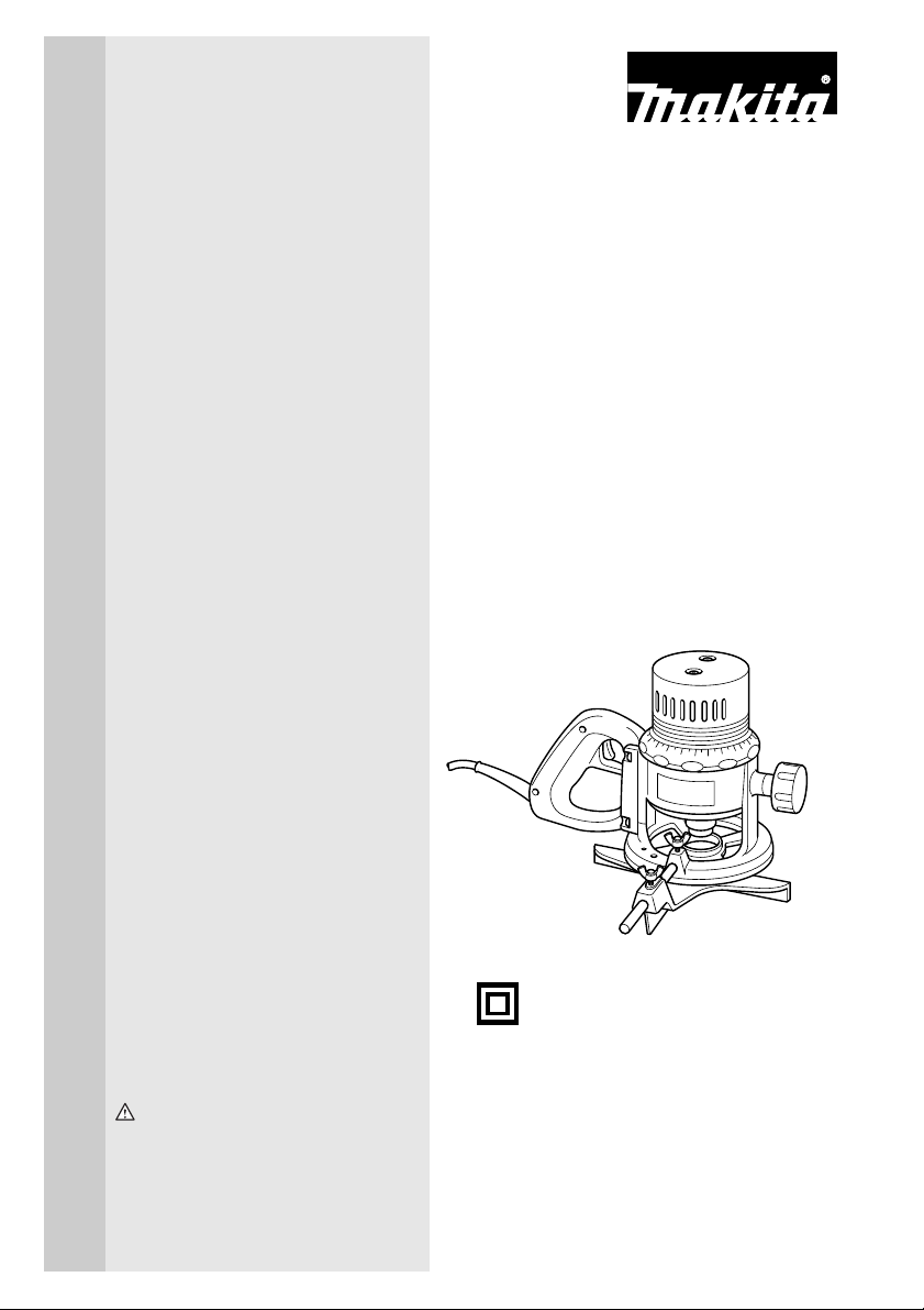
Router
MODEL 3601B
DOUBLE
INSULATION
INSTRUCTION MANUAL
WARNING:
For your personal safety, READ and UNDERSTAND before using.
SAVE THESE INSTRUCTIONS FOR FUTURE REFERENCE.
005038
Page 2
SPECIFICATIONS
Model 3601B
Collet chuck capacity 12 mm
No load speed (min-1)
Overall height 190 mm
Net weight 3.5 kg
Safety class
• Due to our continuing programme of research and development, the specifications herein are subject to change
without notice.
• Note: Specifications may differ from country to country.
SYMBOLS
The following show the symbols used for the tool. Be
sure that you understand their meaning before use.
...................Read instruction manual.
...................DOUBLE INSULATION
Intended use
The tool is intended for flush trimming and profiling of
wood, plastic and similar materials.
Power supply
The tool should be connected only to a power supply of
the same voltage as indicated on the nameplate, and
can only be operated on single-phase AC supply. They
are double-insulated in accordance with European
Standard and can, therefore, also be used from sockets
without earth wire.
END201-1
For European countries only
Noise and Vibration
The typical A-weighted noise levels are
sound pressure level: 94 dB (A)
sound power level: 105 dB (A)
Uncertainty: 3 dB(A)
– Wear ear protection. –
The typical weighted root mean square acceleration
value is not more than 2.5 m/s
These values have been obtained according to
EN60745.
EC-DECLARATION OF CONFORMITY
We declare under our sole responsibility that this product
is in compliance with the following standards of standardized documents, EN60745, EN55014, EN61000 in
accordance with Council Directives, 73/23/EEC, 89/336/
EEC, 98/37/EC.
Yasuhiko Kanzaki CE 2004
23,000
/II
2
.
MAKITA INTERNATIONAL EUROPE LTD.
Director
Michigan Drive, Tongwell, Milton Keynes, Bucks MK15
8JD, ENGLAND
Responsible manufacturer:
Makita Corporation Anjo Aichi Japan
2
Page 3

SAFETY INSTRUCTIONS ENA001-2
WARNING:
When using electric tools, basic safety precautions, including the following,
should always be followed to reduce the risk of fire, electric shock and
personal injury. Read all these instructions before operating this product
and save these instructions.
For safe operations:
1. Keep work area clean.
Cluttered areas and benches invite injuries.
2. Consider work area environment.
Do not expose power tools to rain. Do not use
power tools in damp or wet locations. Keep work
area well lit. Do not use power tools where there is
risk to cause fire or explosion.
3. Guard against electric shock.
Avoid body contact with earthed or grounded surfaces (e.g. pipes, radiators, ranges, refrigerators).
4. Keep children away.
Do not let visitors touch the tool or extension cord.
All visitors should be kept away from work area.
5. Store idle tools.
When not in use, tools should be stored in a dry,
high or locked up place, out of reach of children.
6. Do not force the tool.
It will do the job better and safer at the rate for which
it was intended.
7. Use the right tool.
Do not force small tools or attachments to do the job
of a heavy duty tool. Do not use tools for purposes
not intended; for example, do not use circular saws
to cut tree limbs or logs.
8. Dress properly.
Do not wear loose clothing or jewellery, they can be
caught in moving parts. Rubber gloves and non-skid
footwear are recommended when working outdoors.
Wear protecting hair covering to contain long hair.
9. Use safety glasses and hearing protection.
Also use face or dust mask if the cutting operation is
dusty.
10. Connect dust extraction equipment.
If devices are provided for the connection of dust
extraction and collection facilities ensure these are
connected and properly used.
11. Do not abuse the cord.
Never carry the tool by the cord or yank it to disconnect it from the socket. Keep the cord away from
heat, oil and sharp edges.
12. Secure work.
Use clamps or a vice to hold the work. It is safer
than using your hand and it frees both hands to
operate the tool.
13. Do not overreach.
Keep proper footing and balance at all times.
14. Maintain tools with care.
Keep cutting tools sharp and clean for better and
safer performance. Follow instructions for lubrica-
tion and changing accessories. Inspect tool cord
periodically and if damaged have it repaired by an
authorized service facility. Inspect extension cords
periodically and replace, if damaged. Keep handles
dry, clean and free from oil and grease.
15. Disconnect tools.
When not in use, before servicing and when changing accessories such as blades, bits and cutters.
16. Remove adjusting keys and wrenches.
Form the habit of checking to see that keys and
adjusting wrenches are removed from the tool
before turning it on.
17. Avoid unintentional starting.
Do not carry a plugged-in tool with a finger on the
switch. Ensure switch is off when plugging in.
18. Use outdoor extension leads.
When tool is used outdoors, use only extension
cords intended for outdoor use.
19. Stay alert.
Watch what you are doing. Use common sense. Do
not operate tool when you are tired.
20. Check damaged parts.
Before further use of the tool, a guard or other part
that is damaged should be carefully checked to
determine that it will operate properly and perform
its intended function. Check for alignment of moving
parts, free running of moving parts, breakage of
parts, mounting and any other conditions that may
affect its operation. A guard or other part that is
damaged should be properly repaired or replaced
by an authorized service center unless otherwise
indicated in this instruction manual. Have defective
switches replaced by an authorized service facility.
Do not use the tool if the switch does not turn it on
and off.
21. Warning.
The use of any accessory or attachment, other than
those recommended in this instruction manual or
the catalog, may present a risk of personal injury.
22. Have your tool repaired by a qualified person.
This electric tool is in accordance with the relevant
safety requirements. Repairs should only be carried
out by qualified persons using original spare parts,
otherwise this may result in considerable danger to
the user.
3
Page 4

ADDITIONAL SAFETY RULES ENB033-2
1. Hold tool by insulated gripping surfaces when
performing an operation where the cutting tool
may contact hidden wiring or its own cord. Con-
tact with a “live” wire will make exposed metal parts
of the tool “live” and shock the operator.
2. Wear hearing protection during extended period
of operation.
3. Handle the bits very carefully.
4. Check the bit carefully for cracks or damage
before operation. Replace cracked or damaged
bit immediately.
5. Avoid cutting nails. Inspect for and remove all
nails from the workpiece before operation.
6. Hold the tool firmly with both hands.
7. Keep hands away from rotating parts.
8. Make sure the bit is not contacting the work-
piece before the switch is turned on.
9. Before using the tool on an actual workpiece, let
it run for a while. Watch for vibration or wobbling that could indicate improperly installed bit.
10. Be careful of the bit rotating direction and the
feed direction.
11. Do not leave the tool running. Operate the tool
only when hand-held.
12. Always switch off and wait for the bit to come to
a complete stop before removing the tool from
workpiece.
13. Do not touch the bit immediately after operation;
it may be extremely hot and could burn your
skin.
14. Always lead the power supply cord away from
the tool towards the rear.
15. Do not smear the tool base carelessly with thinner, gasoline, oil or the like. They may cause
cracks in the tool base.
16. Draw attention to the need to use cutters of the
correct shank diameter and which are suitable
for the speed of the tool.
SAVE THESE INSTRUCTIONS
4
Page 5

FUNCTIONAL
DESCRIPTION
CAUTION:
• Always be sure that the tool is switched off and unplugged before
adjusting or checking function on the tool.
005039
Adjusting the depth of cut
Place the tool on a flat surface. Turn the scale ring until it makes contact with
1
the base. Loosen the knob. Turn the scale ring until the bit just touches the flat
surface. Tighten the knob. Place the tool on its side and turn the scale ring
counterclockwise (when viewing the tool from the top) until the desired depth
of cut is obtained. One full turn of the scale ring is equal to 5 mm change in
depth setting. Loosen the knob and move the tool base until it makes contact
with the scale ring. Then tighten the knob securely.
2
1. Scale ring
2. Knob
1. Lock button
2. Switch trigger
1. Switch trigger
CAUTION:
• Since excessive cutting may cause overload of the motor or difficulty in
controlling the tool, the depth of cut should not be more than 15 mm at a
pass when cutting grooves. When you wish to cut grooves more than
15 mm deep, make several passes with progressively deeper bit settings.
005040
Switch action
1
2
005041
1
CAUTION:
• Before plugging in the tool, always check to see that the switch trigger
actuates properly and returns to the “OFF” position when released.
For tool with lock button
To start the tool, simply pull the switch trigger. Release the switch trigger to
stop.
For continuous operation, pull the switch trigger and then push in the lock button.
To stop the tool from the locked position, pull the switch trigger fully, then
release it.
For tool without lock button
To start the tool, simply pull the switch trigger. Release the switch trigger to
stop.
5
Page 6

ASSEMBLY
OPERATION
CAUTION:
• Always be sure that the tool is switched off and unplugged before
carrying out any work on the tool.
005042
Installing or removing the bit
CAUTION:
• Install the bit securely. Always use only the wrenches provided with the
tool. A loose or overtightened bit can be dangerous.
• Do not tighten the collet chuck without inserting a bit or install smaller
shank bits without using a collet sleeve. Either can lead to breakage of
the collet chuck.
Insert the bit all the way into the collet chuck and withdraw it very slightly
(approx. 2 mm). Then tighten the collet chuck securely with the two wrenches.
When using smaller shank bits, first insert the appropriate collet sleeve into the
collet chuck, then install the bit as mentioned above.
To remove the bit, follow the installation procedure in reverse.
Set the tool base on the workpiece to be cut without the bit making any contact. Then turn the tool on and wait until the bit attains full speed. Move the tool
forward over the workpiece surface, keeping the tool base flush and advancing
smoothly until the cutting is complete.
When doing edge cutting, the workpiece surface should be on the left side of
the bit in the feed direction.
001984
2
1
2
4
3
4
2
1
1. Feed direction
2. Bit revolving direction
3. Workpiece
4. Straight guide
6
001985
4
1. Workpiece 2. Bit revolving direction
3. View from the top of the tool 4. Feed direction
NOTE:
3
• Moving the tool forward too fast may cause a poor quality of cut, or
damage to the bit or motor. Moving the tool forward too slowly may burn
and mar the cut. The proper feed rate will depend on the bit size, the kind
of workpiece and depth of cut. Before beginning the cut on the actual
workpiece, it is advisable to make a sample cut on a piece of scrap
lumber. This will show exactly how the cut will look as well as enable you
to check dimensions.
• When using the straight guide or the trimmer guide, be sure to install it
on the right side in the feed direction. This will help to keep it flush with
the side of the workpiece.
Page 7

12
3
1. Wing bolt (B)
2. Wing bolt (A)
3. Straight guide
4. Guide bar
005043
Straight guide
The straight guide is effectively used for straight cuts when chamfering or
grooving.
To install the straight guide, insert the guide bar into the holes in the tool base
005044
until the notch in the guide bar reaches just under the wing bolt (B). Then
tighten wing bolt (B). Loosen the wing bolt (A) and adjust the distance between
4
the bit and the straight guide. At the desired distance, tighten the wing bolt (A)
to secure the straight guide in place.
When cutting, move the tool with the straight guide flush with the side of the
workpiece.
005045
Templet guide (Accessory)
The templet guide provides a sleeve through which the bit passes, allowing
use of the tool with templet patterns.
1
1. Base plate
2. Templet guide
005046
To install the templet guide, screw the templet guide on the base plate.
2
7
Page 8

1
003695
7
2
3
4
5
6
1. Bit
2. Base
3. Templet
4. Workpiece
5. Distance (X)
6. Outside diameter of the templet
guide
7. Templet guide
005047
005048
1
2
Secure the templet to the workpiece. Place the tool on the templet and move
the tool with the templet guide sliding along the side of the templet.
NOTE:
• The workpiece will be cut a slightly different size from the templet. Allow
for the distance (X) between the bit and the outside of the templet guide.
The distance (X) can be calculated by using the following equation:
Distance (X) = (outside diameter of the templet guide - bit diameter) / 2
Trimmer guide (Accessory)
Trimming, curved cuts in veneers for furniture and the like can be done easily
with the trimmer guide. The guide roller rides the curve and assures a fine cut.
Install the trimmer guide on the tool base with the wing bolts (B). Loosen the
wing bolt (A) and adjust the distance between the bit and the trimmer guide by
turning the fine adjusting screw (1.5 mm per turn). At the desired distance,
tighten the wing bolt (A) to secure the trimmer guide in place. When adjusting
the guide roller up or down, loosen the wing bolt (C). After adjusting it, tighten
the wing bolt (C) securely.
3
4
1. Wing bolt (B)
2. Fine adjusting screw
3. Wing bolt (A)
4. Trimmer guide
5. Wing bolt (C)
6. Guide roller
8
6
5
Page 9

3
1. Bit
2. Guide roller
3. Workpiece
1. Vacuum hose
2. Vacuum cleaner
1
2
3
When cutting, move the tool with the guide roller riding the side of the work-
003701
1
piece.
2
006286
Connecting a vacuum cleaner
1
Connect a vacuum hose to the tool and further connect another end of it to the
vacuum cleaner. Secure the hose to the router base with a screw in the figure.
2
006287
4
1. Screwdriver
2. Screw
3. Hole
4. Vacuum hose
5. Router base
5
9
Page 10

123
54
1. Hose
2. Joint
3. Vacuum hose
4. Outer diameter ø32 mm
5. Inner diameter ø38 mm
Connect another and of the hose to the vacuum cleaner hose of 38 mm in
006288
inner diameter using a joint.
MAINTENANCE
1. Limit mark
1. Screwdriver
2. Rear cover
CAUTION:
• Always be sure that the tool is switched off and unplugged before
attempting to perform inspection or maintenance.
001145
Replacing carbon brushes
Remove and check the carbon brushes regularly. Replace when they wear
down to the limit mark. Keep the carbon brushes clean and free to slip in the
holders. Both carbon brushes should be replaced at the same time. Use only
identical carbon brushes.
1
005049
Use a screwdriver to remove the rear cover.
1
2
10
Page 11

Use a screwdriver to remove the brush holder caps. Take out the worn carbon
005050
brushes, insert the new ones and secure the brush holder caps.
1
2
1. Brush holder cap
2. Screwdriver
Then install the rear cover with the screws.
CAUTION:
• Do not turn the tool on without the rear cover installed in place.
To maintain product SAFETY and RELIABILITY, repairs, any other maintenance or adjustment should be performed by Makita Authorized Service Centers, always using Makita replacement parts.
ACCESSORIES
CAUTION:
• These accessories or attachments are recommended for use with your Makita tool specified in this manual. The
use of any other accessories or attachments might present a risk of injury to persons. Only use accessory or
attachment for its stated purpose.
If you need any assistance for more details regarding these accessories, ask your local Makita service center.
• Straight & groove forming bits
• Edge forming bits
• Laminate trimming bits
• Straight guide assembly
• Trimmer guide assembly
• Templet guide 25
• Templet guides
• Templet guide adapter
• Lock nut
• Collet cone 12 mm, 1/2”
• Collet sleeve 3/8”, 1/4”
• Collet sleeve 6 mm, 8 mm, 10 mm
• Wrench 21
• Wrench 23
11
Page 12

883011A224
Makita Corporation Anjo, Aichi, Japan
 Loading...