

Page 1
INSTRUCTION MANUAL
MANUEL D'INSTRUCTION
MANUAL DE INSTRUCCIONES
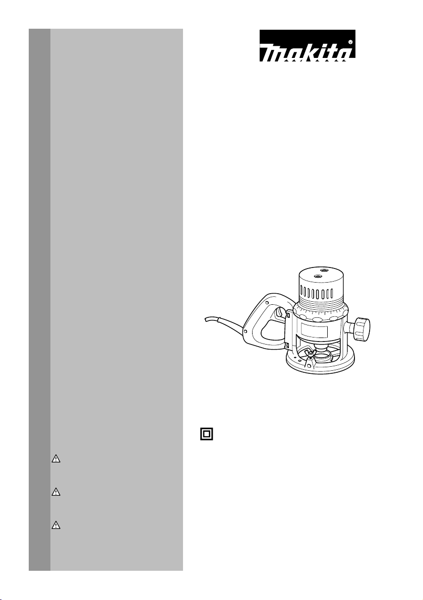
Router
Défonceuse
Rebajadora
3601B
005038
DOUBLE INSULATION
DOUBLE ISOLATION
WARNING:
For your personal safety, READ and UNDERSTAND before using.
SAVE THESE INSTRUCTIONS FOR FUTURE REFERENCE.
AVERTISSEMENT:
Pour votre propre sécurité, prière de lire attentivement avant l'utilisation.
GARDER CES INSTRUCTIONS POUR RÉFÉRENCE ULTÉRIEURE.
ADVERTENCIA:
Para su seguridad personal, LEA DETENIDAMENTE este manual antes de usar la
herramienta.
GUARDE ESTAS INSTRUCCIONES PARA FUTURA REFERENCIA.
DOBLE AISLAMIENTO
1
Page 2

ENGLISH
SPECIFICATIONS
Model 3601B
Collet chuck capacity 12 mm (1/2")
No load speed (RPM) 23000/min.
Overall height 190 mm (7-1/2")
• Due to our continuing programme of research and development, the specifications herein are subject to change without notice.
• Specifications may differ from country to country.
• Weight according to EPTA-Procedure 01/2003
GENERAL SAFETY RULES
WARNING! Read all instructions. Failure to follow all
instructions listed below may result in electric shock, fire
and/or serious injury. The term "power tool" in all of the
warnings listed below refers to your mains-operated
(corded) power tool or battery-operated (cordless) power
tool.
SAVE THESE INSTRUCTIONS.
Work area safety
1. Keep work area clean and well lit. Cluttered and
dark areas invite accidents.
2. Do not operate power tools in explosive
atmospheres, such as in the presence of
flammable liquids, gases or dust. Power tools
create sparks which may ignite the dust or fumes.
3. Keep children and bystanders away while
operating a power tool. Distractions can cause
you to lose control.
Electrical Safety
4. Power tool plugs must match the outlet. Never
modify the plug in any way. Do not use any
adapter plugs with earthed (grounded) power
tools. Unmodified plugs and matching outlets will
reduce risk of electric shock.
5. Avoid body contact with earthed or grounded
surfaces such as pipes, radiators, ranges and
refrigerators. There is an increased risk of
electric shock if your body is earthed or grounded.
6. Do not expose power tools to rain or wet
conditions. Water entering a power tool will
increase the risk of electric shock.
7. Do not abuse the cord. Never use the cord for
carrying, pulling or unplugging the power tool.
Keep cord away from heat, oil, sharp edges or
moving parts. Damaged or entangled cords
increase the risk of electric shock.
8. When operating a power tool outdoors, use an
extension cord suitable for outdoor use. Use of
a cord suitable for outdoor use reduces the risk of
Net weight 3.6 kg (7.9 lbs)
GEA001-3
electric shock.
Personal Safety
9. Stay alert, watch what you are doing and use
common sense when operating a power tool.
Do not use a power tool while you are tired or
under the influence of drugs, alcohol or
medication. A moment of inattention while
operating power tools may result in serious
personal injury.
10. Use safety equipment. Always wear eye
protection. Safety equipment such as dust mask,
non-skid safety shoes, hard hat, or hearing
protection used for appropriate conditions will
reduce personal injuries.
11. Avoid accidental starting. Ensure the switch is
in the off-position before plugging in. Carrying
power tools with your finger on the switch or
plugging in power tools that have the switch on
invites accidents.
12. Remove any adjusting key or wrench before
turning the power tool on. A wrench or a key left
attached to a rotating part of the power tool may
result in personal injury.
13. Do not overreach. Keep proper footing and
balance at all times. This enables better control
of the power tool in unexpected situations.
14. Dress properly. Do not wear loose clothing or
jewellery. Keep your hair, clothing, and gloves
away from moving parts. Loose clothes,
jewellery or long hair can be caught in moving
parts.
15. If devices are provided for the connection of
dust extraction and collection facilities,
ensure these are connected and properly used.
Use of these devices can reduce dust-related
hazards.
Power tool use and care
16. Do not force the power tool. Use the correct
power tool for your application. The correct
power tool will do the job better and safer at the
rate for which it was designed.
2
Page 3

17. Do not use the power tool if the switch does
not turn it on and off. Any power tool that cannot
be controlled with the switch is dangerous and
must be repaired.
18. Disconnect the plug from the power source
and/or the battery pack from the power tool
before making any adjustments, changing
accessories, or storing power tools. Such
preventive safety measures reduce the risk of
starting the power tool accidentally.
19. Store idle power tools out of the reach of
children and do not allow persons unfamiliar
with the power tool or these instructions to
operate the power tool. Power tools are
dangerous in the hands of untrained users.
20. Maintain power tools. Check for misalignment
or binding of moving parts, breakage of parts
and any other condition that may affect the
power tools operation. If damaged, have the
power tool repaired before use. Many accidents
are caused by poorly maintained power tools.
21. Keep cutting tools sharp and clean. Properly
maintained cutting tools with sharp cutting edges
are less likely to bind and are easier to control.
22. Use the power tool, accessories and tool bits
etc. in accordance with these instructions and
in the manner intended for the particular type
of power tool, taking into account the working
conditions and the work to be performed. Use
of the power tool for operations different from
those intended could result in a hazardous
situation.
Service
23. Have your power tool serviced by a qualified
repair person using only identical replacement
parts. This will ensure that the safety of the power
tool is maintained.
24. Follow instruction for lubricating and
changing accessories.
25. Keep handles dry, clean and free from oil and
grease.
GEB018-1
SPECIFIC SAFETY RULES
DO NOT let comfort or familiarity with product
(gained from repeated use) replace strict adherence
to router safety rules. If you use this tool unsafely or
incorrectly, you can suffer serious personal injury.
1. Hold power tools by insulated gripping
surfaces when performing an operation where
the cutting tool may contact hidden wiring or
its own cord. Contact with a "live" wire will make
exposed metal parts of the tool "live" and shock
the operator.
2. Use clamps or another practical way to secure
and support the workpiece to a stable platform.
Holding the work by hand or against your body
leaves it unstable and may lead to loss of control.
3. Wear hearing protection during extended
period of operation.
4. Handle the bits very carefully.
5. Check the bit carefully for cracks or damage
before operation. Replace cracked or
damaged bit immediately.
6. Avoid cutting nails. Inspect for and remove all
nails from the workpiece before operation.
7. Hold the tool firmly with both hands.
8. Keep hands away from rotating parts.
9. Make sure the bit is not contacting the
workpiece before the switch is turned on.
10. Before using the tool on an actual workpiece,
let it run for a while. Watch for vibration or
wobbling that could indicate improperly
installed bit.
11. Be careful of the bit rotating direction and the
feed direction.
12. Do not leave the tool running. Operate the tool
only when hand-held.
13. Always switch off and wait for the bit to come
to a complete stop before removing the tool
from workpiece.
14. Do not touch the bit immediately after
operation; it may be extremely hot and could
burn your skin.
15. Do not smear the tool base carelessly with
thinner, gasoline, oil or the like. They may
cause cracks in the tool base.
16. Draw attention to the need to use cutters of the
correct shank diameter and which are suitable
for the speed of the tool.
17. Some material contains chemicals which may
be toxic. Take caution to prevent dust
inhalation and skin contact. Follow material
supplier safety data.
18. Always use the correct dust mask/respirator
for the material and application you are
working with.
SAVE THESE INSTRUCTIONS.
WARNING:
MISUSE or failure to follow the safety rules stated in
this instruction manual may cause serious personal
injury.
3
Page 4
USD201-2
Symbols
The followings show the symbols used for tool.
・ volts
・ amperes
・ hertz
・ alternating current
・ no load speed
・ Class II Construction
・ revolutions or reciprocation per minute
FUNCTIONAL DESCRIPTION
CAUTION:
• Always be sure that the tool is switched off and
unplugged before adjusting or checking function on
the tool.
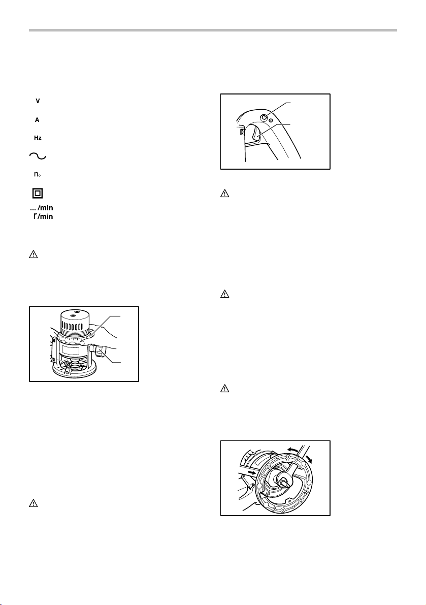
Adjusting the depth of cut
1. Scale ring
1
2. Knob
2
005039
Place the tool on a flat surface. Turn the scale ring until it
makes contact with the base. Loosen the knob. Turn the
scale ring until the bit just touches the flat surface.
Tighten the knob. Place the tool on its side and turn the
scale ring counterclockwise (when viewing the tool from
the top) until the desired depth of cut is obtained. One
full turn of the scale ring is equal to 5 mm (about 3/16")
change in depth setting. Loosen the knob and move the
tool base until it makes contact with the scale ring. Then
tighten the knob securely.
CAUTION:
• Since excessive cutting may cause overload of the
motor or difficulty in controlling the tool, the depth
of cut should not be more than 15 mm (5/8") at a
pass when cutting grooves. When you wish to cut
grooves more than 15 mm (5/8") deep, make
several passes with progressively deeper bit
settings.
Switch action
1
2
005040
CAUTION:
• Before plugging in the tool, always check to see
that the switch trigger actuates properly and
returns to the "OFF" position when released.
To start the tool, simply pull the switch trigger. Release
the switch trigger to stop.
For continuous operation, pull the switch trigger and
then push in the lock button.
To stop the tool from the locked position, pull the switch
trigger fully, then release it.
CAUTION:
• Switch can be locked in "ON" position for ease of
operator comfort during extended use. Apply
caution when locking tool in "ON" position and
maintain firm grasp on tool.
• Hold the tool firmly when turning off the tool, to
overcome the reaction.
1. Lock button
2. Switch trigger
ASSEMBLY
CAUTION:
• Always be sure that the tool is switched off and
unplugged before carrying out any work on the
tool.
Installing or removing the bit
005042
4
Page 5
CAUTION:
• Install the bit securely. Always use only the
wrenches provided with the tool. A loose or
overtightened bit can be dangerous.
• Do not tighten the collet chuck without inserting a
bit or install smaller shank bits without using a
collet sleeve. Either can lead to breakage of the
collet chuck.
Insert the bit all the way into the collet chuck and
withdraw it very slightly (approx. 2 mm). Then tighten the
collet chuck securely with the two wrenches. When
using smaller shank bits, first insert the appropriate
collet sleeve into the collet chuck, then install the bit as
mentioned above.
To remove the bit, follow the installation procedure in
reverse.
OPERATION
the bit size, the kind of workpiece and depth of cut.
Before beginning the cut on the actual workpiece, it
is advisable to make a sample cut on a piece of
scrap lumber. This will show exactly how the cut
will look as well as enable you to check
dimensions.
• When using the straight guide or the trimmer guide,
be sure to install it on the right side in the feed
direction. This will help to keep it flush with the side
of the workpiece.
2
1
001985
1. Feed direction
3
2. Bit revolving
direction
3. Workpiece
4. Straight guide
4
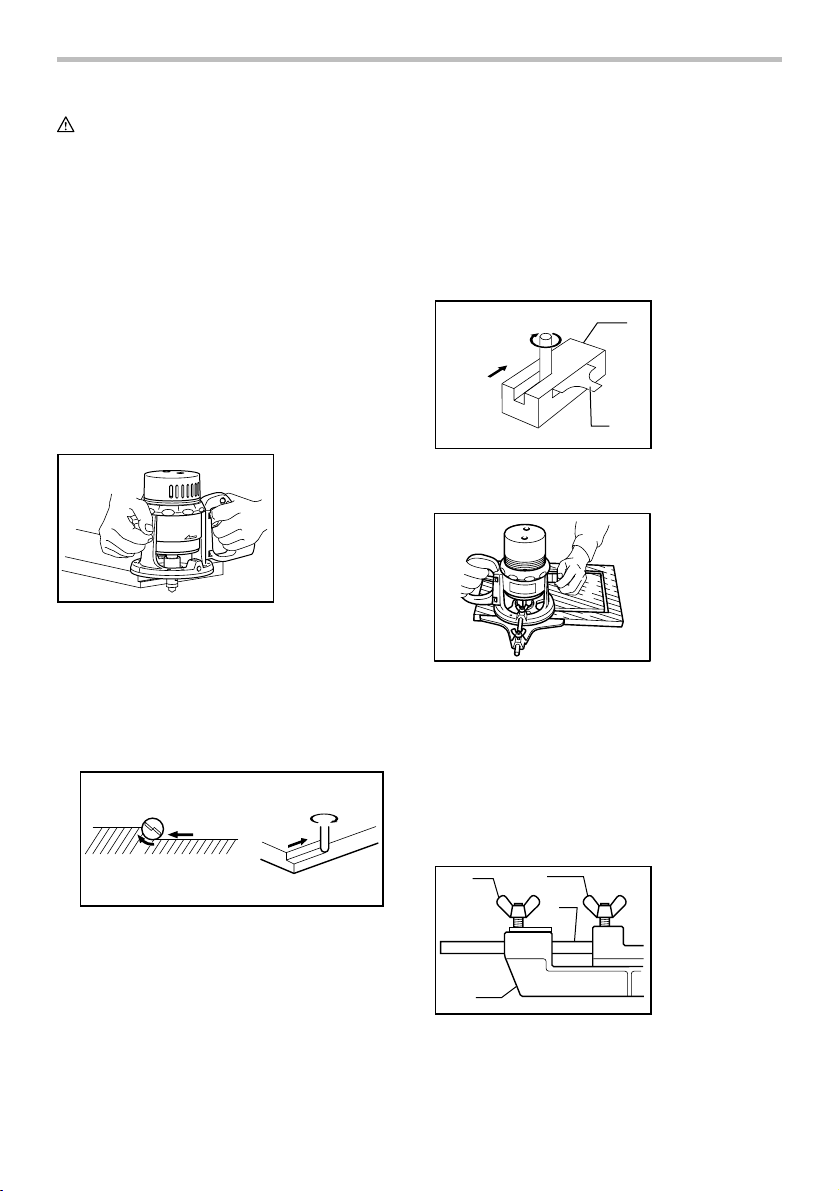
Straight guide (optional accessory)
007438
Set the tool base on the workpiece to be cut without the
bit making any contact. Then turn the tool on and wait
until the bit attains full speed. Move the tool forward over
the workpiece surface, keeping the tool base flush and
advancing smoothly until the cutting is complete.
When doing edge cutting, the workpiece surface should
be on the left side of the bit in the feed direction.
1
2
1. Workpiece
2. Bit revolving direction
3. View from the top of the tool
4. Feed direction
001984
NOTE:
• Moving the tool forward too fast may cause a poor
quality of cut, or damage to the bit or motor.
Moving the tool forward too slowly may burn and
mar the cut. The proper feed rate will depend on
4
3
2
4
005043
The straight guide is effectively used for straight cuts
when chamfering or grooving.
To install the straight guide, insert the guide bar into the
holes in the tool base until the notch in the guide bar
reaches just under the wing bolt (B). Then tighten wing
bolt (B). Loosen the wing bolt (A) and adjust the distance
between the bit and the straight guide. At the desired
distance, tighten the wing bolt (A) to secure the straight
guide in place.
12
4
1. Wing bolt (B)
2. Wing bolt (A)
3. Straight guide
4. Guide bar
3
005044
When cutting, move the tool with the straight guide flush
with the side of the workpiece.
5
Page 6
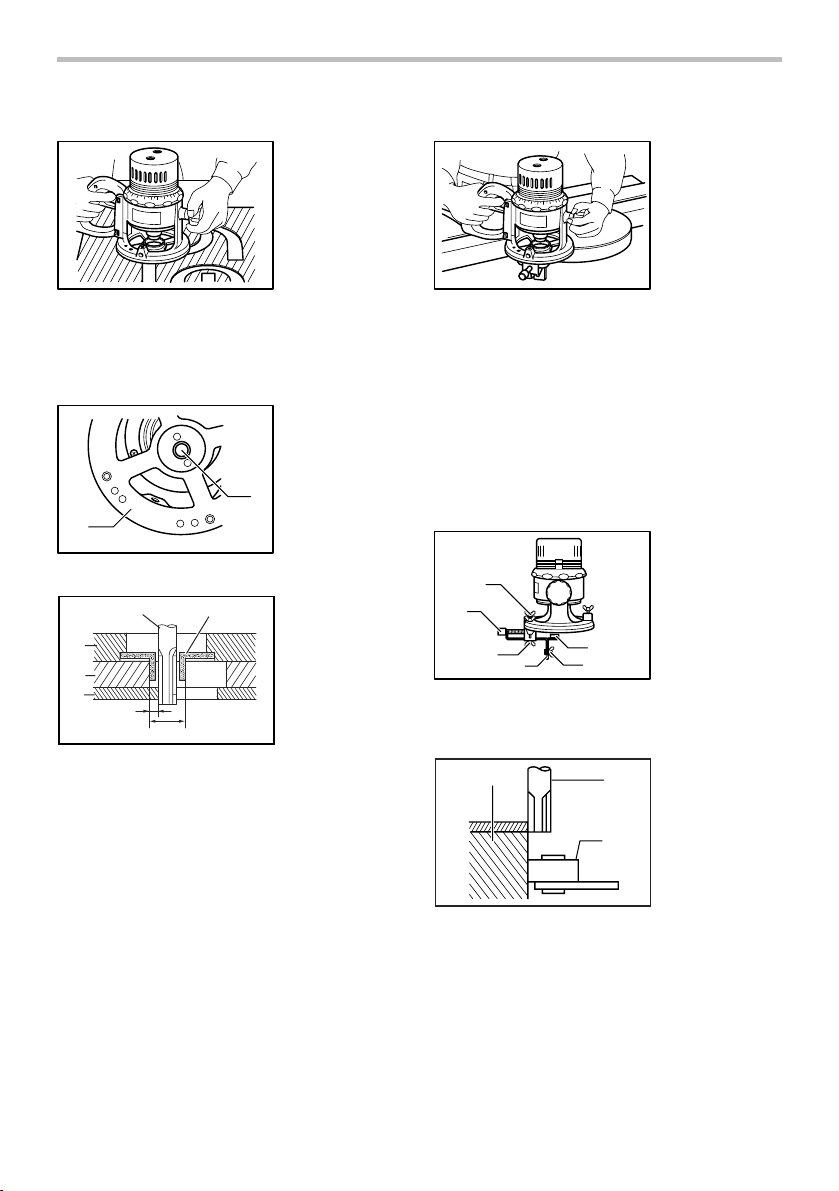
Templet guide (optional accessory)
Trimmer guide (optional accessory)
005045
The templet guide provides a sleeve through which the
bit passes, allowing use of the tool with templet patterns.
To install the templet guide, screw the templet guide on
the base plate.
1
005046
1
2
3
4
5
003695
NOTE:
• The workpiece will be cut a slightly different size
from the templet. Allow for the distance (X)
between the bit and the outside of the templet
guide. The distance (X) can be calculated by using
the following equation:
Distance (X) = (outside diameter of the templet
guide - bit diameter) / 2
7
6
1. Base plate
2. Templet guide
2
1. Bit
2. Base
3. Templet
4. Workpiece
5. Distance (X)
6. Outside
diameter of the
templet guide
7. Templet guide
005047
Trimming, curved cuts in veneers for furniture and the
like can be done easily with the trimmer guide. The
guide roller rides the curve and assures a fine cut.
Install the trimmer guide on the tool base with the wing
bolts (B). Loosen the wing bolt (A) and adjust the
distance between the bit and the trimmer guide by
turning the fine adjusting screw (1.5 mm or about 1/16"
per turn). At the desired distance, tighten the wing bolt
(A) to secure the trimmer guide in place. When adjusting
the guide roller up or down, loosen the wing bolt (C).
After adjusting it, tighten the wing bolt (C) securely.
1
2
3
4
005048
When cutting, move the tool with the guide roller riding
the side of the workpiece.
3
003701
5
1. Wing bolt (B)
2. Fine adjusting
screw
3. Wing bolt (A)
4. Trimmer guide
5. Wing bolt (C)
6
6. Guide roller
1. Bit
1
2. Guide roller
3. Workpiece
2
6
Page 7
MAINTENANCE
CAUTION:
• Always be sure that the tool is switched off and
unplugged before attempting to perform inspection
or maintenance.
• Never use gasoline, benzine, thinner, alcohol or
the like. Discoloration, deformation or cracks may
result.
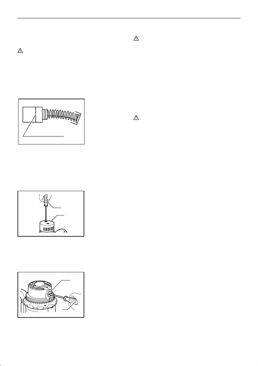
Replacing carbon brushes
1. Limit mark
1
001145
Remove and check the carbon brushes regularly.
Replace when they wear down to the limit mark. Keep
the carbon brushes clean and free to slip in the holders.
Both carbon brushes should be replaced at the same
time. Use only identical carbon brushes.
Use a screwdriver to remove the rear cover.
1
2
005049
Use a screwdriver to remove the brush holder caps.
Take out the worn carbon brushes, insert the new ones
and secure the brush holder caps.
Then install the rear cover with the screws.
1. Screwdriver
2. Rear cover
1. Brush holder
1
cap
2. Screwdriver
CAUTION:
• Do not turn the tool on without the rear cover
installed in place.
To maintain product SAFETY and RELIABILITY, repairs,
any other maintenance or adjustment should be
performed by Makita Authorized Service Centers,
always using Makita replacement parts.
To maintain product SAFETY and RELIABILITY, repairs,
any other maintenance or adjustment should be
performed by Makita Authorized or Factory Service
Centers, always using Makita replacement parts.
ACCESSORIES
CAUTION:
• These accessories or attachments are
recommended for use with your Makita tool
specified in this manual. The use of any other
accessories or attachments might present a risk of
injury to persons. Only use accessory or
attachment for its stated purpose.
If you need any assistance for more details regarding
these accessories, ask your local Makita Service Center.
• Straight & groove forming bits
• Edge forming bits
• Laminate trimming bits
• Straight guide
• Trimmer guide
• Templet guide 25
• Templet guides
• Templet guide adapter
• Lock nut
• Collet sleeve 3/8", 1/4"
• Wrench 21
• Wrench 23
• Router stand
005050
2
7
Page 8

MAKITA LIMITED ONE YEAR WARRANTY
Warranty Policy
Every Makita tool is thoroughly inspected and tested
before leaving the factory. It is warranted to be free of
defects from workmanship and materials for the period
of ONE YEAR from the date of original purchase.
Should any trouble develop during this one year period,
return the COMPLETE tool, freight prepaid, to one of
Makita’s Factory or Authorized Service Centers. If
inspection shows the trouble is caused by defective
workmanship or material, Makita will repair (or at our
option, replace) without charge.
This Warranty does not apply where:
repairs have been made or attempted by others:
repairs are required because of normal wear and
tear:
the tool has been abused, misused or improperly
maintained:
alterations have been made to the tool.
IN NO EVENT SHALL MAKITA BE LIABLE FOR ANY
INDIRECT, INCIDENTAL OR CONSEQUENTIAL
DAMAGES FROM THE SALE OR USE OF THE
PRODUCT. THIS DISCLAIMER APPLIES BOTH
DURING AND AFTER THE TERM OF THIS
WARRANTY.
MAKITA DISCLAIMS LIABILITY FOR ANY IMPLIED
WARRANTIES, INCLUDING IMPLIED WARRANTIES
OF "MERCHANTABILITY" AND "FITNESS FOR A
SPECIFIC PURPOSE," AFTER THE ONE YEAR TERM
OF THIS WARRANTY.
This Warranty gives you specific legal rights, and you
may also have other rights which vary from state to
state. Some states do not allow the exclusion or
limitation of incidental or consequential damages, so
the above limitation or exclusion may not apply to you.
Some states do not allow limitation on how long an
implied warranty lasts, so the above limitation may not
apply to you.
EN0006-1
8
Page 9

FRANÇAIS
SPÉCIFICATIONS
Modèle 3601B
Capacité du mandrin à bague 12 mm (1/2")
Vitesse à vide (T/MIN) 23 000/min.
Hauteur hors tout 190 mm (7-1/2")
Poids net 3,6 kg (7,9 lbs)
• Étant donné l'évolution constante de notre programme de recherche et de développement, les spécifications contenues dans ce
manuel sont sujettes à modification sans préavis.
• Les spécifications peuvent varier suivant les pays.
• Poids conforme à la procédure EPTA du 01/2003
Règles de sécurité générales
AVERTISSEMENT! Veuillez lire l'ensemble des
présentes instructions. Il y a risque de choc électrique,
d'incendie et/ou de blessure grave si toutes les
instructions énumérées ci-dessous ne sont pas
respectées. Le terme ≪outil électrique≫ qui figure sur
tous les avertissements énumérés ci-dessous fait
référence à un outil électrique branché sur une prise de
courant (par un cordon d'alimentation) ou alimenté par
batterie (sans fil).
CONSERVEZ CE MODE
D'EMPLOI.
Sécurité de la zone de travail
1. Maintenez la zone de travail propre et bien
éclairée. Les zones de travail encombrées et
sombres ouvrent grande la porte aux accidents.
2. N'utilisez pas les outils électriques dans les
atmosphères explosives, par exemple en
présence de liquides, gaz ou poussières
inflammables. Les outils électriques produisent
des étincelles au contact desquelles la poussière
ou les vapeurs peuvent s'enflammer.
3. Assurez-vous qu'aucun enfant ou curieux ne
s'approche pendant que vous utilisez un outil
électrique. Vous risquez de perdre la maîtrise de
l'outil si votre attention est détournée.
Sécurité en matière d'électricité
4. Les fiches d'outil électrique sont conçues
pour s'adapter parfaitement aux prises de
courant. Ne modifiez jamais la fiche de
quelque façon que ce soit. N'utilisez aucun
adaptateur de fiche sur les outils électriques
avec mise à la terre. En ne modifiant pas les
fiches et en les insérant dans des prises de
courant pour lesquelles elles ont été conçues
vous réduirez les risques de choc électrique.
5. Évitez tout contact corporel avec les surfaces
mises à la terre, telles que les tuyaux,
GEA001-3
radiateurs, cuisinières et réfrigérateurs. Le
risque de choc électrique est plus élevé si votre
corps se trouve mis à la terre.
6. N'exposez pas les outils électriques à la pluie
ou à l'eau. La présence d'eau dans un outil
électrique augmente le risque de choc électrique.
7. Ne maltraitez pas le cordon. N'utilisez jamais
le cordon pour transporter, tirer ou débrancher
l'outil électrique. Maintenez le cordon à l'écart
des sources de chaleur, de l'huile, des objets à
bords tranchants et des pièces en mouvement.
Le risque de choc électrique est plus élevé
lorsque les cordons sont endommagés ou
enchevêtrés.
8. Lorsque vous utilisez un outil électrique à
l'extérieur, utilisez un cordon prolongateur
prévu à cette fin. Les risques de choc électrique
sont moindres lorsqu'un cordon conçu pour
l'extérieur est utilisé.
Sécurité personnelle
9. Restez alerte, attentif à vos mouvements et
faites preuve de bon sens lorsque vous
utilisez un outil électrique. Évitez d'utiliser un
outil électrique si vous êtes fatigué ou si vous
avez pris une drogue, de l'alcool ou un
médicament. Un moment d'inattention pendant
l'utilisation d'un outil électrique peut entraîner une
grave blessure.
10. Utilisez des dispositifs de sécurité. Portez
toujours un protecteur pour la vue. Les risques
de blessure seront moins élevés si vous utilisez
des dispositifs de sécurité tels qu'un masque
antipoussières, des chaussures à semelle
antidérapante, une coiffure résistante ou une
protection d'oreilles.
11. Prévenez tout démarrage accidentel.
Assurez-vous que l'interrupteur est en
position d'arrêt avant de brancher l'outil. Vous
ouvrez la porte aux accidents si vous transportez
les outils électriques avec le doigt sur
l'interrupteur ou les branchez alors que
9
Page 10

l'interrupteur est en position de marche.
12. Retirez toute clé de réglage ou de serrage
avant de mettre l'outil sous tension. Toute clé
laissée en place sur une pièce rotative de l'outil
électrique peut entraîner une blessure.
13. Maintenez une bonne position. Assurez-vous
d'une bonne prise au sol et d'une bonne
position d'équilibre en tout temps. Cela vous
permettra d'avoir une meilleure maîtrise de l'outil
dans les situations imprévues.
14. Portez des vêtements adéquats. Ne portez ni
vêtements amples ni bijoux. Vous devez
maintenir cheveux, vêtements et gants à
l'écart des pièces en mouvement. Les pièces
en mouvement peuvent happer les vêtements
amples, les bijoux et les cheveux longs.
15. Si des accessoires sont fournis pour
raccorder un appareil d'aspiration et de
collecte de la poussière, assurez-vous qu'ils
sont correctement raccordés et qu'ils sont
utilisés de manière adéquate. L'utilisation de
tels accessoires permet de réduire les risques liés
à la présence de poussière dans l'air.
Utilisation et entretien des outils électriques
16. Ne forcez pas l'outil électrique. Utilisez l'outil
électrique adéquat suivant le type de travail à
effectuer. Si vous utilisez l'outil électrique
adéquat et respectez le régime pour lequel il a été
conçu, il effectuera un travail de meilleure qualité
et de façon plus sécuritaire.
17. N'utilisez pas l'outil électrique s'il n'est pas
possible de mettre sa gâchette en position de
marche et d'arrêt. Un outil électrique dont
l'interrupteur est défectueux représente un danger
et doit être réparé.
18. Débranchez la fiche de la source
d'alimentation et/ou retirez le bloc-piles de
l'outil électrique avant d'effectuer tout réglage,
de changer un accessoire ou de ranger l'outil
électrique. De telles mesures préventives
réduisent les risques de démarrage accidentel de
l'outil électrique.
19. Après l'utilisation d'un outil électrique,
rangez-le hors de portée des enfants et ne
laissez aucune personne l'utiliser si elle n'est
pas familiarisée avec l'outil électrique ou les
présentes instructions d'utilisation. Les outils
électriques représentent un danger entre les
mains de personnes qui n'en connaissent pas le
mode d'utilisation.
20. Veillez à l'entretien des outils électriques.
Assurez-vous que les pièces mobiles ne sont
pas désalignées ou coincées, qu'aucune pièce
n'est cassée et que l'outil électrique n'a subi
aucun dommage affectant son bon
fonctionnement. Le cas échéant, faites réparer
l'outil électrique avant de l'utiliser. De
nombreux accidents sont causés par des outils
électriques mal entretenus.
21. Maintenez les outils tranchants bien aiguisés
et propres. Un outil tranchant dont l'entretien est
effectué correctement et dont les bords sont bien
aiguisés risquera moins de se coincer et sera plus
facile à maîtriser.
22. Utilisez l'outil électrique, ses accessoires, ses
embouts, etc., en respectant les présentes
instructions et de la façon prévue pour ce type
particulier d'outil électrique, en tenant compte
des conditions de travail et du type de travail à
effectuer. L'utilisation d'un outil électrique à des
fins autres que celles prévues peut entraîner une
situation dangereuse.
Service
23. Faites réparer votre outil électrique par un
réparateur qualifié qui utilise des pièces de
rechange identiques aux pièces d'origine. Le
maintien de la sûreté de l'outil électrique sera
ainsi assuré.
24. Suivez les instructions de lubrification et de
changement des accessoires.
25. Maintenez les poignées de l'outil sèches,
propres et exemptes d'huile ou de graisse.
GEB018-1
RÈGLES DE SÉCURITÉ
PARTICULIÈRES
NE vous laissez PAS tromper (au fil d’une utilisation
répétée) par un sentiment d’aisance et de familiarité
avec le produit, au point de négliger le respect
rigoureux des consignes de sécurité qui
accompagnent la défonceuse. L’utilisation de cet
outil de façon non sécuritaire ou incorrecte
comporte un risque de blessure grave.
1. Tenez l'outil électrique par ses surfaces de
prise isolées pendant toute opération où l'outil
de coupe pourrait venir en contact avec un
câblage dissimulé ou avec son propre cordon.
En cas de contact avec un conducteur sous
tension, les pièces métalliques à découvert de
l'outil transmettraient un choc électrique à
l'utilisateur.
2. Utilisez des dispositifs de serrage ou un autre
moyen pratique pour fixer la pièce à une
surface de travail stable. La pièce sera instable
et vous risquerez d'en perdre la maîtrise si vous la
tenez avec une main ou l'appuyez simplement
contre une partie du corps.
3. Portez une protection d'oreille lors des travaux
de longue durée.
10
Page 11

4. Maniez les fraises avec soin.
5. Vérifiez bien l'absence de fissures ou de
dommages sur la fraise avant l'utilisation.
Remplacez immédiatement toute fraise
fissurée ou endommagée.
6. Évitez les clous. Avant de travailler votre pièce,
inspectez-la et retirez-en tous les clous.
7. Tenez l'outil fermement à deux mains.
8. Gardez les mains éloignées des pièces en
rotation.
9. Assurez-vous que la lame ne touche pas la
pièce à travailler avant que le contact ne soit
mis.
10. Avant de commencer à travailler, laissez
tourner l'outil à vide un instant ; assurez-vous
qu'il n'y a ni vibration ni ballottement, ce qui
indiquerait une fraise mal fixée.
11. Vérifiez toujours le sens de rotation de la
fraise et le sens de déplacement de l'outil.
12. N'abandonnez pas l'outil alors qu'il tourne. Ne
faites fonctionner l'outil qu'une fois que vous
l'avez bien en main.
13. Avant de retirer l'outil de la pièce, coupez
toujours le contact et attendez que la fraise
soit complètement arrêtée.
14. Ne touchez pas la fraise immédiatement après
son arrêt ; elle peut être extrêmement chaude
et pourrait vous brûler.
15. Veillez à maintenir la base de l'outil à l'écart
des produits tels que du diluant, de l'essence
ou de l'huile. Ils peuvent causer des fissures
sur la base de l'outil.
16. Attirez l'attention sur la nécessité d'utiliser
des couteaux ayant le diamètre de queue
adéquat et adaptées à la vitesse de l'outil.
17. Certains matériaux contiennent des produits
chimiques qui peuvent être toxiques. Prenez
les précautions nécessaires pour éviter
l'inhalation de ces poussières ou leur contact
avec la peau. Conformez-vous aux consignes
de sécurité du fournisseur du matériau.
18. Utilisez toujours un masque antipoussières ou
un masque filtrant approprié au matériau à
travailler et à l'outil utilisé.
CONSERVEZ CE MODE
D'EMPLOI.
AVERTISSEMENT:
Une MAUVAISE UTILISATION de l'outil ou
l'ignorance des consignes de sécurité du présent
manuel d'instructions peuvent entraîner une grave
blessure.
USD201-2
Symboles
Les symboles utilisés pour l'outil sont indiqués
ci-dessous.
・ volts
・ ampères
・ hertz
・ courant alternatif
・ vitesse à vide
・ construction, catégorie II
・ tours ou alternances par minute
DESCRIPTION DU
FONCTIONNEMENT
ATT EN TI ON :
• Assurez-vous toujours que l'outil est hors tension
et débranché avant de l'ajuster ou de vérifier son
fonctionnement.
Réglage de la profondeur de coupe
1. Bague graduée
1
2. Bouton
2
005039
Posez l'outil sur une surface plane. Tournez la bague
graduée jusqu'à ce qu'elle entre en contact avec la base.
Desserrez le bouton. Tournez la bague graduée jusqu'à
ce que la fraise touche juste un peu la surface plane.
Serrez le bouton. Placez l'outil sur le côté et tournez la
bague graduée vers la gauche (en regardant l'outil par le
dessus) jusqu'à ce que la profondeur de coupe désirée
soit atteinte. Un tour complet de la bague graduée
modifie le réglage de profondeur d'environ 5 mm
(environ 3/16"). Desserrez le bouton et déplacez la base
de l'outil jusqu'à ce qu'elle entre en contact avec la
bague graduée. Serrez ensuite le bouton fermement.
11
Page 12

ATT EN TI ON :
• Comme une coupe excessive peut causer une
surcharge du moteur ou rendre la maîtrise de l'outil
difficile, la profondeur de coupe ne doit pas
dépasser 15 mm (5/8") par passe lorsque vous
pratiquez des rainures. Pour pratiquer des rainures
d'une profondeur supérieure à 15 mm (5/8"),
effectuez plusieurs passes avec un réglage de
fraise de plus en plus profond.
Interrupteur
1
2
005040
ATT EN TI ON :
• Avant de brancher l'outil, assurez-vous toujours
que la gâchette fonctionne correctement et revient
en position d'arrêt une fois relâchée.
Pour faire démarrer l'outil, appuyez simplement sur la
gâchette. Pour l'arrêter, relâchez la gâchette.
Pour une utilisation continue, tirez sur la gâchette et
appuyez sur le bouton de verrouillage.
Pour arrêter l'outil alors qu'il est en position verrouillée,
tirez à fond sur la gâchette puis relâchez-la.
ATT EN TI ON :
• Pour rendre le travail de l'utilisateur plus
confortable lors d'une utilisation prolongée,
l'interrupteur peut être verrouillé en position de
marche. Soyez prudent lorsque vous verrouillez
l'outil en position de marche, et maintenez une
poigne solide sur l'outil.
• Tenez l'outil fermement lorsque vous arrêtez l'outil,
pour ne pas en perdre la maîtrise sous l'effet de la
réaction.
1. Bouton de
verrouillage
2. Gâchette
ASSEMBLAGE
ATT EN TI ON :
• Avant d'effectuer toute intervention sur l'outil,
assurez-vous toujours qu'il est hors tension et
débranché.
Installation et retrait du foret
005042
ATT EN TI ON :
• Installez la fraise fermement. Utilisez toujours
exclusivement les clés fournies avec l'outil. Une
fraise pas assez ou trop serrée peut être
dangereuse.
• Ne serrez pas le mandrin à bague sans insérer une
fraise, et n'installez pas de plus petites queues de
fraise sans utiliser un manchon à mandrin. Dans
un cas comme dans l'autre, le mandrin à bague
risquerait de casser.
Insérez la fraise à fond dans le mandrin à bague puis
sortez-la juste un peu (d'environ 2 mm). Serrez ensuite
le mandrin à bague fermement à l'aide des deux clés.
Lorsque vous utilisez de plus petites queues de fraise,
insérez d'abord le manchon à mandrin approprié, puis
procédez comme expliqué ci-dessus pour installer la
fraise.
Pour retirer la fraise, suivez la procédure d'installation
en sens inverse.
UTILISATION
007438
Poser l'embase de l'outil sur la pièce à travailler sans
que la fraise touche quoi que ce soit. Mettez ensuite le
contact et attendez que la fraise ait atteint sa pleine
vitesse. Déplacez l'outil vers l'avant sur la surface de la
pièce à travailler, en maintenant l'embase bien à plat et
en progressant doucement jusqu'à l'extrémité du tracé.
Quand vous faites une coupe sur rebord, la surface de la
pièce doit être du côté gauche de la fraise dans le sens
de progression de l'outil.
12
Page 13

2
1
2
1. Pièce
2. Sens de rotation du foret
3. Vu à partir du haut de l'outil
4. Sens d'alimentation
001984
NOTE:
• Si vous déplacez votre outil trop vite vers l'avant,
vous risquez d'obtenir une coupe de qualité
médiocre et d'endommager la fraise ou le moteur.
Si vous allez trop lentement, vous risquez de brûler
la pièce et de gâcher la coupe. La vitesse de
progression adéquate dépend du calibre de la
fraise, de la nature de la pièce et de la profondeur
de coupe. Avant de commencer votre coupe sur la
pièce, nous vous conseillons de faire un essai sur
un morceau de chute de bois. Cela vous montrera
exactement l'allure qu'aura votre coupe et vous
permettra de vérifier les dimensions.
• Lorsque vous utilisez le guide de coupe rectiligne
ou le guide d'affleurage, vous devez l'installer du
côté droit dans le sens de progression de l'outil. Il
sera ainsi plus facile de le garder bien en contact
avec le côté de la pièce.
1
001985
4
3
2
4
1. Sens
3
d'alimentation
2. Sens de
rotation du foret
3. Pièce
4. Guide de coupe
4
rectiligne
Guide de coupe rectiligne (accessoire en
option)
Le guide de coupe rectiligne est efficace pour obtenir
des coupes droites quand vous chanfreinez ou rainez.
Pour installer le guide de coupe rectiligne, insérez la
barre de guidage dans les orifices de la base de l'outil
jusqu'à ce que l'entaille pratiquée dans la barre de
guidage se trouve juste sous le boulon à oreilles (B).
Serrez ensuite le boulon à oreilles (B). Desserrez le
boulon à oreilles (A) et ajustez la distance entre la fraise
et le guide de coupe rectiligne. Une fois la distance
désirée obtenue, serrez le boulon à oreilles (A) pour
immobiliser le guide de coupe rectiligne.
12
4
3
005044
Quand vous coupez, déplacez l'outil en maintenant le
guide en appui avec le côté de la pièce à travailler.
1. Boulon à
2. Boulon à
3. Guide de coupe
4. Guide-chaîne
Guide de gabarit (accessoire en option)
005045
Le guide de gabarit présente un manchon à travers
lequel passe la fraise, permettant d'utiliser l'outil pour la
reproduction exacte d'un modèle donné.
Pour installer le guide de gabarit, visez-le sur la plaque
de base.
1. Plaque de base
2. Guide de gabarit
oreilles (B)
oreilles (A)
rectiligne
005043
13
005046
2
1
Page 14

1
2
3
4
5
003695
NOTE:
• La pièce sera coupée avec une taille légèrement
différente du gabarit. Permet d'établir la distance
(X) entre la fraise et l'extérieur du guide de gabarit.
L'équation suivante permet de calculer la distance
(X) :
Distance (X) = (diamètre extérieur du guide de
gabarit - diamètre de la fraise) ÷ 2
7
6
1. Embout
2. Base
3. Gabarit
4. Pièce
5. Distance (X)
6. Diamètre
extérieur du
guide de gabarit
Guide de gabarit
7.
Guide d'affleurage (accessoire en option)
005047
Le guide d'affleurage permet d'effectuer aisément
affleurage ou tailles courbes des bois de placage pour
mobilier, etc. Le galet du guide suit la courbure et assure
une coupe parfaite.
Installez le guide d'affleurage sur la base de l'outil à
l'aide des boulons à oreilles (B). Desserrez le boulon à
oreilles (A) et ajustez la distance entre la fraise et le
guide d'affleurage en tournant la vis de réglage fin (1.5
mm ou environ 1/16" par tour). Une fois la distance
désirée obtenue, serrez le boulon à oreilles (A) pour
immobiliser le guide d'affleurage. Pour ajuster le gallet
du guide vers le haut ou le bas, desserrez le boulon à
oreilles (C). Après l'avoir ajusté, serrez le boulon à
oreilles (C) fermement.
1
2
005048
3
4
5
Boulon à oreilles (B)
1.
2.
Vis de réglage fin
3.
Boulon à oreilles (A)
4. Guide
d'affleurage
5.
Boulon à oreilles (C)
6
6. Rouleau-guide
Quand vous coupez, déplacez l'outil avec le galet du
guide courant sur le côté de la pièce à travailler.
3
003701
1. Embout
1
2. Rouleau-guide
3. Pièce
2
ENTRETIEN
ATT EN TI ON :
• Assurez-vous toujours que l'outil est hors tension
et débranché avant d'y effectuer tout travail
d'inspection ou d'entretien.
• N'utilisez jamais d’essence, de benzine, de solvant,
d'alcool ou d‘autres produits similaires. Une
décoloration, une déformation, ou la formation de
fissures peuvent en découler.
Remplacement des charbons
1. Trait de limite
d'usure
1
001145
Retirez et vérifiez régulièrement les charbons.
Remplacez-les lorsqu'ils sont usés jusqu'au trait de
limite d'usure. Maintenez les charbons propres et en état
de glisser aisément dans les porte-charbon. Les deux
charbons doivent être remplacés en même temps.
N'utilisez que des charbons identiques.
Utilisez un tournevis pour retirer le couvercle arrière.
1
2
005049
1. Tournevis
2. Couvercle
arrière
14
Page 15

Utilisez un tournevis pour retirer les bouchons de
A
À
A
porte-charbon. Enlevez les charbons usés, insérez les
neufs et posez les bouchons de porte-charbon.
Installez ensuite le couvercle arrière à l'aide des vis.
1. Bouchon de
1
2. Tournevis
2
005050
ATT EN TI ON :
• Ne faites pas démarrer l'outil avant d'avoir mis le
couvercle arrière en place.
Pour maintenir la SÉCURITÉ et la FIABILITÉ du produit,
les réparations, tout autre travail d'entretien ou de
réglage doivent être effectués dans un centre de service
Makita agréé ou un centre de service de l'usine Makita,
exclusivement avec des pièces de rechange Makita.
Pour maintenir la SÉCURITÉ et la FIABILITÉ du produit,
les réparations, tout autre travail d'entretien ou de
réglage doivent être effectués dans un centre de service
Makita agréé ou un centre de service de l'usine Makita,
exclusivement avec des pièces de rechange Makita.
ACCESSOIRES
ATT EN TI ON :
• Ces accessoires ou pièces complémentaires sont
recommandés pour l'utilisation avec l'outil Makita
spécifié dans ce mode d'emploi. L'utilisation de
tout autre accessoire ou pièce complémentaire
peut comporter un risque de blessure. N'utilisez les
accessoires ou pièces qu'aux fins auxquelles ils
ont été conçus.
Si vous désirez obtenir plus de détails concernant ces
accessoires, veuillez contacter le centre de service
après-vente Makita le plus près.
• Fraises pour coupes rectilignes et rainures
• Fraises pour rebord
• Fraises pour affleurage de stratifié
• Guide de coupe rectiligne
• Guide d'affleurage
• Guide de gabarit 25
• Guides de gabarit
• Adaptateur de guide de gabarit
• Clé à ergots
• Manchon à mandrin 3/8", 1/4"
• Clé 21
• Clé 23
porte-charbon
• Support de défonceuse
GARANTIE LIMITÉE D’UN AN MAKITA
Politique de garantie
Chaque outil Makita est inspecté rigoureusement et
testé avant sa sortie d’usine. Nous garantissons qu’il
sera exempt de défaut de fabrication et de vice de
matériau pour une période d’UN AN à partir de la date
de son achat initial. Si un problème quelconque devait
survenir au cours de cette période d’un an, veuillez
retourner l’outil COMPLET, port payé, à une usine ou à
un centre de service après-vente Makita. Makita
réparera l’outil gratuitement (ou le remplacera, à sa
discrétion) si un défaut de fabrication ou un vice de
matériau est découvert lors de l’inspection.
Cette garantie ne s’applique pas dans les cas où:
des réparations ont été effectuées ou tentées par
un tiers:
des réparations s’imposent suite à une usure
normale:
l’outil a été malmené, mal utilisé ou mal entretenu:
l’outil a subi des modifications.
MAKITA DÉCLINE TOUTE RESPONSABILITÉ POUR
TOUT DOMMAGE ACCESSOIRE OU INDIRECT LIÉ À
LA VENTE OU À L’UTILISATION DU PRODUIT. CET
VIS DE NON-RESPONSABILITÉ S’APPLIQUE À LA
FOIS PENDANT ET APRÈS LA PÉRIODE COUVERTE
PAR CETTE GARANTIE.
MAKITA DÉCLINE TOUTE RESPONSABILITÉ QUANT
TOUTE GARANTIE TACITE, INCLUANT LES
GARANTIES TACITES DE “QUALITÉ MARCHANDE”
ET “ADÉQUATION À UN USAGE PARTICULIER”
PRÈS LA PÉRIODE D’UN AN COUVERTE PAR
CETTE GARANTIE.
Cette garantie vous donne des droits spécifiques
reconnus par la loi, et possiblement d’autres droits, qui
varient d’un État à l’autre. Certains États ne permettant
pas l’exclusion ou la limitation des dommages
accessoires ou indirects, il se peut que la limitation ou
exclusion ci-dessus ne s’applique pas à vous. Certains
États ne permettant pas la limitation de la durée
d’application d’une garantie tacite, il se peut que la
limitation ci-dessus ne s’applique pas à vous.
EN0006-1
15
Page 16

ESPAÑOL
ESPECIFICACIONES
Especificaciones eléctricas en México 115 V 8,5 A 50/60 Hz
Diámetro de la pinza de sujeción 12 mm (1/2")
Revoluciones por minuto (r.p.m.) 23 000 r/min
• Debido a nuestro programa continuo de investigación y desarrollo, las especificaciones aquí dadas están sujetas a cambios sin
previo aviso.
• Las especificaciones pueden ser diferentes de país a país.
• Peso de acuerdo al procedimiento de EPTA-01/2003
Normas generales de seguridad
¡ADVERTENCIA! Lea todas las instrucciones. Si no
sigue todas las instrucciones indicadas a continuación,
podrá ocasionar una descarga eléctrica, un incendio y/o
heridas graves. El término "herramienta eléctrica" se
refiere, en todas las advertencias que aparecen a
continuación, a su herramienta eléctrica de
funcionamiento con conexión a la red eléctrica
(alámbrica) o herramienta eléctrica de funcionamiento a
batería (inalámbrica).
GUARDE ESTAS
INSTRUCCIONES.
Seguridad en el área de trabajo
1. Mantenga el área de trabajo limpia y bien
iluminada. Las áreas oscuras y desordenadas
son propensas a accidentes.
2. No utilice las herramientas eléctricas en
atmósferas explosivas, tal como en la
presencia de líquidos, gases o polvo
inflamables. Las herramientas eléctricas crean
chispas que pueden prender fuego al polvo o los
humos.
3. Mantenga a los niños y curiosos alejados
mientras utiliza una herramienta eléctrica. Las
distracciones le pueden hacer perder el control.
Seguridad eléctrica
4.
Las clavijas de enchufe de las herramientas
eléctricas deberán encajar perfectamente en la
toma de corriente. No modifique nunca la
clavija de enchufe de ninguna forma. No utilice
ninguna clavija adaptadora con herramientas
eléctricas que tengan conexión a tierra (puesta
a tierra).
La utilización de clavijas no modificadas y
que encajen perfectamente en la toma de corriente
reducirá el riesgo de que se produzca una
descarga eléctrica.
Modelo 3601B
Altura total 190 mm (7-1/2")
Peso neto 3,6 kg (7,9 lbs)
GEA001-3
5. Evite tocar con el cuerpo superficies
conectadas a tierra o puestas a tierra tales
como tubos, radiadores, cocinas y
refrigeradores. Si su cuerpo es puesto a tierra o
conectado a tierra existirá un mayor riesgo de que
sufra una descarga eléctrica.
6. No exponga las herramientas eléctricas a la
lluvia ni a condiciones húmedas. La entrada de
agua en una herramienta eléctrica aumentará el
riesgo de que se produzca una descarga
eléctrica.
7. No jale el cable. Nunca utilice el cable para
transportar, jalar o desenchufar la herramienta
eléctrica. Mantenga el cable alejado del calor,
aceite, objetos cortantes o piezas móviles. Los
cables dañados o atrapados aumentan el riesgo
de sufrir una descarga eléctrica.
8. Cuando utilice una herramienta eléctrica en
exteriores, utilice un cable de extensión
apropiado para uso en exteriores. La utilización
de un cable apropiado para uso en exteriores
reducirá el riesgo de que se produzca una
descarga eléctrica.
Seguridad personal
9. Manténgase alerta, preste atención a lo que
está haciendo y utilice su sentido común
cuando opere una herramienta eléctrica. No
utilice la herramienta eléctrica cuando esté
cansado o bajo la influencia de drogas,
alcohol o medicamentos. Un momento de
distracción mientras opera la máquina puede dar
como resultado heridas personales graves.
10. Utilice equipo de seguridad. Póngase siempre
protección para los ojos. El equipo de
seguridad tal como máscara contra el polvo,
zapatos de seguridad antiderrapantes, casco
rígido y protección para oídos utilizado en las
condiciones apropiadas reducirá las heridas
personales.
16
Page 17

11. Evite el encendido accidental de la
herramienta. Asegúrese de que el interruptor
se encuentra en posición de apagado (OFF)
antes de enchufar la herramienta. Si transporta
la herramienta eléctrica con su dedo en el
interruptor o si enchufa la herramienta cuando
está encendida (ON) puede haber accidentes.
12. Retire cualquier llave de ajuste o llave de
apriete antes de encender la herramienta. Una
llave de ajuste o llave de apriete que haya sido
dejada puesta en una parte giratoria de la
herramienta eléctrica podrá resultar en heridas
personales.
13. No utilice la herramienta donde no alcance.
Mantenga los pies sobre suelo firme y el
equilibrio en todo momento. Esto permite un
mejor control de la herramienta eléctrica en
situaciones inesperadas.
14. Use vestimenta apropiada. No use ropas
sueltas ni joyas. Mantenga el cabello, la ropa y
los guantes alejados de las partes móviles, ya
que pueden ser atrapadas por estas partes en
movimiento.
15. Si dispone de dispositivos para la conexión de
equipos de extracción y recolección de polvo,
asegúrese de conectarlos y utilizarlos
debidamente. La utilización de estos dispositivos
reduce los riesgos relacionados con el polvo.
Mantenimiento y uso de la herramienta eléctrica
16. No fuerce la herramienta eléctrica. Utilice la
herramienta eléctrica correcta para su
aplicación. La herramienta eléctrica adecuada
hará un trabajo mejor a la velocidad para la que
ha sido fabricada.
17. No utilice la herramienta eléctrica si el
interruptor no la enciende y apaga. Cualquier
herramienta eléctrica que no pueda ser
controlada con el interruptor es peligrosa y debe
ser reemplazada.
18. Desconecte el enchufe de la fuente de energía
y/o la batería de la herramienta eléctrica antes
de realizar ajustes, cambiar accesorios o
guardar las herramientas eléctricas. Dichas
medidas de seguridad preventivas reducen el
riesgo de que la herramienta se inicie
accidentalmente.
19. Guarde la herramienta eléctrica que no use
fuera del alcance de los niños y no permita
que las personas que no están familiarizadas
con ella o con las instrucciones la operen. Las
herramientas eléctricas son peligrosas en manos
de personas que no saben operarlas
20. Realice el mantenimiento a las herramientas
eléctricas. Compruebe que no haya partes
móviles desalineadas o estancadas, piezas
rotas y cualquier otra condición que pueda
afectar al funcionamiento de las herramientas
eléctricas. Si la herramienta eléctrica está
dañada, haga que se la reparen antes de
utilizarla. Muchos accidentes son ocasionados
por herramientas eléctricas con un mal
mantenimiento.
21. Mantenga las herramientas de corte limpias y
filosas. Si recibe un mantenimiento adecuado y
tiene los bordes afilados, es probable que la
herramienta se atasque menos y sea más fácil
controlarla.
22. Utilice la herramienta eléctrica, accesorios,
brocas, etc. de acuerdo con estas
instrucciones y de la manera establecida para
cada tipo de unidad en particular; tenga en
cuenta las condiciones laborales y el trabajo a
realizar. Si utiliza la herramienta eléctrica para
realizar operaciones distintas de las indicadas,
podrá presentarse una situación peligrosa.
Servicio técnico
23.
Haga que una persona calificada repare la
herramienta utilizando sólo piezas de repuesto
idénticas.
seguridad de la herramienta eléctrica.
24. Siga las instrucciones para la lubricación y
cambio de accesorios.
25. Mantenga las agarraderas secas, limpias y sin
aceite o grasa.
Esto asegura que se mantenga la
GEB018-1
NORMAS ESPECÍFICAS DE
SEGURIDAD
NO deje que la comodidad o familiaridad con el
producto (a base de utilizarlo repetidamente)
sustituya la estricta observancia de las normas de
seguridad para la fresadora. Si utiliza esta
herramienta de forma no segura o incorrecta, podrá
sufrir graves heridas personales.
1. Cuando realice una operación donde la
herramienta eléctrica pudiera entrar en
contacto con cableado oculto o su propio
cable, sujete la herramienta por las superficies
de asimiento aisladas. El contacto con un cable
con corriente hará que la corriente circule por las
partes metálicas de la herramienta y electrocute
al operador.
2. Utilice abrazaderas o algún otro modo
práctico para asegurar y sujetar la pieza de
trabajo a una plataforma estable. Sostener la
pieza de trabajo con la mano o contra su cuerpo
produce inestabilidad y una posible pérdida de
control.
17
Page 18

3. Póngase protección para los oídos durante los
periodos de operación prolongados.
4. Maneje las brocas con mucho cuidado.
5. Inspeccione la broca cuidadosamente para ver
si tiene grietas o daños antes de comenzar la
operación. Reemplace la broca
inmediatamente si está agrietada o dañada.
6. Evite cortar clavos. Inspeccione y quite todos
los clavos de la pieza de trabajo antes de la
operación.
7. Sujete la herramienta firmemente con ambas
manos.
8. Mantenga las manos alejadas de las piezas
giratorias.
9. Asegúrese de que la broca no esté haciendo
contacto con la pieza de trabajo antes de
activar el interruptor.
10. Antes de utilizar la herramienta en una pieza
de trabajo definitiva, déjela funcionar durante
un rato. Observe para ver si hay vibración o
bamboleo que pueda indicar una incorrecta
instalación de la broca.
11. Tenga cuidado con la dirección de giro y de
avance de la broca.
12. No deje la herramienta en marcha. Tenga en
marcha la herramienta solamente cuando la
tenga en la mano.
13. Apague siempre la herramienta y espere hasta
que la broca se haya parado completamente
antes de retirar la herramienta de la pieza de
trabajo.
14. No toque la broca inmediatamente después de
la operación; estará muy caliente y podrá y
quemarle la piel.
15. No manche la base de la herramienta con
diluyente, gasolina, aceite o por el estilo.
Estos productos pueden ocasionar grietas en
la base de la herramienta.
16. Preste atención a la necesidad de utilizar
fresas de diámetro de vástago correcto y
apropiado para la velocidad de la herramienta.
17. Algunos materiales contienen sustancias
químicas que pueden ser tóxicas. Tome
precauciones para evitar la inhalación de
polvo o que éste tenga contacto con la piel.
Consulte la información de seguridad del
proveedor de los materiales.
18. Siempre utilice el respirador/máscara indicado
para protegerse del polvo que corresponda
con la aplicación o material con el que trabaje.
GUARDE ESTAS
INSTRUCCIONES.
ADVERTENCIA:
El mal uso o incumplimiento de las reglas de
seguridad descritas en el presente manual de
instrucciones puede ocasionar graves lesiones
personales.
USD201-2
Símbolos
A continuación se muestran los símbolos utilizados para
la herramienta.
・ voltios
・ amperios
・ hertz
・ corriente alterna
・ velocidad en vacío
・ Construcción clase II
・ revoluciones o alternaciones por minuto
DESCRIPCIÓN DEL
FUNCIONAMIENTO
PRECAUCIÓN:
• Asegúrese siempre de que la herramienta esté
apagada y desconectada antes de ajustar o
comprobar cualquier función en la misma.
Ajuste de la profundidad de corte
1. Anillo medidor
1
2. Manija
2
005039
Coloque la herramienta en una superficie plana. Gire el
anillo medidor hasta que haga contacto con la base.
Afloje la perilla. Gire el anillo medidor hasta que la broca
haga contacto justamente sobre la superficie plana.
Apriete la perilla. Coloque la herramienta sobre su
costado y gire el anillo medidor en sentido contrario a
las agujas del reloj (al tener una vista de la herramienta
desde arriba) hasta que la profundidad de corte
deseada se consiga. Un giro completo del anillo medidor
18
Page 19

equivale a un cambio de 5 mm (alrededor de 3/16") en
el ajuste de la profundidad. Afloje la perilla y mueva la
base de la herramienta hasta que haga contacto con el
anillo medidor. Luego apriete firmemente la perilla.
PRECAUCIÓN:
• Debido a que el corte excesivo puede causar una
sobrecarga del motor, así como dificultad para
controlar la herramienta, la profundidad de corte
no debe ser mayor a 15 mm (5/8") en una pasada
cuando se estén cortando ranuras. Cuando
requiera cortar ranuras de más de 15 mm (5/8") de
profundidad, asegúrese de hacer varias pasadas
con ajustes de broca de mayor profundidad
progresivamente.
Accionamiento del interruptor
1
2
005040
PRECAUCIÓN:
• Antes de conectar la herramienta, compruebe
siempre que el gatillo interruptor se acciona
debidamente y que vuelve a la posición "OFF"
(apagado) cuando lo suelta.
Para encender la herramienta, simplemente jale el
gatillo interruptor. Suéltelo para apagar la herramienta.
Para operarla en forma continua, jale el gatillo y luego
pulse el botón de bloqueo.
Para destrabar la herramienta, jale el gatillo por
completo y luego suéltelo.
PRECAUCIÓN:
• El interruptor puede ser bloqueado en la posición
"ON" (encendido) para mayor comodidad del
operario durante una utilización prolongada. Tenga
precaución cuando bloquee la herramienta en la
posición "ON" (encendido) y sujete la herramienta
firmemente.
• Sujete la herramienta firmemente cuando la
apague, para vencer la reacción.
1. Botón de
bloqueo
2. Gatillo
interruptor
MONTAJE
PRECAUCIÓN:
• Asegúrese siempre de que la herramienta esté
apagada y desconectada antes de realizar
cualquier trabajo en la misma.
Instalación o extracción de la broca
005042
PRECAUCIÓN:
• Coloque la broca firmemente. Utilice siempre las
llaves incluidas con la herramienta. Una broca floja
o apretada en exceso puede ser peligrosa.
• No apriete el cono sujetador sin insertar una broca,
ni coloque un eje más pequeño sin usar una funda
de cono sujetador. Cualquiera de estos casos
podría ocasionar una rotura del cono sujetador.
Inserte la broca dentro del cono sujetador hasta el fondo
y retire muy levemente (aprox. 2 mm). Luego apriete el
cono sujetador firmemente con las dos llaves. Al usar
brocas de eje más pequeño, primero inserte la funda
apropiada de cono sujetador en el cono, y luego coloque
la broca como se menciona anteriormente.
Para retirar la broca, realice el procedimiento de
colocación de forma inversa.
OPERACIÓN
007438
Coloque la base de la herramienta sobre la pieza de
trabajo a cortar sin que la fresa la toque. Después
encienda la herramienta y espere hasta que la fresa
adquiera plena velocidad. Mueva la herramienta hacia
delante sobre la superficie de la pieza de trabajo,
manteniendo la base de la herramienta a ras y
avanzando suavemente hasta completar el corte.
Cuando haga corte de bordes, la superficie de la pieza
de trabajo deberá estar en el costado izquierdo de la
fresa en la dirección de avance.
19
Page 20

2
1
2
1. Pieza de trabajo
2. Dirección de giro de la broca
3. Vista desde la parte superior de la herramienta
4. Dirección de alimentación
001984
NOTA:
• Si mueve la herramienta hacia delante muy
deprisa podrá ocasionar un corte de mala calidad,
o dañar la fresa o el motor. Si mueve la
herramienta hacia delante muy despacio podrá
quemar y arruinar el corte. La velocidad de avance
apropiada dependerá del tamaño de la fresa, el
tipo de pieza de trabajo y la profundidad de corte.
Antes de comenzar el corte en la pieza de trabajo
real, se aconseja hacer un corte de prueba en una
pieza de madera de desecho. Esto mostrará
exactamente cómo será el corte y también le
permitirá comprobar las dimensiones.
• Cuando utilice la guía recta o la guía de recorte,
asegúrese de instalarla en el costado derecho en
la dirección de avance. Esto ayudará a mantenerla
a ras con el costado de la pieza de trabajo.
1
001985
4
3
2
4
1. Dirección de
3
alimentación
2. Dirección de
giro de la broca
3. Pieza de trabajo
4. Guía recta
4
Guía recta (accesorio opcional)
La guía recta resulta útil para realizar cortes rectos
cuando se hacen biseles o ranuras.
Para colocar una guía recta, inserte la barra de guía en
los orificios de la base de la herramienta hasta que la
ranura en la barra de guía quede justo debajo del perno
de orejetas (B). Luego apriete el perno de orejetas (B).
Afloje el perno de orejetas (A) y ajuste la distancia entre
la broca y la guía recta. En la distancia deseada, apriete
el perno de orejetas (A) para fijar la guía recta en su
lugar.
12
4
3
005044
Cuando corte, mueva la herramienta con la guía recta a
ras del costado de la pieza de trabajo.
1. Perno de ala
(B)
2. Perno de ala
(A)
3. Guía recta
4. Barra de guía
Guía de plantilla (accesorio opcional)
005045
La guía de plantilla proporciona un manguito a través
del que pasa la fresa.
Para colocar la guía de plantilla, atorníllela sobre la
placa base.
1. Placa base
2. Guía de plantilla
005043
20
005046
2
1
Page 21

Punta de atornillar
1
2
3
4
5
003695
NOTA:
• La pieza de trabajo será cortada con un tamaño
ligeramente diferente al de la plantilla. Tenga en
cuenta la distancia (X) entre la fresa y el exterior
de la guía de plantilla. La distancia (X) se puede
calcular utilizando la siguiente ecuación:
Distancia (X) = (diámetro exterior de la guía de
plantilla - diámetro de la fresa) / 2
7
6
1.
2. Base
3. Plantilla
4. Pieza de trabajo
5. Distancia (X)
6. Diámetro
exterior de la
guía de plantilla
7. Guía de plantilla
Guía de recorte (accesorio opcional)
Cuando corte, mueva la herramienta desplazando el
rodillo guía por el costado de la pieza de trabajo.
3
003701
1. Punta de
1
2
atornillar
2. Rodillo de guía
3. Pieza de trabajo
MANTENIMIENTO
PRECAUCIÓN:
• Asegúrese siempre que la herramienta esté
apagada y desconectada antes de intentar realizar
una inspección o mantenimiento.
• Nunca use gasolina, bencina, diluyente (tíner),
alcohol o sustancias similares. Puede que esto
ocasione grietas o descoloramiento.
Reemplazamiento de las escobillas de carbón
1. Marca límite
005047
Con la guía de recorte se podrán hacer fácilmente
recortes, cortes curvados en chapas para muebles y
otros cortes por el estilo. El rodillo guía sigue la curva y
asegura un corte fino.
Instale la guía de recorte sobre la base de la
herramienta con los pernos de orejetas (B). Afloje el
perno de orejetas (A) y ajuste la distancia entre la broca
y la guía de recorte al girar el tornillo de afinación (1.5
mm o alrededor de 1/16" por giro). En la distancia
deseada, apriete el perno de orejetas (A) para fijar la
guía de recorte. Cuando ajuste el rodillo guía hacia
arriba o abajo, afloje el perno de orejetas (C). Después
de ajustarlo, apriete el perno de orejetas (C) firmemente.
1
2
005048
3
4
5
1. Perno de ala (B)
2. Tornillo de
ajuste fino
3. Perno de ala (A)
4. Guía de recorte
5. Perno de ala ©
6
6. Rodillo de guía
1
001145
Extraiga e inspeccione regularmente las escobillas de
carbón. Substitúyalas cuando se hayan gastado hasta la
marca límite. Mantenga las escobillas de carbón limpias
de forma que entren libremente en los portaescobillas.
Ambas escobillas de carbón deberán ser sustituidas al
mismo tiempo. Utilice únicamente escobillas de carbón
originales e idénticas.
Utilice un desarmador para quitar la cubierta posterior.
1
2
005049
Utilice un desarmador para quitar los tapones de los
portaescobillas. Reemplace las escobillas de carbón
21
1. Destornillador
2. Cubierta trasera
Page 22

gastadas con nuevas y fíjelas con las tapones para
fijarlos.
Luego instale la cubierta trasera con los tornillos.
1. Tapa del carbón
1
2. Destornillador
2
005050
PRECAUCIÓN:
• No encienda la herramienta sin que esté la
cubierta trasera colocada en su lugar.
Estos accesorios o acoplamientos están recomendados
para utilizar con su herramienta Makita especificada en
este manual. El empleo de cualesquiera otros
accesorios o acoplamientos conllevará un riesgo de
sufrir heridas personales. Utilice los accesorios o
acoplamientos solamente para su fin establecido.
Para mantener la SEGURIDAD y FIABILIDAD del
producto, las reparaciones, y cualquier otra tarea de
mantenimiento o ajuste deberán ser realizadas en
Centros de Servicio Autorizados por Makita, empleando
siempre repuestos Makita.
ACCESORIOS
PRECAUCIÓN:
• Estos accesorios o acoplamientos están
recomendados para utilizar con su herramienta
Makita especificada en este manual. El empleo de
cualesquiera otros accesorios o acoplamientos
conllevará un riesgo de sufrir heridas personales.
Utilice los accesorios o acoplamientos solamente
para su fin establecido.
Si necesita cualquier ayuda para más detalles en
relación con estos accesorios, pregunte a su centro de
servicio Makita local.
• Fresas rectas y de formación de ranuras
• Fresas de formación de bordes
• Fresas de recorte de laminados
• Guía recta
• Guía de recorte
• Guía de plantilla 25
• Guías de plantilla
• Adaptador de guías de plantilla
• Arandela de ajuste
• Funda para funda del sujetador 3/8", 1/4"
• Llave 21
• Llave 23
• Plataforma de la rebajadora
GARANTÍA LIMITADA MAKITA DE UN AÑO
Política de garantía
Cada herramienta Makita es inspeccionada y probada
exhaustivamente antes de salir de fábrica. Se
garantiza que va a estar libre de defectos de mano de
obra y materiales por el periodo de UN AÑO a partir de
la fecha de adquisición original. Si durante este
periodo de un año se desarrollase algún problema,
retorne la herramienta COMPLETA, porte pagado con
antelación, a una de las fábricas o centros de servicio
autorizados Makita. Si la inspección muestra que el
problema ha sido causado por mano de obra o
material defectuoso, Makita la reparará (o a nuestra
opción, reemplazará) sin cobrar.
Esta garantía no será aplicable cuando:
se hayan hecho o intentado hacer reparaciones
por otros:
se requieran reparaciones debido al desgaste
normal:
la herramienta haya sido abusada, mal usada o
mantenido indebidamente:
se hayan hecho alteraciones a la herramienta.
EN NINGÚN CASO MAKITA SE HARÁ
RESPONSABLE DE NINGÚN DAÑO INDIRECTO,
FORTUITO O CONSECUENCIAL DERIVADO DE LA
VENTA O USO DEL PRODUCTO.
ESTA RENUNCIA SERÁ APLICABLE TANTO
DURANTE COMO DESPUÉS DEL TÉRMINO DE
ESTA GARANTÍA.
MAKITA RENUNCIA LA RESPONSABILIDAD POR
CUALQUIER GARANTÍA IMPLÍCITA, INCLUYENDO
GARANTÍAS IMPLÍCITAS DE “COMERCIALIDAD” E
“IDONEIDAD PARA UN FIN ESPECÍFICO”, DESPUÉS
DEL TÉRMINO DE UN AÑO DE ESTA GARANTÍA.
Esta garantía le concede a usted derechos legales
específicos, y usted podrá tener también otros
derechos que varían de un estado a otro. Algunos
estados no permiten la exclusión o limitación de daños
fortuitos o consecuenciales, por lo que es posible que
la antedicha limitación o exclusión no le sea de
aplicación a usted. Algunos estados no permiten
limitación sobre la duración de una garantía implícita,
por lo que es posible que la antedicha limitación no le
sea de aplicación a usted.
EN0006-1
22
Page 23

23 24
Page 24

< USA only >
WARNING
Some dust created by power sanding, sawing, grinding, drilling, and other
construction activities contains chemicals known to the State of California
to cause cancer, birth defects or other reproductive harm. Some examples
of these chemicals are:
• lead from lead-based paints,
• crystalline silica from bricks and cement and other masonry products, and
• arsenic and chromium from chemically-treated lumber.
Your risk from these exposures varies, depending on how often you do this
type of work. To reduce your exposure to these chemicals: work in a well
ventilated area, and work with approved safety equipment, such as those
dust masks that are specially designed to filter out microscopic particles.
< USA solamente >
ADVERTENCIA
Algunos tipos de polvo creados por el lijado, serrado, amolado, taladrado, y
otras actividades de la construccion contienen sustancias quimicas
reconocidas por el Estado de California como causantes de cancer, defectos
de nacimiento y otros peligros de reproduccion. Algunos ejemplos de estos
productos quimicos son:
• plomo de pinturas a base de plomo,
• silice cristalino de ladrillos y cemento y otros productos de albanileria, y
• arsenico y cromo de maderas tratadas quimicamente.
El riesgo al que se expone variara, dependiendo de la frecuencia con la que
realice este tipo de trabajo. Para reducir la exposicion a estos productos
quimicos: trabaje en un area bien ventilada, y pongase el equipo de seguridad
indicado, tal como esas mascaras contra el polvo que estan especialmente
disenadas para filtrar particulas microscopicas.
Makita Corporation
3-11-8, Sumiyoshi-cho,
Anjo, Aichi 446-8502 Japan
883011A945
 Loading...