

Page 1
INSTRUCTION MANUAL
MANUEL D'INSTRUCTION
MANUAL DE INSTRUCCIONES
Table Saw
Scie de table
Sierra de Banco
2705
008728
DOUBLE INSULATION
DOUBLE ISOLATION
WARNING:
For your personal safety, READ and UNDERSTAND before using.
SAVE THESE INSTRUCTIONS FOR FUTURE REFERENCE.
AVERTISSEMENT:
Pour votre propre sécurité, prière de lire attentivement avant l'utilisation.
GARDER CES INSTRUCTIONS POUR RÉFÉRENCE ULTÉRIEURE.
ADVERTENCIA:
Para su seguridad personal, LEA DETENIDAMENTE este manual antes de usar la
herramienta.
GUARDE ESTAS INSTRUCCIONES PARA FUTURA REFERENCIA.
DOBLE AISLAMIENTO
1
Page 2

ENGLISH
SPECIFICATIONS
Model 2705
Arbor hole 15.88 mm (5/8")
Blade diameter 255 mm (10")
Riving knife-related specs.
Max. cutting capacities
Maximum dado capacity 21 mm (13/16")
No load speed (RPM) 4,800/min.
Table size (L x W)
Dimensions (L x W x H) with table not extended
Net weight 29 kg (64 lbs)
• Due to our continuing programme of research and development, the specifications herein are subject to change without notice.
• Note: Specifications may differ from country to country.
For Your Own Safety Read
Instruction Manual
Before Operating Tool
Save it for future reference
GENERAL SAFETY
PRECAUTIONS
(For All Tools)
1. KNOW YOUR POWER TOOL. Read the owner's
manual carefully. Learn the tool's applications
and limitations, as well as the specific
potential hazards peculiar to it.
2. KEEP GUARDS IN PLACE and in working
order.
3. REMOVE ADJUSTING KEYS AND WRENCHES.
Form habit of checking to see that keys and
adjusting wrenches are removed from tool
before turning it on.
4. KEEP WORK AREA CLEAN. Cluttered areas
and benches invite accidents.
5. DO NOT USE IN DANGEROUS ENVIRONMENT.
Do not use power tools in damp or wet
Blade body thickness 1.8 mm (1/16")
Riving knife thickness 2.3 mm (3/32")
Blade diameter Max.255 mm (10") - Min.250 mm (9-7/8")
Kerf width 2.6 mm (3/32")
90° 91 mm (3-9/16")
45° 63 mm (2-1/2")
567 mm x (753 mm - 1,066 mm)
22-1/4" x (29-5/8" - 42")
678 mm x 766 mm x 344 mm
(26-3/4" x 30-1/4" x 13-1/2")
USA007-2
locations, or expose them to rain. Keep work
area well lighted. Do not use tool in presence
of flammable liquids or gases.
6. KEEP CHILDREN AWAY. All visitors should be
kept safe distance from work area.
7. MAKE WORKSHOP KID PROOF with padlocks,
master switches, or by removing starter keys.
8. DO NOT FORCE TOOL. It will do the job better
and safer at the rate for which it was designed.
9. USE RIGHT TOOL. Do not force tool or
attachment to do a job for which it was not
designed.
10. WEAR PROPER APPAREL. Do not wear loose
clothing, gloves, neckties, rings, bracelets, or
other jewelry which may get caught in moving
parts. Nonslip footwear is recommended.
Wear protective hair covering to contain long
hair.
11. ALWAYS USE SAFETY GLASSES. Also use
face or dust mask if cutting operation is dusty.
Everyday eyeglasses only have impact
resistant lenses, they are NOT safety glasses.
12. SECURE WORK. Use clamps or a vise to hold
work when practical. It's safer than using your
hand and it frees both hands to operate tool.
13. DO NOT OVERREACH. Keep proper footing
and balance at all times.
14. MAINTAIN TOOLS WITH CARE. Keep tools
sharp and clean for best and safest
performance. Follow instructions for
lubricating and changing accessories.
2
Page 3
15. DISCONNECT TOOLS before servicing; when
changing accessories such as blades, bits,
cutters, and the like.
16. REDUCE THE RISK OF UNINTENTIONAL
STARTING. Make sure switch is in off position
before plugging in.
17. USE RECOMMENDED ACCESSORIES.
Consult the owner's manual for recommended
accessories. The use of improper accessories
may cause risk of injury to persons.
18. NEVER STAND ON TOOL. Serious injury could
occur if the tool is tipped or if the cutting tool
is unintentionally contacted.
19. CHECK DAMAGED PARTS. Before further use
of the tool, a guard or other part that is
damaged should be carefully checked to
determine that it will operate properly and
perform its intended function - check for
alignment of moving parts, binding of moving
parts, breakage of parts, mounting, and any
other conditions that may affect its operation.
A guard or other part that is damaged should
be properly repaired or replaced.
20. DIRECTION OF FEED. Feed work into a blade
or cutter against the direction of rotation of
the blade or cutter only.
21. NEVER LEAVE TOOL RUNNING UNATTENDED.
TURN POWER OFF. Do not leave tool until it
comes to a complete stop.
22. REPLACEMENT PARTS. When servicing, use
only identical replacement parts.
23. POLARIZED PLUGS. To reduce the risk of
electric shock, this appliance has a polarized
plug (one blade is wider than the other). This
plug will fit in a polarized outlet only one way.
If the plug does not fit fully in the outlet,
reverse the plug. If it still does not fit, contact
a qualified electrician to install the proper
outlet. Do not change the plug in any way.
VOLTAGE WARNING: Before connecting the tool to
a power source (receptacle, outlet, etc.) be sure the
voltage supplied is the same as that specified on the
nameplate of the tool. A power source with voltage
greater than that specified for the tool can result in
SERIOUS INJURY to the user- as well as damage to
the appliance. If in doubt, DO NOT PLUG IN THE
APPLIANCE. Using a power source with voltage less
than the nameplate rating is harmful to the motor.
USE PROPER EXTENSION CORD. Make sure your
extension cord is in good condition. When using an
extension cord, be sure to use one heavy enough to
carry the current your product will draw. An
undersized cord will cause a drop in line voltage
resulting in loss of power and overheating. Table 1
shows the correct size to use depending on cord
length and nameplate ampere rating. If in doubt, use
the next heavier gage. The smaller the gage number,
the heavier the cord.
Table 1: Minimum gage for cord
Ampere Rating
Volts Total length of cord in feet
120 V 25 ft. 50 ft. 100 ft. 150 ft.
More Than Not More Than AWG
0 6 18 16 16 14
18 16 14 12610
10 12 16 16 14 12
000173
ADDITIONAL SAFETY RULES
DO NOT let comfort or familiarity with product
(gained from repeated use) replace strict adherence
to table saw safety rules. If you use this tool
unsafely or incorrectly, you can suffer serious
personal injury.
1. Wear eye protection.
2. Do not use the tool in presence of flammable
3. NEVER use the tool with an abrasive cut-off
12 16 14 12
USB059-2
liquids or gases.
wheel installed.
4. Check the blade carefully for cracks or
damage before operation. Replace cracked or
damaged blade immediately.
5. Clean the spindle, flanges (especially the
installing surface) and hex nut before
installing the blade. Poor installation may
cause vibration/wobbling or slippage of the
blade.
6. Use saw-blade guard and riving knife/spreader
and antikickback pawls for every operation for
which it can be used, including all through
sawing operations. Always assemble and
install the blade guard following the step by
3
Not Recommended
Page 4
step instructions outlined in this manual.
Through sawing operations are those in which
the blade cuts completely through the top of
the workpiece as in ripping or cross cutting.
NEVER use the tool with a faulty blade guard
or secure the blade guard with a rope, string,
etc. Any irregular operation of the blade guard
should be corrected immediately.
7. Immediately raise the riving knife/spreader to
the Spreader position and reattach the guard
assembly and side guards, after completing
an operation which requires removal of the
guarding.
8. Do not cut metal objects such as nails and
screws. Inspect for and remove all nails,
screws and other foreign material from the
workpiece before operation.
9. Remove wrenches, cut-off pieces, etc. from
the table before the switch is turned on.
10. NEVER wear gloves during operation.
11. Keep hands out of the line of the saw blade.
12. NEVER stand or permit anyone else to stand in
line with the path of the saw blade.
13. Make sure the blade is not contacting the
riving knife/spreader or workpiece before the
switch is turned on.
14. Before cutting an actual workpiece, let the tool
run for a while. Watch for vibration or
wobbling that could indicate poor installation
or a poorly balanced blade.
15. NEVER make any adjustments while tool is
running. Disconnect tool before making any
adjustments.
16. Use a push stick when required. Push sticks
MUST be used for ripping narrow workpieces
to keep your hands and fingers well away from
the blade.
17. Pay particular attention to instructions for
reducing risk of KICKBACK. KICKBACK is a
sudden reaction to a pinched, bound or
misaligned saw blade. KICKBACK causes the
ejection of the workpiece from the tool back
towards the operator. KICKBACKS CAN LEAD
TO SERIOUS PERSONAL INJURY. Avoid
KICKBACKS by keeping the blade sharp, by
keeping the rip fence parallel to the blade, by
keeping the riving knife/spreader, antikickback
pawls and blade guard in place for every
operation for which it can be used and
operating properly, by not releasing the
workpiece until you have pushed it all the way
past the blade, and by not ripping a workpiece
that is twisted or warped or does not have a
straight edge to guide along the fence.
18. Do not perform any operation freehand.
Freehand means using your hands to support
or guide the workpiece, in lieu of a rip fence or
miter gauge.
19. NEVER reach around or over saw blade.
NEVER reach for a workpiece until the saw
blade has completely stopped.
20. Avoid abrupt, fast feeding. Feed as slowly as
possible when cutting hard workpieces. Do
not bend or twist workpiece while feeding. If
you stall or jam the blade in the workpiece,
turn the tool off immediately. Unplug the tool.
Then clear the jam.
21. NEVER remove cut-off pieces near the blade
or touch the blade guard while the blade is
running.
22. Knock out any loose knots from workpiece
BEFORE beginning to cut.
23. Do not abuse cord. Never yank cord to
disconnect it from the receptacle. Keep cord
away from heat, oil, water and sharp edges.
24. Some material contains chemicals which may
be toxic. Take caution to prevent dust
inhalation and skin contact. Follow material
supplier safety data.
25. The side guards can be lifted during
workpiece setup and for ease of cleaning.
Always make sure that the side guards are
down and resting flat against sawtable before
plugging in the tool.
SAVE THESE INSTRUCTIONS.
WARNING:
WARNING:
MISUSE or failure to follow the safety rules stated in
this instruction manual may cause serious personal
injury.
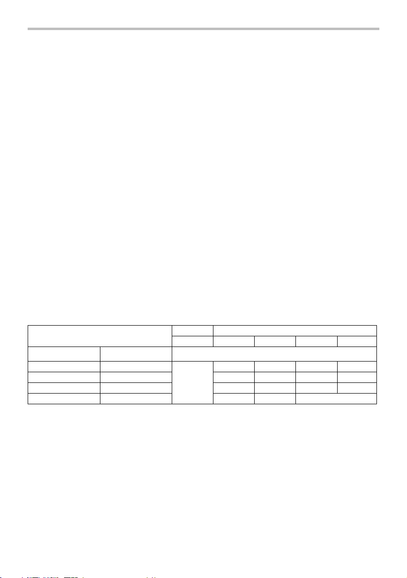
INSTALLATION
Positioning table saw
1. Hole diameter 8
mm (5/16")
620 mm
(24-9/16")
1
(20-5/8")
525 mm
006224
4
Page 5
1
25 mm
(1")
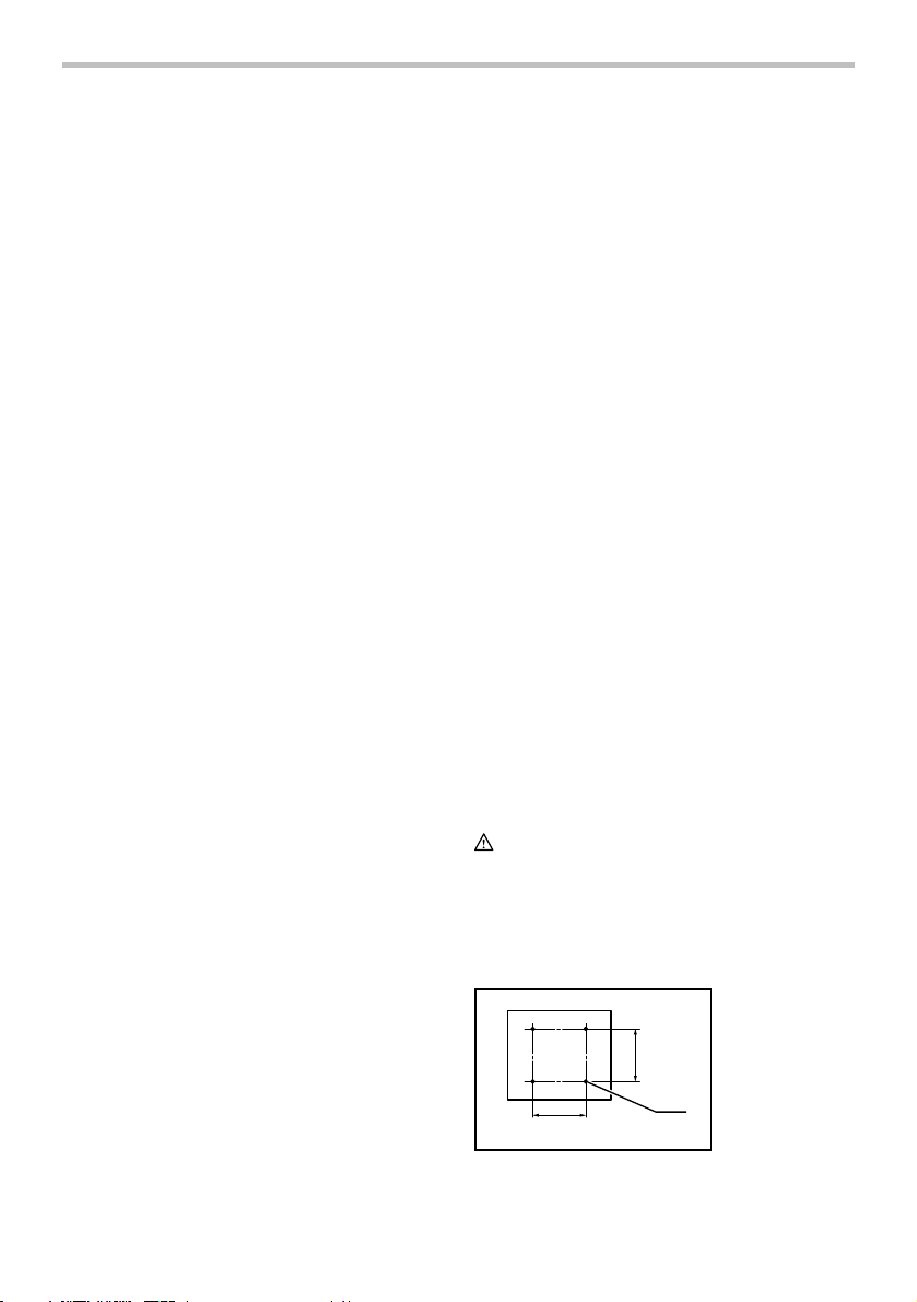
1. 6 mm (1/4") Std.
washer
2. No.10 wood
screw 40 mm
(1-1/2") min.
length
2
006146
1. 6 mm (1/4") Std.
washer
2. 6 mm (1/4")
Mounting bolt &
1
006148
Nut tighten
securely
2
Locate the table saw in a well lit and level area where
you can maintain good footing and balance. It should be
installed in an area that leaves enough room to easily
handle the size of your workpieces. The table saw
should be secured with four screws or bolts to the work
bench or table saw stand using the holes provided in the
bottom of the table saw. When securing the table saw on
the work bench, make sure that there is an opening in
the top of the work bench the same size as the opening
in the bottom of the table saw so the sawdust can drop
through.
If during operation there is any tendency for the table
saw to tip over, slide or move, the work bench or table
saw stand should be secured to the floor.
FUNCTIONAL DESCRIPTION
CAUTION:
• Always be sure that the tool is switched off and
unplugged before adjusting or checking function on
the tool.
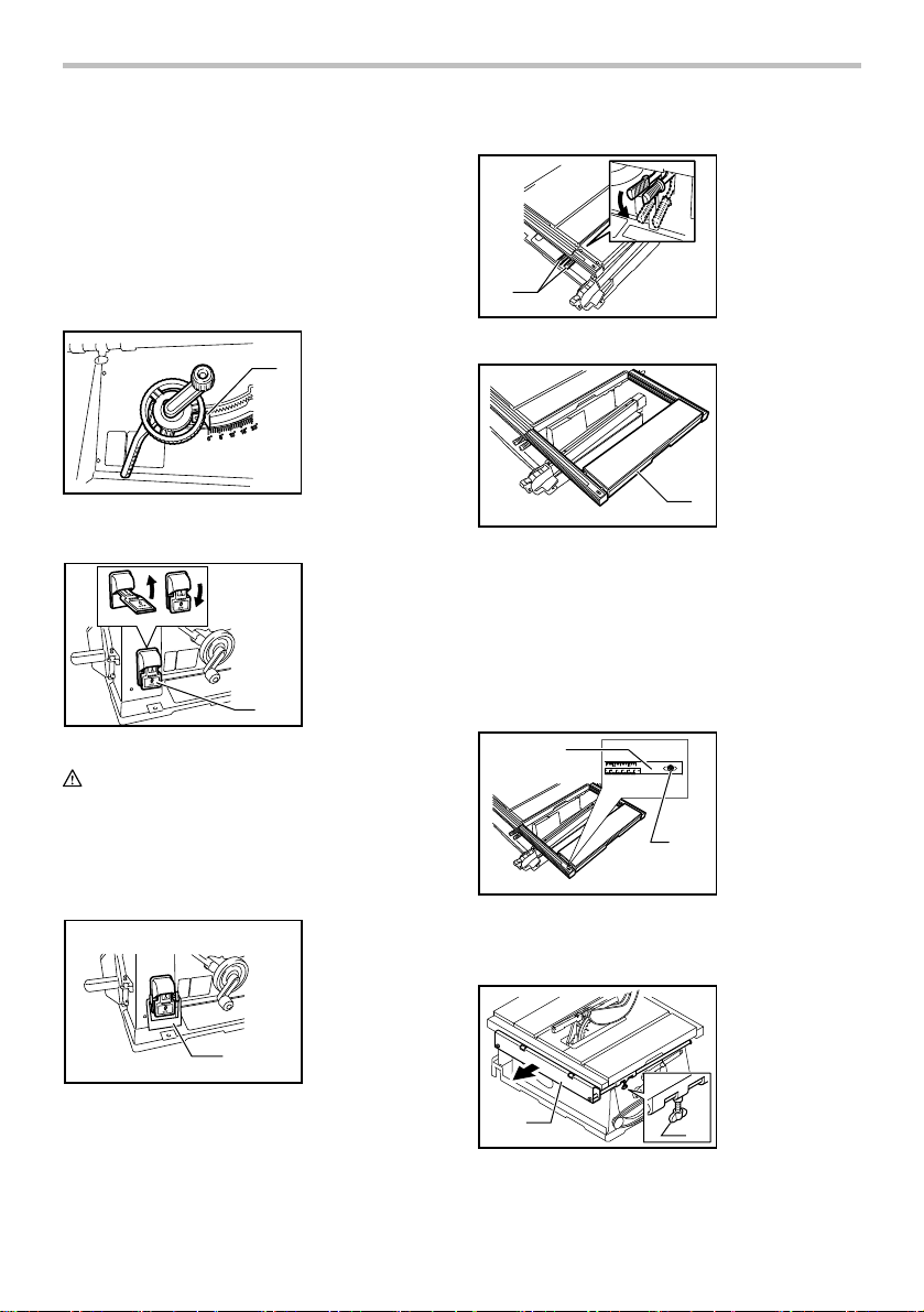
Adjusting the depth of cut
1. Handle
The depth of cut may be adjusted by turning the handle.
Turn the handle clockwise to raise the blade or
counterclockwise to lower it.
NOTE:
• Use a shallow depth setting when cutting thin
materials in order to obtain a cleaner cut.
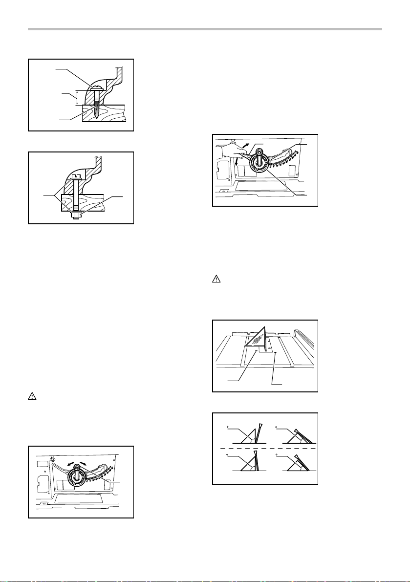
Adjusting the bevel angle
1
006155
Loosen the lock lever counterclockwise and turn the
handwheel until the desired angle (0° - 45°) is obtained.
The bevel angle is indicated by the arrow pointer.
After obtaining the desired angle, tighten the lock lever
clockwise to secure the adjustment.
CAUTION:
• After adjusting the bevel angle, be sure to tighten
the lock lever securely.
1. Lock lever
2
2. Arrow pointer
3. Handwheel
3
Adjusting positive stops
1. 90 ゚ Adjusting
screw
2. 45 ゚ Adjusting
screw
1
006156
(A)
90
90
2
45
45
006154
1
(B)
006157
The tool is equipped with positive stops at 90° and 45° to
the table surface. To check and adjust the positive stops,
proceed as follows:
5
Page 6
Move the handwheel as far as possible by turning it.
Place a triangular rule on the table and check to see if
the blade is at 90° or 45° to the table surface. If the blade
is at an angle shown in Fig. A, turn the adjusting screws
clockwise; if it is at an angle shown in Fig. B, turn the
adjusting screws counterclockwise to adjust the positive
stops.
After adjusting the positive stops, set the blade at 90° to
the table surface. Then adjust the arrow pointer so that
its right edge is aligned to the 0° graduation.
1. Arrow pointer
1
Sub table (R)
1
008753
1. Lever
1. Sub table (R)
006158
Switch action
1. Switch
ON
OFF
1
006217
CAUTION:
• Before plugging in the tool, always be sure that the
tool is switched off.
To start the tool, raise the switch lever. To stop it, lower
the switch lever.
The hinged switch lever plate can be locked by passing
padlock through the hasp on the left hand side.
1
006216
1. Padlock
1
008754
This tool is provided with the sub table (R) on the right
side of the main table. To use the sub table (R), raise
both levers on the front right side, pull out the table (R)
fully and then lower the levers to secure it.
When using the sub table (R ), locate the scale plate on
the sub table after loosening the screw on it with a
screwdriver so that it becomes successive with the scale
plate on the main table.
1
008755
1. Scale plate
2. Screw
2
Sub table (back) and sub table (L) (BOTH
optional accessories)
1. Sub table (back)
2. Screw
1
008729
2
6
Page 7
To use the sub table (back), loosen the screws on the left
g
and right hand sides under the table and pull it out
backwards to the desired length. At the desired length,
tighten the screw securely.
NOTE:
• When using the sub table (back ) during use of the
rip fence, pull out the sub table (back) more than
50 mm so that it does not hit against the top end of
the rip fence.
1. Screw
1
2. Sub table (L)
2
1
006151
Sub table (back) can be installed at the back of the table
to assure wider space. Sub table (L) can be installed on
the left side of the table.
ASSEMBLY
Overview of Table Saw Blade Guarding
System
5
008941
1
2
4
WARNING:
• Always be sure that the tool is switched off and
unplugged before carrying out any work on the
tool.
The saw blade and blade guard are not installed on the
tool when it is shipped from the factory.
Installing or removing saw blade
WARNING:
• Always be sure that the tool is switched off and
unplugged before installing or removing the blade.
• Use only the Makita socket wrench provided to
install or remove the blade. Failure to do so may
result in overtightening or insufficient tightening of
the hex bolt. This could cause an injury.
1. Table saw blade
guard assembly
2.
Antikickback pawls
3. Riving
knife/spreader
4.
Riving knife/
spreader release
lever location
5. Table saw blade
3
side
uards
1. Wrench
2. Hex nut
1
3. Offset wrench
3
008730
2
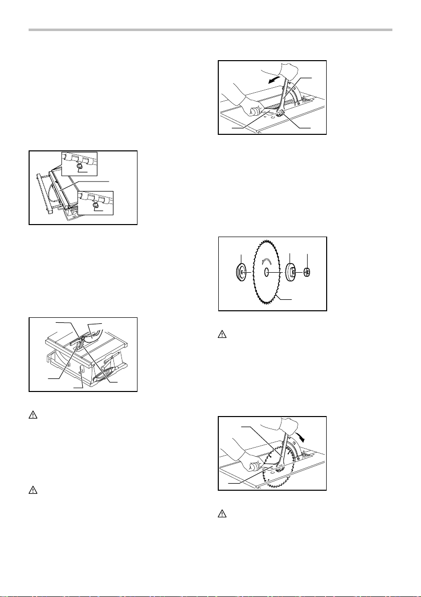
Remove the table insert on the table. Hold the outer
flange with the offset wrench and loosen the hex nut
counterclockwise with the wrench. Then remove the
outer flange.
Assemble the inner flange, blade, outer flange and hex
nut onto the arbor, making sure that the teeth of the
blade are pointing down at the front of the table. Always
install the hex nut with its recessed side facing the outer
flange.
1. Inner flange
12
4
2. Outer flange
3. Saw blade
4. Hex nut
3
006136
CAUTION:
• Keep the flange surface clean of dirt or other
adhering matter; it could cause blade slippage. Be
sure that the blade is installed so that the teeth are
aligned in the cutting (turning) direction.
To secure the blade in place, hold the outer flange with
the offset wrench, then tighten the hex nut clockwise
with the wrench. BE SURE TO TIGHTEN THE HEX NUT
SECURELY.
1
2
008731
1. Wrench
2. Offset wrench
CAUTION:
• Be sure to hold the hex nut carefully with the
wrench. If your grip should slip, the wrench may
come off the hex nut, and your hand could strike
7
Page 8
the sharp blade edges.
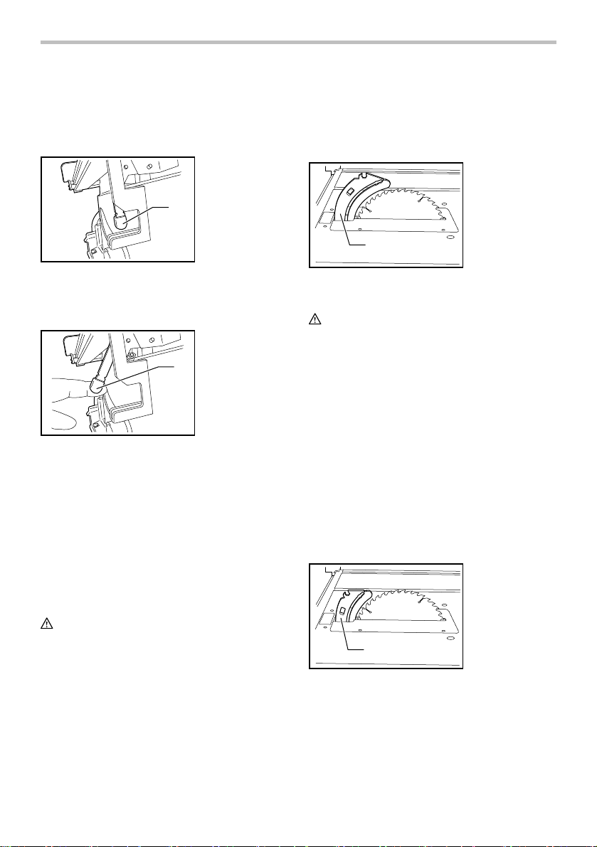
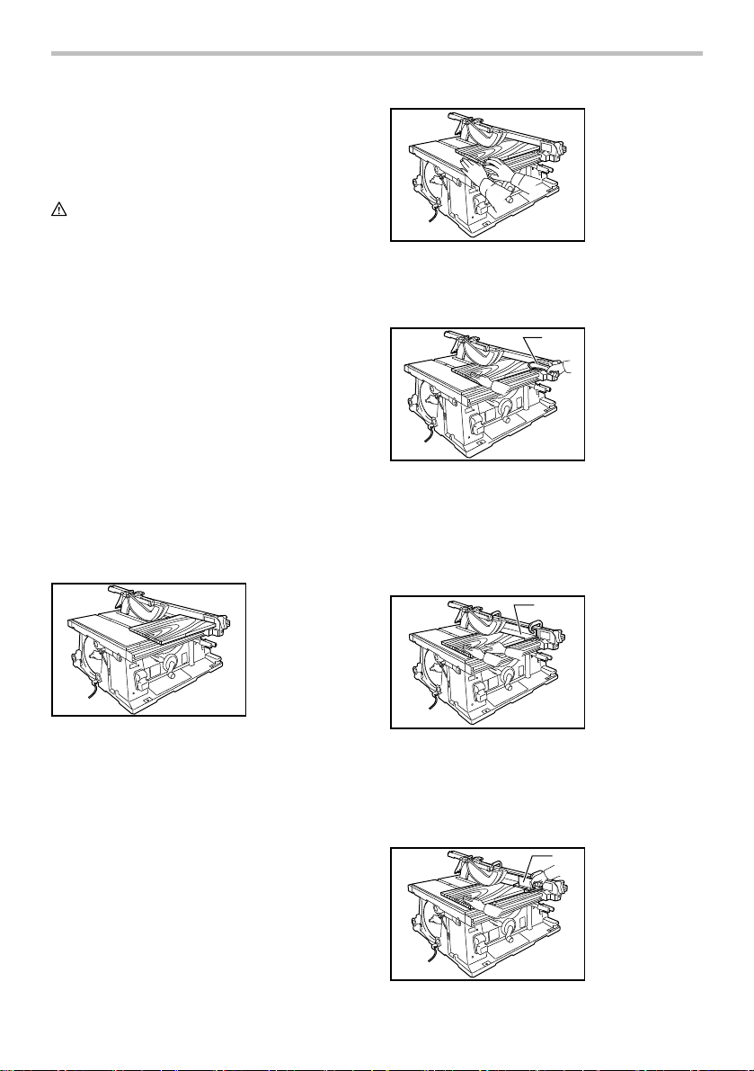
Riving Knife/Spreader Positioning
1. Locate the riving knife/spreader release lever
located at the back of the table saw as shown in
figure 1.
1. Riving Knife/
Spreader
Release Lever
1
lever located at the back of the table saw has returned
to the position as shown in figure 1. Before mounting the
guard be sure to check that the riving knife/spreader unit
is in a locked position by pulling up and pushing down on
the unit to ensure there is no movement.
Spreader Position
1. Riving Knife/
Spreader in
Spreader
Position
Fig.1
008748
2. Pull the riving knife/spreader release lever until it
stops as shown in figure 2. This action will release
the riving knife/spreader for positioning.
1. Pull the Riving
Knife/Spreader
release Lever
1
Fig.2
008749
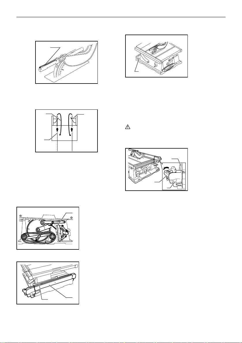
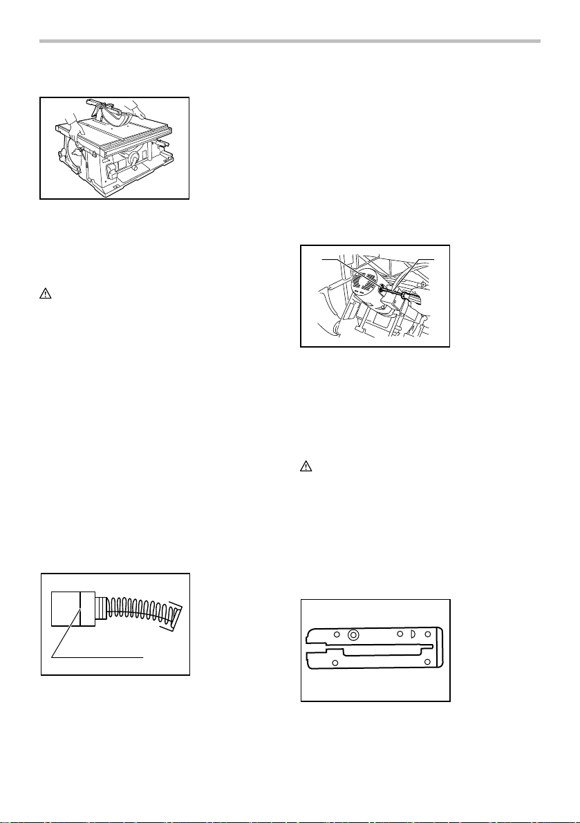
3. With the release lever pulled move the riving
knife/spreader up or down by hand to the desired
position. Once the riving knife/spreader begins
to move release the lever and continue to move
the riving knife/spreader to the next setting and it
will automatically lock into position. The riving
knife/spreader is able to lock into 3 positions as
shown in figures 3-5 below.
Three Operating Positions of the Riving
Knife/Spreader Unit
Spreader Position
WARNING:
• This position is used for through-cutting
operations and the guard assembly with the
side guards should always be used for this
type of operation. Conducting a through-cut
without proper guarding may result in serous
personal injury.
The riving knife/spreader unit can be made ready for the
attachment of the guard assembly and side guards by
positioning it at the maximum adjustable height as
shown in Fig 3. In this position the unit is raised above
the blade so that the guard assembly can be installed
and made operational. Make sure that the release
1
008750
Fig.3
Riving Knife Position
WARNING:
• Never Operate The Saw With The Guard
Mounted To The Riving Knife/ Spreader When
The Riving Knife/ Spreader Unit Is In The Riving
Knife Position. The guard may interfere with the
feeding of the work piece and could result in
kickback and serious injury.
The riving knife/spreader unit can be positioned and
locked at a height setting that is just below the top of the
saw blade as shown in figure 4. The unit would be
used in this position for non-through cutting operations
with the guard removed such as rabbets and groove
cutting. Make sure that the release lever located at the
back of the table saw has returned to the position as
shown in figure 1. Before operating the tool be sure to
check that the riving knife/spreader unit is in a locked
position by pulling up and pushing down on the unit to
ensure there is no movement
Riving Knife Position
1. Riving Knife/
Spreader in
Riving Knife
Position
1
008751
Fig.4
Dado Position
The riving knife/spreader unit can be positioned and
locked at a setting that is just below the table behind the
blade as shown in figure 5. This position would only be
used while attempting to perform dado cuts with a dado
type blade. For ease of operation by pulling the riving
knife/spreader release lever the unit will automatically
8
Page 9
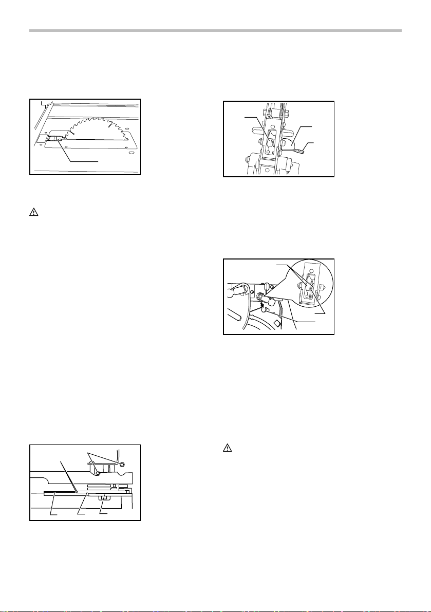
pop up above the table to provide an easy grasping area
g
on the unit so that it can be pulled up from below the
table and moved into the next desired position.
Dado Position
1. Riving knife/
Spreader in
Dado Position
1
Fig.5
008752
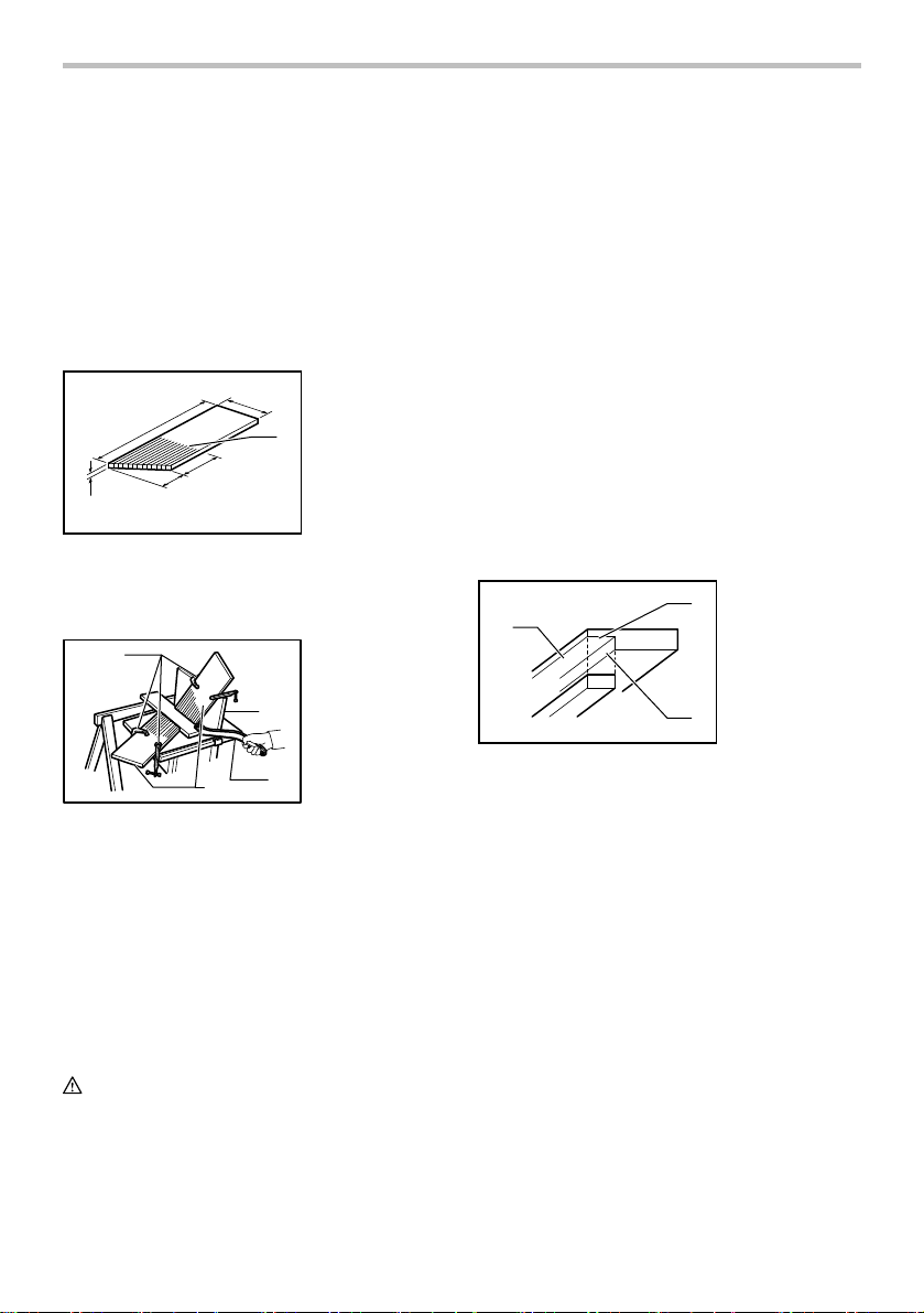
Riving Knife/Spreader Alignment
WARNING:
• Always make sure the blade is properly aligned
with the riving knife / spreader. If the blade and
the riving knife / spreader are not aligned this could
cause interference with the feeding and/or the
pinching of the work piece resulting in a kickback
situation and possible serious personal injury.
• NEVER make any adjustments while the tool is
running. Always disconnect the tool before
making any adjustments, accidental start up of the
tool could result in serious personal injury.
The riving knife / spreader installation is factory-adjusted
so that the blade and the riving knife / spreader are
properly aligned. However, if the blade and the riving
knife / spreader come out of alignment this can be
corrected by first unplugging the tool to prevent
unintentional operation. Then the hex bolts as shown
in item 5 should be loosened using the specially
provided wrench. With the hex bolts loosened adjust
the riving knife/spreader so that it is aligned directly
behind the blade while maintaining equal clearance on
either side of the riving knife / spreader in relation to the
blade as shown in item 1. Once the riving knife
spreader is located properly lock the mounting means
into place by tightening the hex bolts as shown in item 5.
1. These two
clearances
should be equal
2. Blade
3. Riving knife/
Spreader
4. Pressure plate
5. Hex bolts
009009
5
1
4
3
2
Blade Guard Assembly Installation or
Removal
1. Release the locking lever pin of the blade guard
by lifting the locking lever tab as shown in figure 1.
1. Locking Lever in
3
008742
1
2
Fig.1
2. For ease of guard assembly installation adjust the
table saw for maximum depth of cut. With the
locking lever released as shown in Figure 1,
position the locking lever pin center groove into
the notch provided on the riving knife/spreader
unit as shown in figure 2.
Fig.2
008743
2
3
3. Once the locking lever pin is placed into the riving
knife/spreader notch it is to be locked into position
by pushing the tab of the pin's locking lever into
the locked position as shown in Figure 3. Once
the pin's locking lever is in the locked position
check to ensure that the guard assembly is
properly attached to the riving knife/spreader
assembly by pulling up on the guard assembly
and making sure it does not move its position.
WARNING:
• Always ensure proper attachment of the guard
assembly to the Riving Knife/Spreader before
turning the saw on. Improper attachment of the
guard assembly could result in the saw blade
making contact with the guard, causing serious
injury.
the released
position
2. Locking Lever
tab
3. Locking Lever
Pin
1.
The notch
provided on the
Riving Knife/
Spreader for the
locking lever pin
center groove
2. Locking lever pin
sleeves
1
3. Locking lever pin
center
roove
9
Page 10
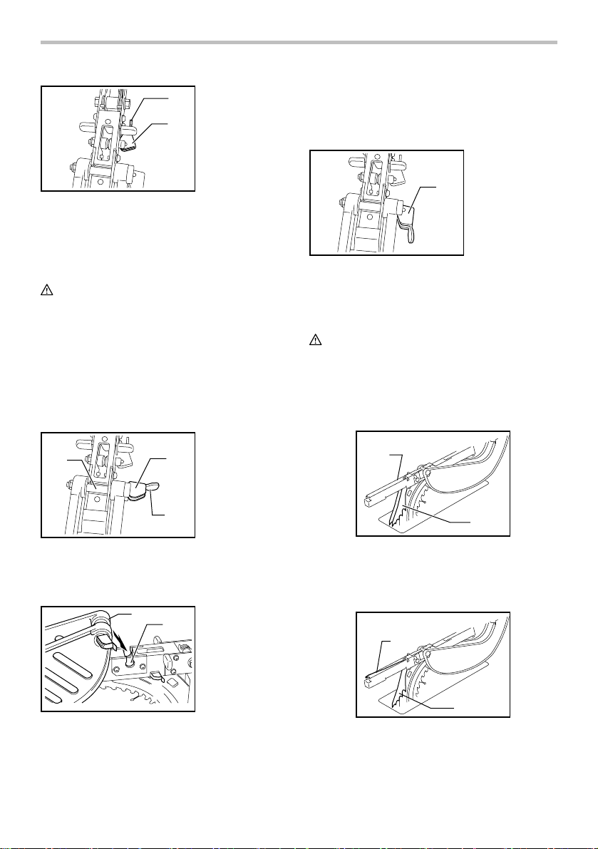
Fig.3
008744
To remove the blade guard for non through cutting
operations reverse the above steps 1 - 3.
1. Locking Lever in
2
the locked
1
position
2. Locking Lever
tab
Installation of Side Guards to Blade Guard
Assembly
WARNING:
• The guard assembly and side guards should
only be used with the riving knife/spreader in
the spreader position to prevent guard
interference with the work pieces. The use of
the guard assembly with the riving knife/spreader
in the riving knife position may cause interference
with the work piece resulting in a kickback situation
and possible serious personal injury.
1. Release the locking lever pin of the side guard by
lifting the locking lever tab as shown in figure 1.
Side Guard
1.
3
008745
2. With the locking lever pin released position the pin
into the notch provided on the blade guard
assembly as shown in figure 2.
Fig.2
008746
1
2
Fig.1
2
1
Locking Lever in
the released
position
2.
Side Guard
Locking Lever
Ta b
Side Guard
3.
Locking Lever Pin
1. The Notch
provided in the
Blade Guard
Assembly
2. Place locking
lever pin into the
blade guard
assembly
3. Once the locking lever pin is placed into the notch
provided on the blade guard assembly it is to be
locked into position by pushing the tab of the pin's
locking lever into the locked position as shown in
Figure 3.
1. The locking
lever in the
locked position
1
Fig.3
008747
To remove the blade guard for non through cutting
operations reverse the above steps 1-3.
Antikickback Pawl Operation
WARNING:
• Use the Antikickback pawls whenever possible
during the through cutting operations. This will
help prevent the material from being pushed
forward into the operator during a kickback
situation which may result in serious personal
injury.
Fig.1
1
The blade guard assembly item 1 is provided with two on
board antikickback pawls item 2. The pawls are located
on either side of the blade and can be stored or put into
operation independently for ease of operation
008936
1
Item 1 illustrates the antikickback pawl on the right side
of the blade being lifted and placed into the pawl holder
located at the back of the blade guard assembly.In
addition item2 illustrates the antikickback pawl on the left
side of the blade remaining in the operational position.
008937
10
2
2
Fig.2
Page 11
1
1. Table saw blade
guard assembly
and side guard
storage
Fig.3
1
Fig.4
Item 1 demonstarates both antikickback pawls being
lifted and placed into the pawl holders located at the
back of the blade guard assembly for storage
008938
2
3
Item 1 indicates the location of the antikickback pawl
holders located at the back of the blade guard assembly
Item 2 points to the arrow direction which should be
followed when taking the pawls out of the storage
position and placing them into operation
Item 3 indicates the direction of which the pawls should
be lifted when storing and placing them into the
antikickback pawl holders
008939
Storage of Blade Guards and Accessories
1. Miter gauge
1
006152
2
006153
1. Rip fence
2. Push stick
1
1
009010
The miter gauge, blade and wrenches can be stored on
the left side of the base and the rip fence can be stored
at the right side of the base. The Blade Guard
Assembly and Side Guards can be stored independently
in the pocket provided on the right side of the table base.
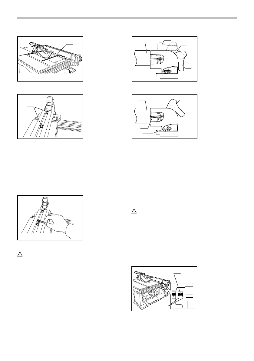
Installing and adjusting rip fence
WARNING:
• Always be sure the tool is switched off and
unplugged before attempting to perform the
installation and adjustment of the rip fence.
1
2
008732
1) Fit the hook on the tip of the rip fence into the far
guide rail on the table or sub table (R) and install and
push the rip fence forward so that the fence holder
engages with the nearmost guide rail.
To slide the rip fence on the guide rail sideways, pivot
the knob on the fence holder to the half way of its travel.
To secure the rip fence, pivot fully the knob on the fence
holder.
2) To slide the rip fence on the guide rail sideways,
return the knob on the fence holder fully without pulling
the lever on the knob.
3) To remove it, pull the lever on the knob and pivot the
knob fully forward while pulling the lever.
To check to be sure that the rip fence is parallel with the
blade, secure the rip fence 2 - 3 mm (5/64" - 1/8" ) from
the blade. Raise the blade up to maximum elevation.
Mark one of the blade teeth with a crayon. Measure the
distance (A) and (B) between the rip fence and blade.
Take both measurements using the tooth marked with
the crayon. These two measurements should be
identical. If the rip fence is not parallel with the blade,
proceed as follows:
3
1. Guide rail
2. Knob
3. Hook
11
Page 12
1. Scale
A
1
B
1
2
1. Rip fence
2. Released
3
position
3. Moving position
4. Lock position
4
008733
1
006161
1. Position the rip fence in the sliding position.
2. Loosen the two hex bolts on the rip fence with the
hex wrench provided.
3. Adjust the rip fence until it becomes parallel with
the blade.
4. Pivot down the knob on the rip fence toward the
operator.
5. Tighten the two hex bolts on the rip fence.
006215
WARNING:
• Be sure to adjust the rip fence so that it is parallel
with the blade, or a dangerous kickback condition
may occur.
When the rip fence cannot be secured solidly, adjust it
according to the following procedure.
(1) Set the rip fence on the table and then pivot
the knob half way through its rotation. Tighten
the screw (A) until the rip fence is
immobilized. Then loosen a 1/4 to 1/2 turn.
1. Hex bolts
007778
1
3
4
007779
(2) Tighten the screw (B) fully and then loosen
about 2 full revolutions.
(3) Lock the rip fence by fully pivoting the knob
on the fence holder (lock position).
(4) Make sure that the rip fence can be installed
and removed in the original position
(released position).
(5) Make sure that the rip fence can be slid
smoothly with no wobble when the knob is
• Be careful not to tighten screws with more than the
Bring the rip fence up flush against the side of the blade.
Make sure that the guideline on the fence holder points
to the 0 graduation. If the guideline does not point to the
0 graduation, loosen the screw on the scale plate and
adjust the scale plate.
008734
rotated half way through its rotation.
CAUTION:
tightening amount specified in the above
instructions. Failure to do so may damage the
fastened parts.
2
1. Rip fence
2
2. Moving position
3. Screw (B)
4. Screw (A)
1. Guideline
1
2. Screws
12
Page 13
OPERATION
CAUTION:
• Always use "work helpers" such as push sticks and
push blocks when there is a danger that your
hands or fingers will come close to the blade.
• Always hold the workpiece firmly with the table and
the rip fence or miter gauge. Do not bend or twist it
while feeding. If the workpiece is bent or twisted,
dangerous kickbacks may occur.
• NEVER withdraw the workpiece while the blade is
running. If you must withdraw the workpiece before
completing a cut, first switch the tool off while
holding the workpiece firmly. Wait until the blade
has come to a complete stop before withdrawing
the workpiece. Failure to do so may cause
dangerous kickbacks.
• NEVER remove cut-off material while the blade is
running.
• NEVER place your hands or fingers in the path of
the saw blade. Be especially careful with bevel
cuts.
• Always secure the rip fence firmly, or dangerous
kickbacks may occur.
• Always use "work helpers" such as push sticks and
push blocks when cutting small or narrow
workpieces, or when the dado head is hidden from
view while cutting.
Work helpers
Push sticks, push blocks or auxiliary fence are types of
"work helpers". Use them to make safe, sure cuts
without the need for the operator to contact the blade
with any part of the body.
NOTE:
• For your convenience a push stick has been
provided with the tool.
Push stick
1. Workpiece end
19mm
(3/4")
400mm
1
38mm
(1-1/2")
008756
6.35mm
(1/4")
(15-3/4")
6.35mm
(1/4")
6.35mm
(1/4")
Make the push stick using a piece of 1" x 2" as shown in
the figure.
2. 45 ゚ notch
2
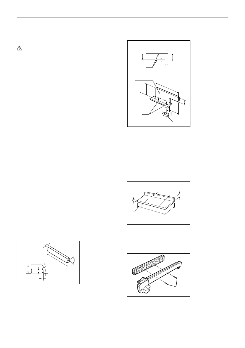
Push block
1. Face/edge
parallel
2. Handle
3. Wood screw
4. Glue together
50mm
(2")
100mm
(4")
120mm
(4-3/4")
2
006219
130mm
(5")
3
1
300mm(12")
6mm
(1/4")
9.5mm
(3/8")
50mm
(2") 8mm(5/16")
130mm(5")
50mm(2")
300mm(12")
4
Use a 19 mm (3/4") piece of plywood.
Handle should be in center of plywood piece. Fasten
with glue and wood screws as shown. Small piece 9.5
mm x 8 mm x 50 mm (3/8" x 5/16" x 2") of wood must
always be glued to plywood to keep the blade from
dulling if the operator cuts into push block by mistake.
(Never use nails in push block.)
Auxiliary fence
9.5mm
(3/8")
1
006211
19mm
(3/4")
460mm
(18")
120mm
(4-3/4")
140mm
(5-1/2")
1. Face/edge
parallel
40mm
(1-1/2")
Make auxiliary fence from 9.5 mm (3/8") and 19 mm
(3/4") plywood pieces.
Wood facing (rip fence)
1. No. 10 wood
screws (long
enough to
penetrate
halfway into
facing)
1
006165
13
Page 14
A wood facing should be used for operations when the
blade comes close to the rip fence. Wood facing for the
rip fence should be the same size as the rip fence. Make
sure the bottom of facing is flush with the table surface.
Ripping
CAUTION:
• When ripping, remove the miter gauge from the
table.
• When cutting long or large workpieces, always
provide adequate support behind the table. DO
NOT allow a long board to move or shift on the
table. This will cause the blade to bind and
increase the possibility of kickback and personal
injury. The support should be at the same height as
the table.
Before operating the table saw, check to be sure that the
antikickback pawls operate properly. Turn the tool off
and unplug it. Feed the workpiece under the blade guard
and along both sides of the blade to simulate cutting. Try
to withdraw the workpiece on each side by pulling it
toward you. The antikickback pawls should grab the
workpiece and prevent it from moving back toward the
operator. Always keep the antikickback pawls sharp so
they will operate properly. Keep them sharp by using a
round-shaped file to maintain the original shape of the
pawls.
1. Adjust the depth of cut a bit higher than the
thickness of the workpiece.
008736
(2) When the width of rip is 65 mm - 150 mm
(2-1/2" - 6") wide, use the push stick to feed
the workpiece.
1. Push stick
1
008737
(3) When the width of rip is narrower than 65 mm
(2-1/2"), the push stick cannot be used
because the push stick will strike the blade
guard. Use the auxiliary fence and push block.
Attach the auxiliary fence to the rip fence with
two "C" clamps.
1
1. Auxiliary fence
008735
2. Position the rip fence to the desired width of rip
and lock in place by pivoting the grip. Before
ripping, make sure the rear end of the rip fence is
secured firmly. If it is not secured enough, follow
the procedures in the section titled "Installing and
adjusting rip fence".
3. Turn the tool on and gently feed the workpiece
into the blade along with the rip fence.
(1) When the width of rip is 150 mm (6") and
wider, carefully use your right hand to feed
the workpiece. Use your left hand to hold the
workpiece in position against the rip fence.
14
008738
008739
Feed the workpiece by hand until the end is
about 25 mm (1") from the front edge of the
table. Continue to feed using the push block
on the top of the auxiliary fence until the cut is
complete.
1
1. Push block
Page 15

Cross cutting
CAUTION:
• When making a crosscut, remove the rip fence
from the table.
• When cutting long or large workpieces, always
provide adequate support to the sides of the table.
The support should be at the same height as the
table.
• Always keep hands away from path of blade.
Miter gauge
12
34
006166
1. CROSS
CUTTING
2. MITERING
3. BEVEL
CUTTING
4. COMPOUND
MITERING
(ANGLES)
Use the miter gauge for the 4 types of cutting shown in
the figure.
CAUTION:
• Secure the knob on the miter gauge carefully.
• Avoid movement of the workpiece and gauge by
firmly securing the workpiece and gauge,
especially when cutting at an angle.
• NEVER hold or grasp the intended "cut-off" portion
of the workpiece.
Miter gauge positive stop
3
2
1. Knob
2. Small plate
3. Screw for
positive stop
1
006225
Miter gauge is provided with positive stops at 90°,
45°right and left miter angles for quick setting of miter
angles.
To set the miter angle, loosen the knob on the miter
gauge.
Raise the small plate on the miter gauge for free setting.
Turn the miter gauge to the desired miter angle. Return
the small plate on the miter gauge to the original position
and tighten the knob clockwise securely.
Use of miter gauge
1
2
1. Groove
2. Knob
3. Miter gauge
3
008740
Slide the miter gauge into the thick grooves in the table.
Loosen the knob on the gauge and align to desired
angle (0° to 60°). Bring stock flush up against fence and
feed gently forward into the blade.
Auxiliary wood facing (miter gauge)
006168
To prevent a long board from wobbling, fit the miter
gauge with an auxiliary fence board. Fasten with
bolts/nuts after drilling holes, but fasteners must not
protrude from the face board.
Non-through cut
Turn off the tool and unplug it before any adjustment.
Remove the blade guard assembly from the riving
knife/spreader.
Adjust the riving knife/spreader to the RIVING KNIFE
POSITION as described earlier in the manual. Before
making a through cut adjust the riving knife/spreader to
the spreader position and install the blade guard
assembly and the side guards before operation.
WARNING:
• Conducting a through cut without proper
guarding may result in serious personal injury.
15
Page 16
Carrying tool
008741
Carry the tool by holding the tool part shown in the
figure.
MAINTENANCE
WARNING:
• Always be sure that the tool is switched off and
unplugged before attempting to perform
inspection or maintenance.
Cleaning
Clean out sawdust and chips from time to time. Carefully
clean the blade guard and moving parts inside the table
saw.
Lubrication
To keep the table saw in tip-top running condition, and to
assure maximum service life, oil or grease the moving
parts and rotating parts from time to time.
Lubrication places:
• Threaded shaft to elevate the blade
• Hinge to rotate the frame
• Elevation guide shafts on motor
• Gear to elevate the blade
• Guide rails for the rip fence
• Shaft of the sub table (R) locking levers
• Sliding part of the sub table (R)
Replacing carbon brushes
1. Limit mark
Use a screwdriver to remove the brush holder caps. To
replace the carbon brushes, remove the blade guard
and blade and then loosen the lock lever, tilt the saw
head and secure it at 45° bevel angle. Carefully lay the
tool on itself backward. Then loosen the brush holder
cap. Remove the worn carbon brushes, insert the new
ones and secure the brush holder caps.
After replacing brushes, plug in the tool and break in
brushes by running tool with no load for about 10
minutes. Then check the tool while running and electric
brake operation when releasing the switch trigger. If
electric brake is not working well, ask your local Makita
service center to repair.
1. Brush holder
1
006173
2
cap
2. Screwdriver
To maintain product SAFETY and RELIABILITY, repairs,
any other maintenance or adjustment should be
performed by Makita Authorized or Factory Service
Centers, always using Makita replacement parts.
ACCESSORIES
WARNING:
• These accessories or attachments are
recommended for use with your Makita tool
specified in this manual. The use of any other
accessories or attachments might present a risk of
injury to persons. Only use accessory or
attachment for its stated purpose.
If you need any assistance for more details regarding
these accessories, ask your local Makita Service Center.
Table insert (Part No. 317934-3)
1
001145
Remove and check the carbon brushes regularly.
Replace when they wear down to the limit mark. Keep
the carbon brushes clean and free to slip in the holders.
Both carbon brushes should be replaced at the same
time. Use only identical carbon brushes.
006176
It is required to use this Table Insert for dado head sets.
Use of the standard table insert will interfere with the
dado head set operation.
16
Page 17
To install the dadao head set, proceed as follows.
1. Remove the blade guard assembly.
2. Remove the standard table insert.
3. Place riving knife/spreader into the dado position.
4. Install the dado head set according to
manufacturer's instructions.
5. Place the table insert for dado cutting into the
table.
When dadoing, use featherboards. The diagram shown
illustrates dimensions for making a typical featherboard.
It should be made from a straight piece of wood that is
free of knots or cracks.
1. Kerf should be
(8")
about 6 mm
(1/4") apart
1
(5")
19 mm
006180
600 mm
(24")
(3/4")
130 mm
115 mm
(4-1/2")
200 mm
Featherboards are used to keep the workpiece in
contact with the rip fence and table as shown, and to
stop kickbacks.
1
4
006182
1. C clamps
2. Facing board
3. Push stick
4. Featherboard
2
3
To install featherboards, proceed as follows:
6. Turn the tool off and unplug it.
7. Add 8" high flat facing board to the rip fence, the
full length of the rip fence.
8. Mount featherboards to the rip fence and table as
shown, so that the leading edges of the
featherboards will support the workpiece until the
cut is completed, and the workpiece has been
pushed completely past the cutter with a push
stick.
9. Make sure featherboards are securely attached.
WARNING:
• Do not use dado headsets wider than 21mm
(13/16") or dados greater than 6" in outmost
diameter.
• After dadoing, ALWAYS properly adjust the riving
knife/spreader and replace the blade guard
assembly and side guards for through cuts.
• NEVER attempt bevel cuts when dadoing.
• NEVER dado if there is vibration (flutter) or a
strange noise.
• Feed work slowly, especially when cutting deep or
wide grooves or dados. If a deep cut is needed,
make several passes through the workpiece rather
than one deep, wide cut. Fast or abrupt feeds can
be dangerous.
• Use a push stick. When the dado head is hidden
from view while cutting, your hands should never
be on top of the stock.
• A very dangerous throwback can result if the wood
becomes stuck and you try to remove it by pulling
toward you. Always stop the tool and wait for dado
head to come to a complete stop. Then simply
withdraw the wood.
• Use extra caution when the guard assembly is
removed for any non-through sawing operation
such as dadoing, rabbeting or re-sawing. Adjust
the riving knife/spreader and replace the guard
assembly and side guards.
How to perform rabbeting
1. Rabbet
2
2. Second cut
1
006183
1. Remove blade guard assembly and properly
adjust the riving knife/spreader to the riving knife
poisiton.
2. Attach auxiliary fence to rip fence for cuts that run
the length of the stock. Facing should be as high
as the workpiece is wide. Adjust fence and blade
to desired dimensions.
3. First cut: Hold board flat on table as in ordinary
ripping.
4. Second cut: Set workpiece on its edge. (Use
featherboards, push stick, push block and so on,
using precautions, safety rules and guidelines for
ripping or related work.)
5. For end-type rabbeting, if the workpiece is less
than 10-1/2" wide, rest the wood flat on the table
against the miter gauge (with wood facing). The
rip fence should not be used.
6. When moving from a rabbet cut operation to a
through cut operation adjust the riving
knife/spreader to the spreader position and install
the guard assembly and side guards.
17
3. First cut
3
Page 18

Table stand set (accessory)
Refer to the instruction manual for table saw stand that
is provided with the table saw stand as an optional
accessory.
• Steel & Carbide-tipped saw blades
Table/Miter saw
blades
Combination
Fine cross cuts For sand-free cuts cleanly against the grain.
006586
• Sub table ( L)
• Sub table ( back)
• Rip fence
• Miter gauge
• Offset wrench 13-22
• Wrench 19
• Hex wrench 5
• Auxiliary plate
• Stand set
• Sliding guide
For general purpose cuts for table and miter saws.
General purpose blade for fast and smooth rip,
crosscuts and miters.
MAKITA LIMITED ONE YEAR WARRANTY
Warranty Policy
Every Makita tool is thoroughly inspected and tested
before leaving the factory. It is warranted to be free of
defects from workmanship and materials for the period
of ONE YEAR from the date of original purchase.
Should any trouble develop during this one year period,
return the COMPLETE tool, freight prepaid, to one of
Makita’s Factory or Authorized Service Centers. If
inspection shows the trouble is caused by defective
workmanship or material, Makita will repair (or at our
option, replace) without charge.
This Warranty does not apply where:
repairs have been made or attempted by others:
repairs are required because of normal wear and
tear:
the tool has been abused, misused or improperly
maintained:
alterations have been made to the tool.
IN NO EVENT SHALL MAKITA BE LIABLE FOR ANY
INDIRECT, INCIDENTAL OR CONSEQUENTIAL
DAMAGES FROM THE SALE OR USE OF THE
PRODUCT. THIS DISCLAIMER APPLIES BOTH
DURING AND AFTER THE TERM OF THIS
WARRANTY.
MAKITA DISCLAIMS LIABILITY FOR ANY IMPLIED
WARRANTIES, INCLUDING IMPLIED WARRANTIES
OF "MERCHANTABILITY" AND "FITNESS FOR A
SPECIFIC PURPOSE," AFTER THE ONE YEAR TERM
OF THIS WARRANTY.
This Warranty gives you specific legal rights, and you
may also have other rights which vary from state to
state. Some states do not allow the exclusion or
limitation of incidental or consequential damages, so
the above limitation or exclusion may not apply to you.
Some states do not allow limitation on how long an
implied warranty lasts, so the above limitation may not
apply to you.
EN0006-1
18
Page 19

FRANÇAIS
SPÉCIFICATIONS
Modèle 2705
Alésage central 15.88 mm (5/8")
Diamètre de la lame 255 mm (10")
Caractéristiques liées au
couteau diviseur
Capacités de coupe max.
Capacités d'embrèvement maximales 21 mm (13/16")
Vitesse à vide (T/MIN) 4,800/min
Dimensions de la table (L x P)
Dimensions (L x P x H) avec table non déployée
• Étant donné l'évolution constante de notre programme de recherche et de développement, les spécifications contenues dans ce
manuel sont sujettes à modification sans préavis.
• Note : Les spécifications peuvent varier suivant les pays.
Pour votre propre sécurité,
veuillez lire le manuel
d'instructions
Avant d'utiliser l'outil
Conservez-le pour référence
ultérieure
PRÉCAUTIONS GÉNÉRALES
(POUR TOUS LES OUTILS)
1. VOUS DEVEZ CONNAÎTRE VOTRE OUTIL
ÉLECTRIQUE. Lisez attentivement le manuel
d'instructions. Familiarisez-vous avec les
applications et limites de l'outil, ainsi qu'avec
les risques potentiels qui lui sont spécifiques.
2. MAINTENEZ LES PROTECTEURS EN PLACE
et en bon état de fonctionnement.
3. RETIREZ LES CLÉS DE RÉGLAGE ET DE
SERRAGE. Prenez l'habitude de vous assurer
que les clés de réglage et de serrage ont été
retirées de l'outil avant de le mettre sous
Épaisseur de la lame 1.8 mm (1/16")
Épaisseur du couteau diviseur 2.3 mm (3/32")
Diamètre de la lame Max. 255 mm (10 ") - Min. 250 mm (9-7/8 ")
Dimension du trait de scie 2.6 mm (3/32")
90° 91 mm (3-9/16")
45° 63 mm (2-1/2")
567 mm x (753 mm - 1,066 mm)
22-1/4" x (29-5/8" - 42")
678 mm x 766 mm x 344 mm
Poids net 29 kg (64 lbs)
USA007-2
(26-3/4" x 30-1/4" x 13-1/2")
tension.
4. MAINTENEZ LA ZONE DE TRAVAIL PROPRE.
Les zones de travail et les établis encombrés
ouvrent grande la porte aux accidents.
5. ÉVITEZ L'UTILISATION DANS UN
ENVIRONNEMENT DANGEREUX. N'utilisez
pas les outils électriques dans les endroits
humides ou mouillés, et ne les exposez pas à
la pluie. Maintenez un éclairage adéquat dans
la zone de travail. Ne vous servez pas de votre
outil en présence de liquides ou gaz
inflammables.
6. MAINTENEZ LES ENFANTS À L'ÉCART. Toute
autre personne que l'utilisateur de l'outil doit
se tenir à une distance sûre de l'aire de travail.
7. FAITES EN SORTE QUE L'ATELIER SOIT
SANS DANGER POUR LES ENFANTS, en y
posant des cadenas, un interrupteur principal,
ou en retirant des équipements leurs clés de
démarrage.
8. NE FORCEZ PAS L'OUTIL. Il effectuera un
travail de meilleure qualité et plus sécuritaire
s'il est utilisé au régime pour lequel il a été
conçu.
9. UTILISEZ LE BON OUTIL. Ne forcez pas un
outil ou accessoire à effectuer un travail pour
lequel il n'a pas été conçu.
10. PORTEZ DES VÊTEMENTS ADÉQUATS. Ne
portez ni vêtements ni gants amples, ni
cravate, anneaux/bagues, bracelets ou autres
19
Page 20

bijoux susceptibles d'être happés par les
pièces mobiles de l'outil. Le port de
chaussures antidérapantes est recommandé.
Portez un filet de protection pour envelopper
les cheveux longs.
11. PORTEZ TOUJOURS DES LUNETTES DE
20. SENS D'ALIMENTATION. Vous devez faire
SÉCURITÉ. Si le travail de coupe dégage de la
poussière, portez également un écran facial
ou un masque antipoussières. Les lunettes
ordinaires ne sont munies que de lentilles
21. NE LAISSEZ JAMAIS SANS SURVEILLANCE
résistances aux chocs ; elles ne constituent
PAS des lunettes de sécurité.
12. FIXEZ BIEN LA PIÈCE. Lorsque cela est
possible, fixez la pièce à travailler à l'aide de
22. PIÈCES DE RECHANGE. Seules des pièces de
dispositifs de serrage ou d'un étau. Cela est
plus sécuritaire que l'utilisation de la main et
libère les deux mains pour le maniement de
23. FICHES POLARISÉES. Pour réduire les
l'outil.
13. MAINTENEZ UNE BONNE POSITION.
Assurez-vous d'une bonne prise au sol et
d'une bonne position d'équilibre en tout
temps.
14. PRENEZ SOIN DES OUTILS. Maintenez les
outils bien aiguisés et propres pour assurer
une performance sécuritaire et optimale.
Suivez les instructions de lubrification et de
changement des accessoires.
15. DÉBRANCHEZ LES OUTILS avant tout travail
de réparation ou avant de changer les
accessoires tels que lames,
embouts/forets/fraises et couteaux.
16. RÉDUISEZ LES RISQUES DE MISE EN
MARCHE ACCIDENTELLE. Assurez-vous que
l'interrupteur est en position d'arrêt avant de
brancher l'outil.
17. UTILISEZ LES ACCESSOIRES
RECOMMANDÉS. Consultez le manuel de
l'utilisateur pour savoir quels sont les
accessoires recommandés. L'utilisation
d'accessoires non adéquats peut comporter
un risque de blessure.
18. NE VOUS APPUYEZ JAMAIS SUR L'OUTIL.
Vous courez un risque de blessure grave si
l'outil bascule ou si vous touchez
accidentellement l'outil tranchant.
19. VÉRIFIEZ S'IL Y A DES PIÈCES
ENDOMMAGÉES. Avant d'utiliser l'outil, tout
protecteur ou dispositif endommagé doit être
vérifié soigneusement afin de s'assurer qu'il
fonctionne adéquatement et peut remplir la
fonction pour laquelle il est conçu. Vérifiez si
les pièces mobiles sont bien alignées et bien
fixées, vérifiez la présence de pièces brisées,
MISE EN GARDE RELATIVE À LA TENSION : avant
de brancher l'outil sur une source d'alimentation
(prise ou autre dispositif), assurez-vous que la
tension du circuit correspond à celle qui est
spécifiée sur la plaque signalétique de l'outil.
L'utilisation d'une source d'alimentation dont la
tension est supérieure à celle spécifiée pour l'outil
peut entraîner une GRAVE BLESSURE et
endommager l'outil. En cas de doute, NE
BRANCHEZ PAS L'OUTIL. L'utilisation d'une source
d'alimentation dont la tension est inférieure à la
valeur indiquée sur la plaque signalétique
endommagera le moteur.
UTLISEZ UN CORDON PROLONGATEUR ADÉQUAT.
Assurez-vous que le cordon prolongateur est en
bon état. Lors de l'utilisation d'un cordon
prolongateur, utilisez sans faute un cordon assez
gros pour conduire le courant que l'outil nécessite.
Un cordon trop petit provoquera une baisse de
tension de secteur, résultant en une perte de
puissance et une surchauffe. Le Tableau 1 indique la
dimension appropriée de cordon selon sa longueur
et selon l'intensité nominale indiquée sur la plaque
signalétique. En cas de doute sur un cordon donné,
utilisez le cordon suivant (plus gros). Plus le numéro
de gabarit indiqué est petit, plus le cordon est gros.
vérifiez que l'outil est bien monté et
assurez-vous que rien ne peut entraver son
bon fonctionnement. Un protecteur ou tout
autre dispositif endommagé doit être
adéquatement réparé ou remplacé.
avancer la pièce à l'encontre de la lame ou de
l'outil tranchant, non la faire progresser dans
le même sens.
UN OUTIL EN MARCHE. COUPEZ LE
CONTACT. Attendez que l'outil se soit
complètement arrêté avant de le quitter.
rechange identiques aux originales doivent
être utilisées lors des réparations.
risques de choc électrique, cet appareil est
muni d'une fiche polarisée (une des lames est
plus large que l'autre). Cette fiche ne peut être
insérée dans une prise polarisée que dans un
seul sens. Si la fiche ne s'insère pas à fond
dans la prise, insérez-la en sens inverse. Si
elle ne s'insère toujours pas à fond, contactez
un technicien qualifié pour faire installer une
prise appropriée. N'apportez aucune
modification à la fiche.
20
Page 21

Tableau 1. Gabarit minimum du cordon
Intensit
é nominale
Volts Longueur totale du cordon en pieds
120 V 25 pi 50 pi 100 pi 150 pi
Plus de Pas plus de Calibre am
0 6 18 16 16 14
10 12 16 16 14 12
000173
12 16 14 12
USB059-2
7. Après avoir complété une opération requérant
RÈGLES DE SÉCURITÉ
SUPPLÉMENTAIRES
NE vous laissez PAS tromper (au fil d'une utilisation
répétée) par un sentiment d'aisance et de familiarité
avec l'outil, en négligeant le respect rigoureux des
règles de sécurité qui accompagnent la scie
circulaire à table. Si cet outil n'est pas utilisé de
façon sûre et adéquate, il y a risque de blessure
grave.
1. Portez un protecteur pour la vue.
2. Ne vous servez pas de votre outil en présence
de gaz ou liquides inflammables.
3. N'utilisez JAMAIS l'outil avec une meule
abrasive.
4. Avant l'utilisation, assurez-vous que la lame
ne comporte aucune fissure et qu'elle n'est
pas endommagée. Remplacez immédiatement
toute lame fissurée ou endommagée.
5. Avant d'installer la lame, nettoyez l'axe, les
flasques (tout particulièrement leur surface de
pose) et l'écrou hexagonal. La lame risque de
vibrer, d'osciller ou de glisser si elle n'est pas
correctement installée.
6. Utilisez le protecteur de lame, le couteau
diviseur/séparateur et les dispositifs anti-choc
en retour chaque fois que cela est possible, y
compris pour les opérations de sciage de part
en part. Assemblez toujours le protecteur de
lame en respectant les instructions pas à pas
du présent manuel. Les opérations de sciage
de part en part sont celles où la lame coupe
complètement à partir du bout de la pièce,
comme dans le sciage en long ou le sciage en
travers. N’utilisez JAMAIS l'outil si le
protecteur de lame est brisé et ne le fixez pas
à l’aide d’une corde, une ficelle, etc. Tout
fonctionnement irrégulier du protecteur de
lame doit être corrigé immédiatement.
8. Ne coupez pas d'objets métalliques tels que
9. Avant de mettre le contact, retirez de la table
10. Ne portez JAMAIS de gants pendant
11. Gardez les mains à l'écart de la trajectoire de
12. Ne vous placez JAMAIS dans la trajectoire de
13. Avant de mettre l'outil sous tension,
14. Avant de scier la pièce elle-même, faites
15. N'effectuez JAMAIS de réglages pendant que
16. Lorsque nécessaire, utilisez un
17. Soyez particulièrement attentif aux
21
éricain des fils
18 16 14 12610
Non recommand
l’enlèvement des dispositifs de protection,
positionnez immédiatement le couteau
diviseur/séparateur à la position Séparateur et
réinstallez les protecteurs.
les clous et les vis. Avant l'utilisation, veuillez
vérifier la présence de clous, vis et autres
corps étrangers, et les retirer de la pièce le cas
échéant.
les clés, bouts de pièce sciés et autres objets.
l'utilisation de cet outil.
la lame.
la lame et assurez-vous que personne ne s'y
trouve.
assurez-vous que la lame n'entre pas en
contact avec le couteau diviseur/séparateur
ou la pièce .
tourner l'outil un instant à vide. Soyez attentif
à toute vibration ou sautillement pouvant
indiquer que la lame n'est pas bien installée
ou est mal équilibrée.
l'outil tourne. Débranchez l'outil avant
d'effectuer les réglages.
bâton-poussoir. Vous DEVEZ utiliser un
bâton-poussoir pour scier en long des pièces
minces, de sorte que vous mains et doigts
demeurent à l'écart de la lame.
instructions afin de réduire le risque de CHOC
EN RETOUR. Le CHOC EN RETOUR est une
réaction soudaine provoquée par une lame
coincée, pliée ou désalignée. Le CHOC EN
RETOUR provoque l'éjection de la pièce vers
é
Page 22

l'opérateur. LES CHOC EN RETOURS
PEUVENT PROVOQUER DES BLESSURES
GRAVES. Évitez les CHOC EN RETOURS en
vous assurant que la lame est aiguisée, que le
couteau diviseur/séparateur, les dispositifs
anti-choc en retour et le protecteur de lame
sont en place lors de toutes les opérations,
lorsque cela est possible. Vous devez
également veiller à faire une utilisation
adéquate de l’outil en ne relâchant pas la
pièce jusqu’à ce que la lame y ait passé de
part en part et en évitant de scier une pièce
tordue, gauchie ou n’ayant pas de bord droit
pour être guidé le long du guide.
18. Ne sciez jamais à la volée. Le sciage à la volée
consiste à utiliser les mains au lieu d'un garde
parallèle ou d'un guide d'onglet pour soutenir
ou guider la pièce.
19. N'approchez JAMAIS les mains de lame.
N'approchez jamais les mains de la lame
pour saisir une pièceavant que la lame ne soit
complètement arrêtée.
20. Évitez de faire avancer l'outil de manière
brusque ou rapide. Faites-le avancer le plus
lentement possible lorsque vous sciez des
pièces dures. Évitez de plier ou tordre la pièce
pendant la progression de l'outil. Coupez
immédiatement le contact de l'outil si la lame
se bloque ou se coince dans la pièce.
Débranchez l'outil. Dégagez la lame.
21. NE retirez JAMAIS les bouts de pièce coupés
et ne touchez pas le protecteur de lame alors
que la lame tourne.
22. AVANT de commencer la coupe, arrachez tous
les nœuds lâches non adhérents de la pièce.
23. Ne maltraitez pas le cordon. Ne tirez jamais
directement sur le cordon pour le débrancher
de la prise de courant. Maintenez le cordon à
l'écart de la chaleur, de l'eau, de l'huile et des
objets à bords tranchants.
24. Certains matériaux contiennent des produits
chimiques qui peuvent être toxiques. Prenez
les précautions nécessaires pour éviter
l'inhalation de ces poussières ou leur contact
avec la peau. Conformez-vous aux consignes
de sécurité du fournisseur du matériau.
25. Les protecteurs latéraux peuvent être levés
lors de la mise en place de la pièce ou pour
une plus grande facilité de nettoyage. Avant
de brancher l’outil, assurez-vous toujours que
les protecteurs latéraux sont abaissés et qu’ils
reposent à plat sur la scie circulaire à table.
CONSERVEZ CE MODE
D'EMPLOI.
AVERTISSEMENT:
AVERTISSEMENT:
Une MAUVAISE UTILISATION de l'outil ou
l'ignorance des consignes de sécurité du présent
manuel d'instructions peuvent entraîner une grave
blessure.
Pose
Placement de la scie circulaire à table
1. Diamètre
d'orifice 8 mm
620 mm
(24-9/16")
(20-5/8")
525 mm
006224
1
25 mm
(1")
2
006146
1
006148
Placez la scie circulaire à table dans un emplacement
bien éclairé et de niveau, où vous pourrez maintenir une
position stable et équilibrée. Elle doit être installée dans
un emplacement fournissant l'espace nécessaire à la
facilité des manipulations, suivant la taille des pièces à
travailler. La scie circulaire à table doit être fixée à l'établi
ou au support de scie circulaire à table au moyen de
quatre vis ou boulons, en utilisant les orifices prévus à
22
(5/16")
1
1. Rondelle
ordinaire de 6
mm (1/4" )
2. Vis à bois no 10,
longueur min. 40
mm (1-1/2")
1. Rondelle
ordinaire de 6
mm (1/4" )
2. Boulon et écrou
de montage de 6
mm (1/4" ) –
2
Serrer
fermement
Page 23

cet effet au bas de la scie circulaire à table. Si vous
installez la scie circulaire à table sur un établi,
assurez-vous que ce dernier comporte une ouverture
sur le dessus et que cette ouverture est de taille
identique à celle se trouvant sur la face inférieure de la
scie circulaire à table, de sorte que la sciure de bois
puisse s'y échapper.
Il faudra fixer l'établi ou le support de scie circulaire à
table au plancher si, pendant la coupe, la scie circulaire
à table a tendance à basculer, glisser ou bouger.
DESCRIPTION DU
FONCTIONNEMENT
ATT EN TI ON :
• Assurez-vous toujours que l'outil est hors tension
et débranché avant de l'ajuster ou de vérifier son
fonctionnement.
Réglage de la profondeur de coupe
1. Manche
1
L'angle de coupe en biseau est indiqué par le pointeur
flèche.
Une fois l'angle désiré obtenu, serrez le levier de
verrouillage en le tournant dans le sens des aiguilles
d'une montre pour conserver ce réglage.
ATT EN TI ON :
• Une fois l'angle de coupe en biseau réglé,
n'oubliez pas de serrer fermement le levier de
verrouillage.
Réglage des butées fixes
1. Vis de réglage
90 ゚
2. Vis de réglage
45 ゚
1
006156
(A)
90
2
45
006154
Le réglage de la profondeur de coupe s'effectue en
tournant la poignée. Tournez la poignée dans le sens
des aiguilles d'une montre pour élever la lame, et en
sens inverse pour l'abaisser.
NOTE:
• Réglez-la sur une faible profondeur lorsque vous
coupez des matériaux minces, afin d'obtenir une
coupe plus nette.
Réglage de l'angle de coupe en biseau
1
006155
Desserrez le levier de verrouillage en le tournant dans le
sens inverse des aiguilles d'une montre et tournez le
volant de commande jusqu'à l'angle désiré (0° à 45°).
1. Levier de
2
verrouillage
2. Pointeur flèche
3. Volant de
commande
3
90
45
(B)
006157
L'outil est équipé de butées fixes sur les positions
correspondant à 90° et 45° sur la surface de la table.
Pour vérifier et régler les butées fixes, procédez comme
suit :
Déplacez le volant de commande le plus loin possible en
le tournant. Placez une règle triangulaire sur la table et
vérifiez que la lame se trouve à un angle de 90° ou 45°
par rapport à la surface de la table. Si la lame se trouve
sur un angle indiqué sur la Fig. A, tournez les vis de
réglage dans le sens des aiguilles d'une montre ; si elle
se trouve sur un angle indiqué sur la Fig. B, tournez-les
dans le sens inverse pour ajuster les butées fixes.
Une fois les butées fixées réglées, réglez la lame sur un
angle de 90° par rapport à la surface de la table. Ajustez
ensuite la pointe de la flèche de sorte que son bord de
droite soit aligné sur la valeur de graduation 0°.
23
Page 24

1. Pointeur flèche
1
1. Table auxiliaire
(R)
006158
Interrupteur
1. Interrupteur
ON
OFF
1
006217
ATT EN TI ON :
• Toujours vérifier que l'outil soit mis sur l'arrêt avant
de le brancher.
Pour mettre l'outil en marche, soulevez le levier de
l'interrupteur. Pour l'arrêter, abaissez le levier de
l'interrupteur.
La plaque du levier de l'interrupteur, articulée, se
verrouille en passant le cadenas dans le moraillon, du
côté gauche.
1
006216
1. Cadenas
Table auxiliaire (R)
1. Levier
1
008753
1
008754
Cet outil est équipé d'une table auxiliaire (R) située du
côté droit de la table principale. Pour utiliser la table
auxiliaire (R), soulevez les deux leviers à l'avant du côté
droit, tirez la table (R) pour la sortir complètement, puis
abaissez les leviers pour l'immobiliser.
Lorsque vous utilisez la table auxiliaire (R), desserrez la
vis de son secteur angulaire à l'aide d'un tournevis pour
le placer dans le prolongement du secteur angulaire de
la table principale.
1
008755
1. Secteur
angulaire
2. Vis
2
Table auxiliaire (arrière) et table auxiliaire (L)
(toutes deux en option)
1. Table auxiliaire
(arrière)
2. Vis
1
008729
Pour utiliser la table auxiliaire (arrière), desserrez les vis
des côtés gauche et droite sous la table et tirez-la dans
le sens inverse jusqu'à la longueur désirée. Serrez
fermement la vis à la longueur désirée.
NOTE:
• Pour utiliser la table auxiliaire (arrière) avec le
garde parallèle, tirez la table auxiliaire (arrière) de
plus de 50 mm, de sorte qu'elle ne frappe pas
contre l'extrémité supérieure du garde parallèle.
2
24
Page 25

1. Vis
1
2
2. Table auxiliaire
(L)
1. Clé
2. Écrou hexagonal
1
3. Clé coudée
1
006151
La table auxiliaire (arrière) s'installe à l'arrière de la table
pour obtenir une plus grande surface de travail. La table
auxiliaire (L) s'installe du côté gauche de la table.
ASSEMBLAGE
Aperçu du système de protection de la lame
de la scie circulaire à table
1. Protecteur de
lame de la scie
circulaire à table
Dispositifs
2.
anti-choc en retour
3.
5
008941
1
2
4
AVERTISSEMENT:
• Avant d'effectuer toute intervention sur l'outil,
assurez-vous toujours qu'il est hors tension et
débranché.
La lame ainsi que le protecteur de lame ne sont pas
installés sur l’outil lorsqu’ils sont expédiés de l’usine.
Pose et retrait de la lame de scie
AVERTISSEMENT:
• Assurez-vous toujours que l'outil est hors tension
et débranché avant de poser ou de retirer la lame.
• Utilisez exclusivement la clé à douille Makita
fournie pour poser ou retirer la lame. Sinon, le
boulon hexagonal risque d'être trop ou pas assez
serré. Cela peut entraîner une blessure.
Couteau diviseur/
séparateur
Emplacement du
4.
levier de dégagement
du couteau diviseur/
séparateur
5.
Protecteurs latéraux
de lame de la scie
3
circulaire à table
3
008730
2
Retirez la fiche de la table. Immobilisez le flasque
extérieur au moyen de la clé coudée et desserrez l'écrou
hexagonal avec la clé en tournant dans le sens inverse
des aiguilles d'une montre. Retirez ensuite le flasque
extérieur.
Montez le flasque intérieur, la lame, le flasque extérieur
et l'écrou hexagonal sur l'arbre, en vous assurant que
les dents de la lame pointent vers le bas à l'avant de la
table. Posez toujours l'écrou hexagonal en orientant sa
face enfoncée vers le flasque extérieur.
1. Bague interne
12
3
006136
2. Bague externe
4
3. Lame
4. Écrou
hexagonal
ATT EN TI ON :
• Gardez la surface du flasque propre en essuyant
les saletés ou autres matières adhérentes ; cela
peut causer le glissement de la lame.
Assurez-vous que la lame est installée de sorte
que les dents soient alignées dans le sens de la
coupe (rotation).
Pour installer fermement la lame en place, immobilisez
le flasque extérieur à l'aide de la clé coudée, puis serrez
l'écrou hexagonal en le tournant dans le sens des
aiguilles d'une montre avec la clé. VOUS DEVEZ
SERRER L'ÉCROU HEXAGONAL FERMEMENT.
1
1. Clé
2. Clé coudée
25
2
008731
Page 26

ATT EN TI ON :
• Vous devez tenir l'écrou hexagonal avec
précaution à l'aide de la clé. Si vous perdIez prise
la clé risquerait de s'écarter de l'écrou hexagonal
et votre main pourrait frapper contre le tranchant
de la lame.
Positionnement du couteau
diviseur/séparateur
1. Repérez le levier de dégagement du couteau
diviseur/séparateur situé à l’arrière de la scie
circulaire à table (figure 1).
1. Levier de
dégagement du
couteau diviseur
/séparateur
1
Fig.1
008748
2. Tirez le levier de dégagement du couteau
diviseur/séparateur jusqu’à ce qu’il s’arrête (figure
2). Cette action permettra de libérer le couteau
diviseur/séparateur afin de pouvoir le positionner.
1.
Tirez sur le levier de
dégagement du
couteau
1
diviseur/séparateur
Fig.2
008749
3. Lorsque le levier de dégagement est tiré,
déplacez manuellement le couteau
diviseur/séparateur vers le haut ou vers le bas
jusqu’à la position souhaitée. Une fois que le
couteau diviseur/séparateur est mobile, dégagez
le levier et continuez à déplacer le couteau
diviseur/séparateur jusqu'à la prochaine
configuration et il se verrouillera automatiquement
en position. Il est possible de verrouiller le
couteau diviseur/séparateur à trois positions
(figures 3 à 5 ci-dessus).
Les trois positions de fonctionnement du
couteau diviseur/séparateur
Position Séparateur
AVERTISSEMENT:
• Cette position est utilisée pour les opérations
de sciage de part en part. Les protecteurs
doivent toujours être utilisés pour ce type
d’opération. L’exécution d’un sciage de part en
part sans l’utilisation adéquate des protecteurs
peut provoquer des accidents corporels graves.
Il est possible de préparer le couteau
diviseur/séparateur à l'installation des protecteurs en le
positionnant à la hauteur ajustable maximale (figure 3).
À cette position, on soulève le dispositif au-dessus de la
lame de manière à ce que le protecteur puisse être
installé et rendu opérationnel. Assurez-vous que le levier
de dégagement situé à l’arrière de la scie circulaire à
table soit retourné à la position (figure 1). Avant
d'installer le protecteur, assurez-vous de vérifier si le
couteau diviseur/séparateur se trouve en position
verrouillée en tirant et en poussant sur le dispositif afin
de vérifier qu'il ne bouge pas.
Position Séparateur
1. Couteau diviseur
/séparateur en
position
Séparateur
1
008750
Postion Couteau diviseur
AVERTISSEMENT:
• N’utilisez jamais la scie lorsque le protecteur
est installé sur le couteau diviseur/séparateur
quand il est en position Couteau diviseur. Le
protecteur pourrait interférer avec l’alimentation de
la pièce, ce qui pourrait provoquer un choc en
retour et des blessures graves.
Il est possible de verrouiller le couteau
diviseur/séparateur à une hauteur tout juste au-dessus
de la partie supérieure de la lame (figure 4).
Généralement, on utilise cette position pour effectuer un
sciage partiel sans le protecteur, par exemple pour la
découpe d’une feuillure ou d'une rainure. Assurez-vous
que le levier de dégagement situé à l’arrière de la scie
circulaire à table soit retourné à la position (figure 1).
Avant d'utiliser l’outil, assurez-vous de vérifier si le
couteau diviseur/séparateur se trouve en position
verrouillée en tirant et en poussant sur le dispositif afin
Fig.3
26
Page 27

de s'assurer qu'il ne bouge pas.
Position Couteau séparateur
1. Couteau diviseur
/séparateur en
position
Couteau
diviseur
1
008751
Position Dado
Le couteau diviseur/séparateur peut être positionné et
verrouillé tout juste au-dessus de la table, derrière la
lame (figure 5). Cette position est utile uniquement lors
de la réalisation d'engravures avec une lame de type
dado. On peut obtenir une plus grande facilité
d'exécution en tirant le levier de dégagement du couteau
diviseur/séparateur. Le dispositif s'ajustera
automatiquement sur la table afin de fournir une emprise
facile sur le dispositif pour pouvoir le tirer vers le haut
depuis le bas de la table et le déplacer dans la
prochaine position souhaitée.
Position Dado
008752
Alignement du couteau diviseur/séparateur
AVERTISSEMENT:
• Assurez-vous toujours que la lame est
correctement alignée avec le couteau
diviseur/séparateur. Si la lame et le couteau
diviseur/séparateur ne sont pas alignés, il pourrait
se produire un problème d'alimentation et/ou le
coinçage de la pièce, qui à son tour provoqueraient
une situation de choc en retour pouvant causer
des blessures graves.
• Ne faites JAMAIS aucun réglage lorsque l’outil
fonctionne. Débranchez toujours l’outil avant de
procéder à des réglages. Un démarrage accidentel
de l'outil pourrait provoquer des blessures graves.
Fig.4
1. Couteau diviseur
/séparateur en
position Dado
1
Fig.5
27
Le réglage du couteau diviseur/séparateur est fait en
usine afin que la lame et le couteau diviseur/séparateur
soient alignés correctement. Cependant, si la lame et le
couteau diviseur/séparateur se désalignent, il est
possible de corriger la situation, mais il faut d’abord
débrancher l’outil afin d'éviter un démarrage accidentel.
On doit ensuite desserrer les boulons hexagonaux 5 à
l’aide de la clé fournie à cet effet. Lorsque les boulons
sont desserrés, réglez le couteau diviseur/séparateur
afin qu’il soit aligné directement derrière la lame tout en
conservant un espace équivalent de chaque côté du
couteau diviseur/séparateur par rapport à la lame 1. Une
fois que le couteau diviseur/séparateur est positionné
correctement, fixez le montage en serrant les boulons
hexagonaux 5.
Ces deux espaces
1.
libres doivent être
égaux
2. Fer
3.
Couteau diviseur/
séparateur
Plaque de pression
4.
5.
Boulons
hexagonaux
009009
5
1
4
3
2
Installation ou enlèvement du protecteur de
lame
1. Déverrouillez la broche du levier de verrouillage
du protecteur de lame en soulevant la languette
du levier de verrouillage, comme illustré dans la
figure 1.
1. Levier de
3
1
2
Fig.1
008742
2. Pour une installation facile du protecteur, réglez la
scie circulaire à table afin d’obtenir une
profondeur de coupe maximale. Lorsque le levier
de verrouillage est déverrouillé, comme dans la
figure 1, positionnez la rainure centrale de la
broche du levier de verrouillage dans l’encoche
du couteau diviseur/séparateur, comme illustré
dans la figure 2.
verrouillage en
position
déverrouillée
2. Languette de
levier de
verrouillage
3. Broche de levier
de verrouillage
Page 28

p
Encoche du
1.
couteau diviseur /
séparateur pour
verrouiller la rainure
Fig.2
008743
2
3
centrale de la
broche du levier de
verrouillage
Douille de la
2.
broche du levier
de verrouillage
Rainure centrale de
3.
la broche du levier
1
de verrouillage
3. Une fois que la broche du levier de verrouillage
est placée dans l’encoche du couteau
diviseur/séparateur on peut la verrouiller en
appuyant sur la languette du levier de verrouillage
en position verrouillée, comme illustré dans la
figure 3. Une fois que le levier de verrouillage est
en position verrouillé, vérifiez si le protecteur est
correctement fixé au couteau diviseur/séparateur
en tirant sur le protecteur afin de vous assurer
qu’il ne change pas de position.
AVERTISSEMENT:
• Assurez-vous toujours que le protecteur est
bien fixé au couteau diviseur/séparateur avant
de démarrer la scie. Si la fixation du protecteur
est inadéquate, cela pourrait faire en sorte que la
lame entre en contact avec le protecteur et cause
des blessures graves.
Fig.3
008744
1. Levier de
2
verrouillage en
1
position
verrouillée
2. Languette de
levier de
verrouillage
Pour enlever le protecteur pour les opérations de sciage
partiel, faites les étapes 1 à 3 ci-dessus dans l’ordre
inverse.
Installation des protecteurs latéraux sur le
protecteur de lame
AVERTISSEMENT:
• Le protecteur de lame et les protecteurs
latéraux doivent être utilisés uniquement avec
le couteau diviseur/séparateur en position
Séparateur afin d'éviter une interférence du
protecteur avec les pièces. Il est possible que
l’utilisation du protecteur lorsque le couteau
diviseur/séparateur est en position Couteau
diviseur cause une interférence avec la pièce
provoquant un choc en retour et une possibilité de
blessures graves.
1. Déverrouillez la broche du levier de verrouillage
du protecteur latéral en soulevant la languette du
levier de verrouillage, comme illustré dans la
figure 1.
1.
Levier de
verrouillage des
protecteurs
latéraux en position
déverrouillée
2.
Languette de levier
de verrouillage des
protecteurs latéraux
3.
Broche de levier de
verrouillage des
rotecteurs latéraux
008745
3
1
2
Fig.1
2. Lors que la broche du levier de verrouillage est en
position verrouillée, insérez la broche dans
l’encoche du protecteur de lame, comme illustré
dans la figure 2.
Fig.2
008746
2
1. Encoche du
1
protecteur de
lame
Placez la broche
2.
du levier de
verrouillage dans
l'assemblage du
protecteur de lame
3. Une fois que la broche du levier de verrouillage
est placée dans l’encoche du protecteur de lame,
on doit procéder au verrouillage en appuyant sur
la languette du levier de verrouillage de la broche,
comme illustré dans la figure 3.
1. Levier de
verrouillage en
position
1
verrouillée
Fig.3
008747
Pour enlever le protecteur pour les opérations de sciage
partiel, faites les étapes 1 à -3 ci-dessus dans l’ordre
inverse.
28
Page 29

Utilisation des dispositifs anti-choc en retour
AVERTISSEMENT:
• Utilisez les dispositifs anti-choc en retour
chaque fois que cela est possible durant les
opérations de sciage de part en part. Ceci vous
aidera à éviter que le matériau soit repoussé vers
l'opérateur lors d’un choc en retour et ainsi éviter
des blessures sérieuses.
Fig.1
1
2
Le protecteur de lame 1 comprend deux dispositifs
anti-choc en retour 2. Les dispositifs se trouvent de
chaque côté de la lame et ils peuvent être rangés ou mis
en fonction de manière indépendante pour plus de
commodité.
008936
1
2
3
L’élément 1 montre l’emplacement des supports des
dispositifs anti-choc en retour situé à l’arrière du
protecteur de lame
L’élément 2 montre les flèches qui indiquent la direction
vers laquelle déplier les dispositifs au moment de les
mettre en fonction
L’élément 3 montre la direction vers laquelle les
dispositifs doivent être soulevés lors de leur rangement
dans les supports
008939
1
Fig.4
Rangement des protecteurs de lame et des
accessoires
1. Guide d'onglet
1
2
Fig.2
L’élément 1 représente le dispositif anti-choc en retour
du côté droit de la lame en train d’être positionné dans le
support situé à l’arrière du protecteur de lame.Quant à
lui, l’élément 2 montre le dispositif anti-choc en retour du
côté gauche de la lame demeurant en position de
fonctionnement.
008937
1
L’élément 1 représente les deux dispositifs anti-choc en
retour que l’on positionne dans les supports situés à
l’arrière du protecteur de lame pour les ranger
008938
Fig.3
006152
1. Garde parallèle
2. Bâton-poussoir
2
006153
1
009010
29
1
1. Protecteur de
lame de la scie
circulaire à table
et rangement
des protecteurs
latéraux
Page 30

Il est possible de ranger le guide d’onglet et les clés du
côté gauche de la base, et le garde parallèle du côté
droit de la base. L’assemblage du protecteur et les
protecteurs latéraux peuvent être rangés de manière
indépendante dans la poche située du côté droit de la
base.
Installation et réglage du garde parallèle
AVERTISSEMENT:
• Assurez-vous toujours que l’outil est arrêté et
débranché avant d'installer et de régler le garde
parallèle.
1. Rail-guide
1
2. Bouton
3. Crochet
008733
1. Échelle
A
1
B
1. Boulons
1
hexagonaux
2
008732
3
1) Encastrez le crochet sur la pointe du guide de coupe
dans la glissière de guidage extrême, sur la table ou
sous-table (R). Puis installez et poussez le guide de
coupe jusqu'à ce que le support de guidage s'enclenche
dans la glissière de guidage la plus proche.
Pour faire coulisser le guide de coupe sur la glissière de
guidage de biais, faites tourner la poignée sur le support
de guidage à mi-chemin de son déplacement.
Pour fixer le garde parallèle, tournez complètement le
bouton du porte-garde.
2) Pour faire coulisser le guide de coupe sur la glissière
de guidage de biais, retournez la poignée complètement
sur le support de guidage, sans tirer le levier sur la
poignée.
3) Pour le libérer, tirez le levier sur la poignée et faites
tourner la poignée complètement vers l'avant pendant
que vous tirez le levier.
Pour vous assurer que le garde parallèle est parallèle à
la lame, fixez-le à 2 ou 3 mm (5/64 po à 1/8 po) de la
lame. Soulevez la lame jusqu'à l'élévation maximale.
Marquez une des dents de la lame avec un crayon.
Mesurez la distance (A) et la distance (B) entre le garde
parallèle et la lame. Effectuez ces deux mesures avec la
dent marquée au crayon. Ces deux mesures doivent
être identiques. Si le garde parallèle n'est pas parallèle à
la lame, procédez comme suit :
006161
1. Mettez le guide de coupe dans la position
coulissante.
2. Avec la clé hexagonale fournie, desserrez les
deux boulons hexagonaux du garde-parallèle.
3. Ajustez le garde parallèle jusqu'à ce qu'il soit
parallèle à la lame.
4. Tournez en bas la poignée sur le guide de coupe
vers l'opérateur.
5. Serrez les deux boulons hexagonaux du garde
parallèle.
006215
AVERTISSEMENT:
• Vous devez régler le garde parallèle de sorte qu'il
soit parallèle à la lame, autrement il y a risque de
dangereux choc en retour.
S'il n'est pas possible de fixer le garde parallèle
solidement, procédez comme suit pour le régler.
(1) Installez le garde parallèle sur la table et
faites pivoter le bouton à mi-chemin de sa
rotation. Serrez la vis (A) jusqu’à ce que le
garde soit immobile. Puis, desserrez de 1/4 à
1/2 tour.
30
Page 31

1
2
1. Garde parallèle
2. Position ouverte
3
3. Position de
4. Position de
déplacement
verrouillage
4
007778
1. Garde parallèle
1
3
007779
4
2
2. Position de
déplacement
3. Vis (B)
4. Vis (A)
(2) Serrez la vis (B) complètement puis
desserrez-la d'environ deux tours.
(3) Verrouillez le garde parallèle en tournant
complètement le bouton sur le porte-garde
(position de verrouillage).
(4) Assurez-vous que le garde parallèle peut être
installé et remis en position initiale (position
libérée).
(5) Assurez-vous que le garde parallèle peut être
glissé facilement lorsque le bouton est tourné
à mi-chemin.
ATT EN TI ON :
• Prenez soin de ne pas serrer les vis avec plus de
force que celle indiquée dans les instructions
ci-dessus. Dans le cas contraire, les pièces
attachées pourraient être endommagées.
Déplacez le garde parallèle pour qu'il soit parfaitement
ajusté contre le côté de la lame. Assurez-vous que le
guide du porte-garde indique 0 sur l'échelle. Si le guide
n'indique pas 0 sur l'échelle, desserrez la vis du secteur
angulaire et ajustez ce dernier.
1
2
008734
1. Guide
2. Vis
UTILISATION
ATT EN TI ON :
• Utilisez toujours des dispositifs tels que
bâtons-poussoirs et blocs-poussoirs lorsque vos
mains ou doigts courent le risque de se trouver
près de la lame pendant le sciage.
• Tenez toujours la pièce fermement avec la table et
le garde parallèle ou le guide d'onglet. Évitez de la
plier ou de la tordre pendant la progression de
l'outil. Si la pièce se plie ou se tort, il y a risque de
choc en retour dangereux.
• NE JAMAIS retirer la pièce pendant que la lame
tourne. Si vous devez retirer la pièce avant d'avoir
terminé la coupe, coupez d'abord le contact de
l'outil sans cesser de tenir la pièce fermement.
Attendez que la lame se soit complètement arrêtée
avant de retirer la pièce. Autrement il y a risque de
choc en retour dangereux.
• NE JAMAIS retirer le matériau coupé pendant que
la lame tourne.
• NE JAMAIS placer les doigts ou la main dans la
trajectoire de la lame. Soyez tout particulièrement
prudent lors des coupes en biseau.
• Immobilisez toujours le garde parallèle fermement,
autrement il y a risque de choc en retour
dangereux.
• Utilisez toujours des "dispositifs d'aide" tels que
bâtons-poussoirs et blocs-poussoirs lorsque vous
coupez des pièces petites ou étroites, ou lorsque
le Dado n'est pas visible pendant la coupe.
Dispositifs d'aide
Les bâtons-poussoirs, les blocs-poussoirs et le garde
auxiliaire sont autant de types de "dispositif d'aide".
Utilisez-les pour effectuer vos coupes de manière sûre
et en toute sécurité, sans avoir à toucher la pièce avec
une partie quelconque du corps.
NOTE:
• Pour une plus grande commodité, un
bâton-poussoir est inclus.
Bâton-poussoir
1. Extrémité de la
pièce
2. Encoche à 45 ゚
2
31
38mm
(1-1/2")
008756
19mm
(3/4")
6.35mm
(1/4")
1
400mm
(15-3/4")
6.35mm
(1/4")
6.35mm
(1/4")
Page 32

Fabriquez le bâton-poussoir à l’aide d’une pièce de 1 po
x 2 po, comme illustré dans la figure.
Bloc-poussoir
1. Face/bord
parallèle
2. Manche
3. Vis à bois
4. Coller ensemble
50mm
(2")
100mm
(4")
120mm
(4-3/4")
2
006219
130mm
(5")
3
1
300mm(12")
6mm
(1/4")
9.5mm
(3/8")
50mm
(2") 8mm(5/16")
130mm(5")
50mm(2")
300mm(12")
4
Utilisez une pièce de contreplaqué de 19 mm (3/4 po).
La poignée doit se trouver au centre de la pièce de
contreplaqué. Collez avec de la colle et des vis à bois,
tel qu'illustré. Il faut toujours coller des petites pièces de
bois de 9.5 mm x 8 mm x 50 mm (3/8 po x 5/16 po x 2
po) sur la pièce pour éviter que la lame ne s'émousse si
vous coupez par erreur dans le bloc-poussoir. (Le
bloc-poussoir doit toujours être exempt de clous.)
Garde auxiliaire
9.5mm
(3/8")
1
006211
19mm
(3/4")
460mm
(18")
120mm
(4-3/4")
140mm
(5-1/2")
1. Face/bord
parallèle
40mm
(1-1/2")
Utilisez des pièces de contreplaqué de 9.5 mm (3/8 po)
et 19 mm (3/4 po) pour fabriquer votre garde auxiliaire.
Parement de bois (garde parallèle)
1. Vis à bois no 10
(assez longues
pour pénétrer de
moitié le
parement)
1
006165
Un parement de bois doit être utilisé pour les coupes au
cours desquelles la lame se rend près du garde parallèle.
Le parement de bois utilisé avec le garde parallèle doit
être de la même dimension que ce dernier.
Assurez-vous que la face inférieure du parement est
bien à plat sur la surface de la table.
Sciage en long
ATT EN TI ON :
• Pour le sciage en long, retirez le guide d'onglet de
la table.
• Lorsque vous coupez des pièces longues ou
larges, installez toujours des dispositifs de soutien
adéquats sous la table. NE PAS laisser un long
panneau se déplacer ou bouger librement sur la
table. La lame se coincerait et les risques de choc
en retour et de blessure augmenteraient. Le
dispositif de soutien doit être de la même hauteur
que la table.
Avant d'utiliser la scie circulaire à table, assurez-vous
que les cliquets de prévention des chocs en retour
fonctionnent bien. Arrêtez l'outil et débranchez-le.
Introduisez la pièce à couper sous le protecteur de lame
et le long des deux côtés de la lame pour simuler une
coupe. Essayez de retirer la pièce par chacun des côtés
en la tirant vers vous. Les cliquets de prévention des
chocs en retour doivent saisir la pièce et l'empêcher de
reculer vers vous. Maintenez toujours les cliquets de
prévention des chocs en retour bien aiguisés pour qu'ils
fonctionnent correctement. Pour les affûter et maintenir
leur forme originale, utilisez une lime ronde.
1. Réglez la profondeur de coupe un peu plus haut
que l'épaisseur de la pièce.
008735
2. Placez le garde parallèle sur la largeur de coupe
désirée et verrouillez-le en place en tournant la
poignée. Avant de procéder à la coupe en long,
assurez-vous que l'extrémité arrière du garde
parallèle est fermement serrée. Si elle n'est pas
assez serrée, suivez la procédure décrite à la
section intitulée "Installation et réglage du garde
parallèle".
3. Mettez le contact et faites avancer doucement la
pièce vers la lame le long du garde parallèle.
32
Page 33

(1) Si la coupe est d'une largeur de 150 mm (6
po) ou plus, utilisez prudemment votre main
droite pour faire progresser la pièce. Utilisez
la main gauche pour maintenir la pièce
appuyée contre le garde parallèle.
1
1. Bloc-poussoir
008736
(2) Si la largeur de coupe est de 65 mm à 150
mm (2-1/2 po à 6 po) utilisez le
bâton-poussoir pour faire avancer la pièce.
1. Bâton-poussoir
1
008737
(3) Si la largeur de coupe est inférieure à 65 mm
(2-1/2 po), il n'est pas possible d'utiliser le
bâton-poussoir puisqu'il frappera contre le
protecteur de lame. Utilisez le garde
auxiliaire et le bloc-poussoir. Fixez le garde
auxiliaire au garde parallèle avec deux
dispositifs de serrage "C".
1
008738
1. Garde auxiliaire
Faites avancer la pièce avec la main jusqu'à
ce que le bout se trouve à environ 25 mm (1
po) du bord avant de la table. Continuez de la
faire avancer avec le bloc-poussoir sur la
partie supérieure du garde auxiliaire jusqu'à
ce que la coupe soit terminée.
008739
Coupe en travers
ATT EN TI ON :
• Pour effectuer une coupe en travers, retirez le
garde parallèle de la table.
• Pour couper des pièces longues ou larges,
installez toujours des dispositifs de soutien
adéquats des deux côtés de la table. Le dispositif
de soutien doit être de la même hauteur que la
table.
• Maintenez toujours les mains à l'écart de la
trajectoire de la lame.
Guide d'onglet
12
34
006166
1. COUPE EN
TRAVERS
2. ONGLET
3. COUPE EN
BISEAU
4. ONGLET MIXTE
(ANGLES)
Utilisez le guide d'onglet pour les 4 types de coupe
indiqués sur l'illustration.
ATT EN TI ON :
• Serrez doucement le bouton du guide d'onglet.
• Évitez que la pièce et le guide ne bougent en
tenant fermement la pièce et le guide, plus
particulièrement lorsque vous scier en angle.
• NE JAMAIS tenir ou saisir la pièce par la partie qui
se détachera lors de la coupe.
Butée fixe du guide d'onglet
3
1. Bouton
2. Petite plaque
3. Vis de butée fixe
2
1
006225
33
Page 34

Le guide d'onglet est équipé de butées fixes sur les
angles de 90° et 45° de droite et de gauche pour
permettre le réglage rapide des coupes d'onglet.
Pour régler l'angle de coupe d'onglet, desserrez le
bouton du guide d'onglet.
Soulevez la petite plaque du guide d'onglet pour pouvoir
le régler librement. Tournez le guide d'onglet sur l'angle
de coupe d'onglet désiré. Remettez en place la petite
plaque du guide d'onglet et serrez le bouton fermement
en tournant dans le sens des aiguilles d'une montre.
Utilisation du guide d'onglet
1
2
1. Rainure
2. Bouton
3. Guide d'onglet
3
008740
Glissez le guide d'onglet dans les rainures épaisses de
la table. Desserrez le bouton du guide et alignez ce
dernier sur l'angle désiré (0° à 60°). Alignez parfaitement
le matériau contre le garde et faites-le avancer
doucement vers la lame.
Parement de bois auxiliaire (guide d'onglet)
006168
Pour empêcher le sautillement des longs panneaux,
installez le guide d'onglet avec un panneau en guise de
garde auxiliaire. Percez des trous pour le serrer avec les
boulons/écrous, en prenant soin qu'ils ne dépassent pas
de la surface du panneau.
Sciage partiel
Arrêtez l’outil et débranchez-le avant tout réglage.
Enlevez le protecteur de lame du couteau
diviseur/séparateur.
Réglez le couteau diviseur/séparateur à la POSITION
COUTEAU DIVISEUR selon les instructions précédente
fournies par ce manuel. Avant de faire un sciage de part
en part, réglez le couteau diviseur/séparateur à la
position Séparateur et installez préalablement le
protecteur de lame et les protecteurs latéraux.
AVERTISSEMENT:
• Des blessures graves peuvent résulter d’un
sciage de part en part si les protecteurs
adéquats n’ont pas été installés.
Transport de l'outil
008741
Pour transporter l'outil, saisissez-le par la partie indiquée
sur l'illustration.
ENTRETIEN
AVERTISSEMENT:
• Pour une inspection ou un entretien, l'outil doit
être arrêté et débranché.
Nettoyage
Enlevez la sciure de bois et les copeaux régulièrement.
Nettoyez consciencieusement le protecteur de lame et
les pièces mobiles à l'intérieur de la scie circulaire à
table.
Lubrification
Pour maintenir la scie circulaire à table en parfait état et
pour lui assurer une durée de vie maximale, lubrifiez ou
graissez de temps à autre les pièces mobiles et les
pièces rotatives.
Points à lubrifier :
• Arbre fileté pour l'élévation de la lame
• Articulation pour faire pivoter le cadre
• Arbres de guidage d'élévation sur le moteur
• Engrenage pour l'élévation de la lame
• Rail-guide du garde parallèle
• Arbre des leviers de verrouillage de la table
auxiliaire (R)
• Partie coulissante de la table auxiliaire (R)
34
Page 35

Remplacement des charbons
1. Trait de limite
d'usure
1
001145
Retirez et vérifiez régulièrement les charbons.
Remplacez-les lorsqu'ils sont usés jusqu'au trait de
limite d'usure. Maintenez les charbons propres et en état
de glisser aisément dans les porte-charbon. Les deux
charbons doivent être remplacés en même temps.
N'utilisez que des charbons identiques.
Retirez les bouchons de porte-charbon à l'aide d'un
tournevis. Pour remplacer les charbons, retirez le
protecteur de lame et la lame puis desserrez le levier de
verrouillage, inclinez la tête porte-scie et fixez-la sur
l'angle de coupe en biseau de 45°. Faites doucement
reposer l'outil sur lui-même vers l'arrière. Desserrez
ensuite le bouchon de porte-charbon. Retirez les
charbons usés, insérez les neufs et remettez en place
les bouchons.
Après avoir remplacé les charbons, branchez l'outil et
rodez les brosses en faisant fonctionner l'outil à vide
pendant environ 10 minutes. Vérifiez ensuite le bon
fonctionnement de l'outil, ainsi que l'activation du frein
électrique lors du relâchement de la gâchette. Si le frein
électrique ne fonctionne pas bien, faites une demande
de réparation auprès du centre de service après-vente
Makita le plus près.
1
006173
Pour maintenir la SÉCURITÉ et la FIABILITÉ du produit,
les réparations, tout autre travail d'entretien ou de
réglage doivent être effectués dans un centre de service
Makita agréé ou un centre de service de l'usine Makita,
exclusivement avec des pièces de rechange Makita.
1. Bouchon de
2
porte-charbon
2. Tournevis
ACCESSOIRES
AVERTISSEMENT:
• Ces accessoires ou pièces complémentaires sont
recommandés pour l'utilisation avec l'outil Makita
spécifié dans ce mode d'emploi. L'utilisation de
tout autre accessoire ou pièce complémentaire
peut comporter un risque de blessure. N'utilisez les
accessoires ou pièces qu'aux fins auxquelles ils
ont été conçus.
Si vous désirez obtenir plus de détails concernant ces
accessoires, veuillez contacter le centre de service
après-vente Makita le plus près.
Fiche de table (No de pièce 317934-3)
006176
Vous devez utiliser cette fiche de table pour les
configurations de Dado.
L’utilisation d’une fiche de table standard interfèrera
avec l’utilisation du Dado.
Pour installer un Dado, procéder de la manière suivante.
1. Enlevez le protecteur de lame.
2. Enlevez la fiche de table standard.
3. Placez le couteau diviseur/séparateur dans la
position Dado.
4. Installez le Dado conformément aux instructions
du fabricant.
5. Placez la fiche sur la table pour l’engravure.
Lors du lambrissage, utilisez des presseurs. Le schéma
indique les dimensions pour la fabrication d'un presseur
ordinaire. Il doit être fait avec une pièce de bois droite et
exempte de noeuds et fentes.
200 mm
600 mm
(24")
130 mm
115 mm
(4-1/2")
(3/4")
19 mm
006180
1. Le trait de scie
(8")
1
(5")
doit être éloigné
d'environ 6 mm
(1/4")
35
Page 36

Les presseurs servent à garder la pièce en contact avec
le garde parallèle et la table, tel qu'illustré, et pour
empêcher les chocs en retour.
1
4
006182
1. Dispositifs de
serrage C
2. Planche de
2
garnissage
3. Bâton-poussoir
4. Presseur
3
Pour installer les presseurs, procédez comme suit :
6. Arrêtez l'outil et débranchez-le.
7. Ajoutez tout le long du garde parallèle une
planche de garnissage plate d'une hauteur de 8
po.
8. Montez les presseurs sur le garde parallèle et la
table de la façon indiquée, de sorte que les bords
de guidage des presseurs soutiennent la pièce
jusqu'à ce que la coupe soit terminée et que la
pièce ait été poussée au-delà du couteau avec un
bâton-poussoir.
9. Assurez-vous que les presseurs sont fermement
fixés.
AVERTISSEMENT:
• N’utilisez pas de Dado d'une profondeur
supérieure à 21 mm (13/16 po) ou de Dado de plus
de 6 po de diamètre.
• Après une engravure, réglez TOUJOURS de
manière adéquate le couteau diviseur/séparateur
et remplacez le protecteur de lame et les
protecteurs latéraux pour les sciages de part en
part.
• N'essayez JAMAIS de faire des coupes en biseau
lors du lambrissage.
• N'effectuez JAMAIS de lambrissage s'il y a des
vibrations (du sautillement) ou si un son étrange
est émis.
• Faites progresser la pièce lentement, tout
spécialement lorsque vous pratiquez des rainures
profondes ou larges, et lors du lambrissage. Pour
pratiquer une coupe profonde, faites plusieurs
passes sur la pièce plutôt qu'une seule coupe
profonde ou large. La progression rapide ou subite
de la pièce peut être dangereuse.
• Utilisez un bâton-poussoir. Lorsque le Dado n'est
pas visible pendant la coupe, vos mains ne doivent
jamais se trouver sur le matériau.
• Si l'outil se coince et que vous tentez de le
dégager en le tirant vers vous, il risque d'être
projeté vers l'arrière, ce qui est extrêmement
dangereux. Vous devez toujours arrêter l'outil et
attendre l'arrêt complet du Dado. Retirez ensuite
simplement la pièce de bois.
• Soyez particulièrement prudent lorsque le
protecteur est enlevé pour toute opération de
sciage partiel comme les engravures, le
refeuillement ou le dédoublage. Réglez le couteau
diviseur/séparateur et remplacez le protecteur de
lame et les protecteurs latéraux.
Comment effectuer la feuillure
1. Feuillure
2
2. Deuxième coupe
1
3. Première coupe
3
006183
1. Enlevez le protecteur de lame et réglez de
manière adéquate le couteau diviseur/séparateur
à la position Couteau diviseur.
2. Fixez le garde auxiliaire au garde parallèle pour
les coupes à effectuer sur toute la longueur du
matériau. Le parement doit être aussi haut que la
largeur de la pièce. Ajustez le garde et la lame sur
les dimensions désirées.
3. Première coupe : Maintennez la planche à plat sur
la table comme pour une coupe en long ordinaire.
4. Deuxième coupe : Placez la pièce sur le côté.
(Utilisez les presseurs, le bâton-poussoir, le
bloc-poussoir, etc., avec prudence, en respectant
les consignes de sécurité et directives qui
s'appliquent à la coupe en long ou aux types de
travaux de ce type.)
5. Pour le feuillage en extrémité, si la pièce est d'une
largeur inférieure à 10-1/2 po, faites-la reposer à
plat sur la table contre le guide d'onglet (avec le
parement de bois). Le garde parallèle ne doit pas
être utilisé.
6. Lors du passage d'une opération de feuillage à
une opération de sciage de part en part, réglez le
couteau diviseur/séparateur et installez le
protecteur de lame et les protecteurs latéraux.
36
Page 37

Ensemble de support à scie de table
A
À
A
Reportez-vous au mode d'emploi qui accompagne le
support à scie de table.
• Lames à dents d'acier et de carbure de tungstène
Lames pour scie d'onglet
/ scie circulaire àtable
Combinaison
Coupes en travers
de précision
006586
• Table auxiliaire (L)
• Table auxiliaire (arrière)
• Garde parallèle
• Guide d'onglet
• Clé coudée 13-22
• Clé 19
• Clé hexagonale 5
• Plaque auxiliaire
• Ensemble de support
• Guide coulissant
Pour les coupes générales avec scie circulaire àtable
et scie d'onglet
Lame d'usage général pour effectuer rapidement et en douceur des
coupes longitudinales, des coupes en travers et des coupes d'onglet.
Pour des coupes propres et sans ponçage dans le
sens opposé au grain.
GARANTIE LIMITÉE D’UN AN MAKITA
Politique de garantie
Chaque outil Makita est inspecté rigoureusement et
testé avant sa sortie d’usine. Nous garantissons qu’il
sera exempt de défaut de fabrication et de vice de
matériau pour une période d’UN AN à partir de la date
de son achat initial. Si un problème quelconque devait
survenir au cours de cette période d’un an, veuillez
retourner l’outil COMPLET, port payé, à une usine ou à
un centre de service après-vente Makita. Makita
réparera l’outil gratuitement (ou le remplacera, à sa
discrétion) si un défaut de fabrication ou un vice de
matériau est découvert lors de l’inspection.
Cette garantie ne s’applique pas dans les cas où:
des réparations ont été effectuées ou tentées par
un tiers:
des réparations s’imposent suite à une usure
normale:
l’outil a été malmené, mal utilisé ou mal entretenu:
l’outil a subi des modifications.
MAKITA DÉCLINE TOUTE RESPONSABILITÉ POUR
TOUT DOMMAGE ACCESSOIRE OU INDIRECT LIÉ À
LA VENTE OU À L’UTILISATION DU PRODUIT. CET
VIS DE NON-RESPONSABILITÉ S’APPLIQUE À LA
FOIS PENDANT ET APRÈS LA PÉRIODE COUVERTE
PAR CETTE GARANTIE.
MAKITA DÉCLINE TOUTE RESPONSABILITÉ QUANT
TOUTE GARANTIE TACITE, INCLUANT LES
GARANTIES TACITES DE “QUALITÉ MARCHANDE”
ET “ADÉQUATION À UN USAGE PARTICULIER”
PRÈS LA PÉRIODE D’UN AN COUVERTE PAR
CETTE GARANTIE.
Cette garantie vous donne des droits spécifiques
reconnus par la loi, et possiblement d’autres droits, qui
varient d’un État à l’autre. Certains États ne permettant
pas l’exclusion ou la limitation des dommages
accessoires ou indirects, il se peut que la limitation ou
exclusion ci-dessus ne s’applique pas à vous. Certains
États ne permettant pas la limitation de la durée
d’application d’une garantie tacite, il se peut que la
limitation ci-dessus ne s’applique pas à vous.
EN0006-1
37
Page 38

ESPAÑOL
ESPECIFICACIONES
Especificaciones ele'ctricas en Me'xico 120 V 15 A 50/60 Hz
Especificaciones relacionadas
con la cuchilla para rajar
Capacidad máxima de corte
Revoluciones por minuto (r.p.m.) 4 800r/min
Dimensiones (La x An x Al) con la mesa sin extender
• Debido a nuestro programa continuo de investigación y desarrollo, las especificaciones aquí dadas están sujetas a cambios sin
previo aviso.
• Nota: Las especificaciones pueden ser diferentes de país a país.
Por su propia seguridad lea el
Manual de Instrucciones
Antes de utilizar la herramienta
Guarde las instrucciones para
referencia futura
PRECAUCIONES DE
SEGURIDAD GENERALES
(Para todas las herramientas)
1. CONOZCA SU HERRAMIENTA ELÉCTRICA.
Lea el manual del usuario atentamente.
Conozca las aplicaciones y limitaciones de la
herramienta, así como también los riesgos
potenciales específicos propios de la misma.
2. NO QUITE LOS PROTECTORES y
manténgalos en buen estado de
funcionamiento.
Modelo 2705
Orificio del eje 15,88 mm (5/8")
Diámetro del disco 255 mm (10")
Capacidad de ranurado 21 mm (13/16")
Tamaño de la mesa (La x An)
Espesor del cuerpo del disco 1,8 mm (1/16")
Espesor de la cuchila para rajar
Diámetro del disco Max.255 mm (10") - Min.250 mm (9-7/8")
Ancho del corte 2,6 mm (3/32")
90° 91 mm (3-9/16")
45° 63 mm (2-1/2")
Peso neto 29 kg (64 lbs)
USA007-2
3. RETIRE LAS LLAVES DE AJUSTE Y DE
2,3 mm (3/32")
567 mm x (753 mm - 1 066 mm)
22-1/4" x (29-5/8" - 42")
678 mm x 766 mm x 344 mm
(26-3/4" x 30-1/4" x 13-1/2")
APRIETE. Adquiera el hábito de comprobar y
ver que las llaves de ajuste y de apriete estén
retiradas de la herramienta antes de ponerla
en marcha.
4. MANTENGA EL ÁREA DE TRABAJO LIMPIA.
Las áreas y bancos de trabajo desordenados y
amontonados hacen que los accidentes sean
propensos.
5. NO LAS UTILICE EN AMBIENTES
PELIGROSOS. No utilice las herramientas
eléctricas en lugares húmedos o mojados, ni
las exponga a la lluvia. Mantenga el área de
trabajo bien iluminada. No utilice la
herramienta en presencia de líquidos o gases
inflamables.
6. MANTENGA ALEJADOS A LOS NIÑOS. Todos
los visitantes deberán ser mantenidos a una
distancia segura del área de trabajo.
7. MANTENGA EL TALLER A PRUEBA DE NIÑOS
con candados, interruptores maestros, o
quitando las llaves de encendido.
8. NO FORCE LA HERRAMIENTA. La herramienta
realizará la tarea mejor y de forma más segura
a la potencia para la que ha sido diseñada.
9. UTILICE LA HERRAMIENTA APROPIADA. No
force la herramienta ni los accesorios
realizando con ellos un trabajo para el que no
han sido diseñados.
38
Page 39

10. PÓNGASE INDUMENTARIA APROPIADA. No
se ponga ropa holgada, guantes, corbata,
anillos, pulseras, ni otro tipo de alhajas que
puedan engancharse en las partes móviles. Se
recomienda utilizar calzado antiderrapante.
Recójase el cabello o si lo tiene largo o
cúbralo para su protección.
11. UTILICE SIEMPRE GAFAS DE SEGURIDAD.
Utilice también careta contra el polvo si la
operación de corte es polvorienta. Las gafas
de uso diario para la vista sólo tienen lentes
que pueden proteger contra pequeños
impactos, NO son gafas de seguridad.
12. SUJETE LA PIEZA DE TRABAJO. Utilice
mordazas o un tornillo de banco para sujetar
la pieza de trabajo cuando resulte práctico. Es
más seguro que utilizar la mano y además
dispondrá de ambas manos para manejar la
herramienta.
13. NO UTILICE LA HERRAMIENTA DONDE NO
ALCANCE. Mantenga los pies sobre suelo
firme y el equilibrio en todo momento.
14. DÉ MANTENIMIENTO A SUS HERRAMIENTAS.
Mantenga las herramientas afiladas y limpias
para obtener de ellas un mejor y más seguro
rendimiento. Siga las instrucciones para
lubricarlas y cambiar los accesorios.
15. DESCONECTE LAS HERRAMIENTAS antes de
darles mantenimiento; cuando cambie
accesorios tales como discos, brocas,
cuchillas, y otros por el estilo.
16. REDUZCA EL RIESGO DE PUESTAS EN
MARCHA INVOLUNTARIAS. Asegúrese de que
el interruptor esté en posición desactivada
antes de conectar la herramienta.
17. UTILICE ACCESORIOS RECOMENDADOS.
Consulte el manual del propietario para ver los
accesorios recomendados. La utilización de
accesorios no apropiados podría ocasionar
un riesgo de heridas a personas.
18. NO SE PARE NUNCA ENCIMA DE LA
HERRAMIENTA. Si se tropieza y enciende la
herramienta, o si se toca sin querer el disco de
corte podrá ocasionar graves heridas.
19. COMPRUEBE LAS PARTES DAÑADAS. Si un
protector u otra parte están dañados, antes de
seguir utilizando la herramienta deberá
verificarlos cuidadosamente para cerciorarse
de que van a funcionar debidamente y realizar
la función para la que han sido previstos compruebe la alineación de las partes móviles,
la sujeción de las partes móviles, si hay partes
rotas, el montaje y cualquier otra condición
que pueda afectar su operación. Un protector
u otra parte que estén dañados deberán ser
reparados debidamente o cambiados.
20. DIRECCIÓN DE AVANCE. Avance la pieza de
trabajo hacia el disco o cuchilla solamente a
contra dirección del giro de los mismos.
21. NO DESCUIDE NI DEJE NUNCA LA
HERRAMIENTA MIENTRAS ESTÉ EN MARCHA.
DESCONECTE LA ALIMENTACIÓN. No deje la
herramienta hasta que haya detenido
completamente.
22. PIEZAS DE REPUESTO. Cuando se dé el
servicio a la herramienta (mantenimiento),
utilice solamente piezas de repuesto
idénticas.
23. CLAVIJAS POLARIZADAS. Para reducir el
riesgo de descargas eléctricas, este equipo
tiene una clavija polarizada (un borne es más
ancho que el otro.) Esta clavija encajará en
una toma de corriente polarizada en un
sentido solamente. Si la clavija no encaja
totalmente en la toma de corriente, invierta la
clavija. Si aún así no encaja, póngase en
contacto con un electricista cualificado para
que le instale la toma de corriente apropiada.
No modifique la clavija de ninguna forma.
ADVERTENCIA SOBRE EL VOLTAJE: Antes de
conectar la herramienta a una toma de corriente
(enchufe, fuente de alimentación, etc.), asegúrese
de que la tensión suministrada es igual a la
especificada en la placa de características de la
herramienta. Una toma de corriente con una voltaje
mayor que la especificada para la herramienta podrá
resultar en HERIDAS GRAVES al usuario -así como
también daños a la herramienta. Si no está seguro,
NO CONECTE LA HERRAMIENTA. La utilización de
una toma de corriente con una voltaje menor al
nominal indicado en la placa de características es
dañino para el motor.
UTILICE CABLES DE EXTENSIÓN APROPIADOS.
Asegúrese de que su cable de extensión esté en
buenas condiciones. Cuando utilice un cable de
extensión, asegúrese de utilizar uno del calibre
suficiente para conducir la corriente que demande el
producto. Un cable de calibre inferior ocasionará
una caída en la tensión de línea que resultará en una
pérdida de potencia y sobrecalentamiento. La Tabla
1 muestra el tamaño correcto a utilizar dependiendo
de la longitud del cable y el amperaje nominal
indicado en la placa de características. Si no está
seguro, utilice el siguiente calibre más potente.
Cuanto menor sea el número de calibre, más
potente será el cable.
39
Page 40

Tabla 1. Calibre mínimo para el cable
Amperaje nominal
Voltios Longitud total del cable en metros
120 V~
7,6 m (25 ft) 15,2 m (50 ft) 30,4 m (100 ft) 45,7 m (150 ft)
Más de No más de Calibre del cable (AWG)
0 A 6 A 18161614
18 16 14 126 A 10 A
10 A 12 A 16 16 14 12
000173
NORMAS DE SEGURIDAD
ADICIONALES
Advertencias y precauciones
NO DEJE que la comodidad o familiaridad con el
producto (a base de utilizarlo repetidamente)
sustituya la estricta observancia de las normas de
seguridad para la sierra de mesa. Si utiliza esta
herramienta de forma no segura o incorrecta, podrá
sufrir graves heridas personales.
1. Utilice protección para los ojos.
2. No utilice la herramienta en presencia de
3. NO UTILICE NUNCA la herramienta instalando
4. Inspeccione el disco cuidadosamente para ver
5. Limpie el eje, las bridas (especialmente la
6. Utilice el protector de disco y la cuchilla para
12 A 16 A 14 12
USB059-2
líquidos o gases inflamables.
en ella un disco de corte abrasivo.
si tiene grietas o daños antes de comenzar la
operación. Reemplace el disco
inmediatamente si está agrietado o dañado.
superficie de instalación) y la tuerca
hexagonal antes de instalar el disco. Una
instalación mal hecha puede ocasionar
vibración, bamboleo o resbalamiento en el
disco.
rajar/separador en todas las operaciones en
que puedan ser utilizados, incluidas todas las
operaciones de corte de lado a lado.
Ensamble e instale siempre el protector de
disco siguiendo las instrucciones paso a paso
descritas en este manual. Las operaciones de
corte de lado a lado son aquellas en las que el
disco corta la pieza de trabajo completamente
de lado a lado como en los cortes
longitudinales o transversales. NO UTILICE
NUNCA la herramienta con un protector de
disco defectuoso ni sujete el protector de
disco con una soga, cuerda, etc. Cualquier
operación irregular del protector de disco se
40
debe corregir de inmediato.
7. Inmediatamente después de terminar alguna
operación que requiera desmontar las
protecciones, levante la cuchilla para
rajar/separador a la posición de separar y
reinstale el conjunto protector y las
protecciones laterales .
8. No corte metales, tales como clavos y tornillos.
Inspeccione y quite todos los clavos, tornillos
y otras materias extrañas de la pieza de
trabajo antes de la operación.
9. Retire las llaves, los recortes de madera, etc.,
de la mesa antes de activar el interruptor.
10. NO SE PONGA NUNCA guantes para trabajar
con la herramienta.
11. Mantenga las manos alejadas de la alineación
del disco.
12. NO SE PONGA NUNCA en la trayectoria del
disco ni permita que otros lo hagan.
13. Asegúrese de que el disco no esté haciendo
contacto con la cuchilla para rajar/ separador
o con la pieza de trabajo antes de activar el
interruptor.
14. Antes de empezar a cortar la pieza de trabajo,
deje funcionar la herramienta durante un rato.
Observe para ver si hay vibración o bamboleo
que pueda indicar una incorrecta instalación o
un desequilibrio del disco.
15. NO HAGA NUNCA ajustes mientras la
herramienta está en marcha. Desconecte la
herramienta antes de hacer cualquier ajuste.
16. Utilice un listón de empuje cuando se requiera.
DEBERÁ utilizar siempre listones de empuje
para cortar longitudinal piezas de trabajo
estrechas con el fin de mantener las manos y
los dedos bien alejados del disco.
17. Preste atención especial a las instrucciones
que explican cómo reducir el riesgo de
RETROCESOS BRUSCOS. El RETROCESO
BRUSCO es una reacción repentina debida a
un aprisionamiento, estancamiento o
desalineación del disco. El RETROCESO
No se recomienda
Page 41

BRUSCO ocasiona la expulsión de la pieza de
trabajo por la parte trasera de la herramienta
hacia el operador. LOS RETROCESOS
BRUSCOS PUEDEN ACARREAR HERIDAS
PERSONALES GRAVES. Evite los
RETROCESOS BRUSCOS manteniendo el
disco afilado, la guía de corte longitudinal
paralela al disco, instalados y teniendo bajo
perfecto funcionamiento la cuchilla
separadora, el trinquete anti-retroceso brusco
y el protector de disco en su lugar para cada
operación para la que se puede utilizar y
operando adecuadamente, no soltando la
pieza de trabajo hasta haberla empujado más
allá del disco, y no cortando una pieza de
trabajo que esté retorcida o alabeada o que no
tenga un borde recto para guiarla a la largo de
la guía.
18. No realice ninguna operación directamente
con la mano. Directamente con las manos
significa utilizar las manos para sujetar o guiar
la pieza de trabajo en lugar de hacerlo con una
guía de corte longitudinal o un calibrador de
ingletes.
19. NO ACERQUE NUNCA las manos alrededor ni
por encima del disco. NO SE ACERQUE
NUNCA a coger la pieza de trabajo hasta que
el disco se haya detenido completamente.
20. Evite avanzar la pieza de trabajo de forma
abrupta o rápida. Cuando corte piezas de
trabajo duras desplácelas lo más lentamente
posible. No tuerza ni retuerza la pieza de
trabajo al avanzarla. Si el disco se detiene o
atora en la pieza de trabajo, apague la
herramienta inmediatamente. Desconecte la
herramienta. Después desatorela.
21. NO RETIRE NUNCA recortes de madera de
próximos al disco, ni toque el protector de
disco mientras el disco está girando.
22. Extraiga cualquier nudo suelto de la pieza de
trabajo ANTES de comenzar a cortar.
23. No jale el cable. Nunca jale el cable para
desconectarlo desde la toma de corriente.
Mantenga el cable alejado del calor, aceite,
agua o bordes cortantes.
24. Algunos materiales contienen sustancias
químicas que pueden ser tóxicas. Tome
precauciones para evitar la inhalación de
polvo o que éste tenga contacto con la piel.
Consulte la información de seguridad del
proveedor de los materiales.
25. Los protectores laterales se pueden levantar
para colocar la pieza de trabajo y para facilitar
la limpieza. Asegúrese siempre de que la
capucha del protector esté bajada y al ras
contra la mesa de la sierra antes de enchufar
la herramienta.
GUARDE ESTAS
INSTRUCCIONES.
ADVERTENCIA:
ADVERTENCIA:
El USO INCORRECTO o el no seguir las normas de
seguridad que se declaran en este instructivo podría
resultar en lesiones personales graves.
INSTALACIÓN
Ubicación de la sierra de mesa
1. Orificio de 8 mm
(5/16") de
620 mm
(24-9/16")
(20-5/8")
525 mm
006224
1
25 mm
(1")
2
006146
1
006148
Coloque la sierra de mesa en un lugar bien iluminado y
nivelado donde pueda mantener los pies firmes y el
equilibrio. Deberá ser instalada en un lugar que deje
suficiente espacio para manejar fácilmente el tamaño de
las piezas de trabajo que corte. La sierra de mesa
deberá ser sujetada con cuatro tornillos o pernos al
41
diámetro
1
1. Arandela normal
de 6 mm (1/4" )
2. Tornillo para
madera de 40
mm (1-1/2") de
largo N ゚ 10
1. Arandela normal
de 6 mm (1/4" )
2. Apretar
firmemente el
perno y arandela
de montaje de 6
2
mm (1/4")
Page 42

banco de trabajo o estante de sierra de mesa mediante
los agujeros provistos en la parte inferior de la sierra de
mesa. Cuando sujete la sierra de mesa en un banco de
trabajo, asegúrese de que haya una abertura en la parte
superior del banco de trabajo del mismo tamaño que la
abertura de la parte inferior de la sierra de mesa para
que caiga el serrín a través de ella.
Si durante la operación hay en la sierra de mesa alguna
tendencia a volcarse, deslizarse o moverse, deberá
sujetar el banco de trabajo o el estante de sierra de
mesa firmemente al suelo.
DESCRIPCIÓN DEL
FUNCIONAMIENTO
PRECAUCIÓN:
• Asegúrese siempre de que la herramienta esté
apagada y desconectada antes de ajustar o
comprobar cualquier función en la misma.
Ajuste de la profundidad de corte
1. Mango
1
Afloje la palanca de bloqueo en sentido contrario a las
manecillas del reloj y gire el volante de mano hasta
obtener el ángulo deseado (0° - 45°). El puntero de
flecha indica el ángulo de bisel.
Una vez obtenido el ángulo deseado, apriete la palanca
de bloqueo en sentido de las manecillas del reloj para
fijar el ajuste realizado.
PRECAUCIÓN:
• Después de ajustar el ángulo de bisel, asegúrese
de apretar la palanca de bloqueo firmemente.
Ajuste de los topes de seguridad
1. Tornillo de ajuste
a 90 ゚
2. Tornillo de ajuste
a 45 ゚
1
006156
(A)
90
2
45
006154
La profundidad de corte se puede ajustar girando el
mango. Gire el mango en sentido de las manecillas del
reloj para subir el disco o en sentido contrario a las
manecillas del reloj para bajarlo.
NOTA:
• Utilice un ajuste de poca profundidad cuando corte
materiales finos para obtener un corte más limpio.
Ajuste del ángulo bisel
1
006155
1. Palanca de
2
bloqueo
2. Puntero de
flecha
3. Volante de mano
3
90
45
(B)
006157
La herramienta está equipada con topes de seguridad a
90°y 45° en relación con la superficie de la mesa. Para
comprobar y ajustar los topes de seguridad, proceda de
la forma siguiente:
Mueva el volante de mano lo máximo posible girándolo.
Coloque una escuadra sobre la mesa y compruebe si el
disco está a 90° o 45° en relación con la superficie de la
mesa. Si el disco está a un ángulo mostrado en la Fig. A,
gire los tornillos de ajuste en sentido de las manecillas
del reloj; si está a un ángulo mostrado en la Fig. B, gire
los tornillos de ajuste en sentido contrario a las
manecillas del reloj para ajustar los topes de seguridad.
Una vez ajustados los topes de seguridad, ajuste el
disco a 90° en relación con la superficie de la mesa.
Después ajuste el puntero de flecha de forma que su
borde derecho quede alineado con la graduación 0°.
42
Page 43

1. Puntero de
1
flecha
1. Submesa (Der.)
006158
Accionamiento del interruptor
1. Interruptor
ON
OFF
1
006217
PRECAUCIÓN:
• Antes de conectar la herramienta, asegúrese
siempre de que está apagada.
Para poner en marcha la herramienta, suba la palanca
del interruptor. Para pararla, baje la palanca del
interruptor.
La chapa de la palanca del interruptor articulada se
puede bloquear pasando el candado a través del
pasador del lado izquierdo.
1
006216
1. Candado
Submesa (der.)
1. Palanca
1
008753
1
008754
Esta herramienta está provista de una submesa (der.)
en el lado derecho de la mesa principal. Para utilizar la
submesa (der.), suba ambas palancas del lado derecho
delantero, saque la mesa (der.) completamente y
después baje las palancas para sujetarla.
Cuando utilice la submesa (der.), coloque la placa
graduada de la submesa, después de aflojar el tornillo
de la misma con un destornillador, a continuación de la
placa graduada de la mesa principal.
1
008755
1. Placa graduada
2. Tornillo
2
La submesa (trasera) y submesa (izq.)
(AMBAS son accesorios opcionales)
1. Submesa
(posterior)
2. Tornillo
1
008729
Para usar la submesa (trasera), afloje los tornillos sobre
los pasadores derecho e izquierdo bajo la mesa y tire
hacia atrás hasta la longitud deseada. Apriete los
tornillos para fijar con firmeza.
NOTA:
• Cuando utilice la submesa (trasera) durante el
empleo de la guía de corte al hilo, saque la
submesa (trasera) más de 50 mm de forma que no
golpee contra el extremo superior de la guía de
corte al hilo.
2
43
Page 44

1. Tornillo
1
2
2. Submesa (Izq.)
1. Llave
2. Tuerca
1
hexagonal
3. Llave inglesa
acodada
1
006151
La submesa (trasera) se puede instalar en la parte
posterior de la mesa para tener un espacio más amplio.
La submesa (izq.) se puede instalar en el lado izquierdo
de la mesa.
ENSAMBLE
Generalidades del sistema de protección del
disco de la sierra de mesa
1.
Conjunto de la
protección del disco
de la sierra de mesa
2.
Trinquete de
5
008941
1
2
4
ADVERTENCIA:
• Asegúrese siempre de que la herramienta esté
apagada y desconectada antes de realizar
cualquier trabajo en la misma.
El disco de la sierra y la protección del disco no están
instalados en la herramienta cuando se enbarca de la
fábrica.
Instalación o extracción del disco de sierra.
ADVERTENCIA:
• Asegúrese siempre de que la herramienta esté
apagada y desconectada antes de instalar o
extraer el disco.
• Utilice solamente la llave de tubo Makita provista
para instalar o desmontar el disco. De lo contrario,
podría producirse apretamiento excesivo o
insuficiente del perno hexagonal. Esto podría
ocasionarle heridas.
antiretroceso brusco
3.
Cuchilla para
rajar/separador
Ubicación de la
4.
palanca para liberar
la cuchilla para
rajar/separador
5.
Protecciones
laterales del disco
3
de la sierra de mesa
3
008730
2
Quite la placa insertada en la mesa. Sujete la brida
exterior con la llave inglesa acodada y afloje la tuerca
hexagonal en sentido contrario a las manecillas del reloj
con la llave. Después quite la brida exterior.
Ensamble la brida interior, el disco, la brida exterior y la
tuerca hexagonal en el eje, asegurándose de que los
dientes del disco estén apuntando hacia la parte frontal
de la mesa. Instale siempre la tuerca hexagonal con su
cara rebajada orientada hacia la brida exterior.
1. Brida interior
12
3
006136
2. Brida exterior
4
3. Disco de sierra
4. Tuerca
hexagonal
PRECAUCIÓN:
• Mantenga las superficies de las bridas limpias de
suciedad y otras materias adherentes; podrían
hacer que el disco resbale. Asegúrese de que el
disco esté instalado de forma que los dientes
queden alineados en la dirección de corte (giro).
Para sujetar el disco en posición, sujete la brida exterior
con la llave inglesa acodada y después apriete la tuerca
hexagonal en sentido de las manecillas del reloj con la
llave. ASEGÚRESE DE APRETAR LA TUERCA
HEXAGONAL FIRMEMENTE.
1
2
008731
1. Llave
2. Llave inglesa
acodada
44
Page 45

PRECAUCIÓN:
• Asegúrese de sujetar la tuerca hexagonal con la
llave con cuidado. Si su puño se resbala, la llave
puede salirse de la tuerca hexagonal y su mano
golpear los dientes del disco.
Colocación de la cuchilla para rajar/separador
1. Localice la palanca para liberar la cuchilla para
rajar/separador que se ubica en la parte posterior
de la sierra de mesa como se indica en la fugura
1.
1. Palanca de
liberación de la
cuchilla para
rajar/separador
1
Fig.1
008748
2. Tire de la palanca para soltar la cuchilla para
rajar/separador hasta que se detenga como se
indica en la figura 2. Esta acción soltará la cuchilla
para rajar/separador para colocarla en su
posición.
1. Tire de la
palanca de
liberación de la
1
cuchilla para
rajar/separador
Fig.2
008749
3. Con la palanca para soltar halada, mueva con la
mano la cuchilla para rajar/separador hacia arriba
o hacia abajo a la posición deseada. Una vez que
la cuchilla para rajar/separador se empiece a
mover, suelte la palanca y continúe moviendo la
cuchilla hasta la posición siguiente en la que se
asegurará automáticamente. La cuchilla para
rajar/separador se puede asegurar en 3
posiciones como se muestra en la siguiente figura
3-5.
Tres posiciones de funcionamiento de la
unidad de cuchilla para rajar/separador.
Posición de separador
ADVERTENCIA:
• Esta posiciñon se utiliza para operaciones de
corte de lado a lado y el conjunto de protección
con las protecciones laterales se debe utilizar
siempre para este tipo de operación. Hacer un
corte de lado a lado sin la protección adecuada
puede resultar en lesiones personales graves.
La unidad de cuchilla para rajar/separador se puede
preparar para instalar el conjunto de protección y las
protecciones laterales colocándola a la altura ajustable
máxima como se muestra en la Fig 3. En esta posición
la unidad queda levantada arriba del disco, de modo
que el conjunto de protección se pueda instalar y quedar
listo para funcionar. Asegúrese de que la palanca de
liberación ubicada en la parte trasera de la sierra de
mesa ha regresado a la posición que se muestra en la
figura 1. Antes de montar la protección asegúrese de
revisar que la unidad esté en una posición asegurada
tirando de la unidad hacia arriba y empujánda hacia
abajo para asegurarse que no se mueve.
Posición de separador
1. Cuchilla para
rajar/separador
en posición de
separar
1
008750
Posición de cuchilla para rajar
ADVERTENCIA:
• Nunca opere la sierra con la protección
montada en la cuchilla para rajar/separador
cuando la unidad esté en la posición de
cuchilla para rajar. La protección puede interferir
con la alimentación de la pieza de trabajo y podría
resultar en un retroceso y lesión grave.
La unidad de cuchilla para rajar/separador se puede
colocar y asegurar a un ajuste de altura que esté justo
abajo de la parte superior del disco como se muestra en
la figura 4. La unidad se utilizaría en esta posición para
operaciones de corte que no sean de lado a lado, con la
protección sin instalar, como rebajar y cortar ranuras.
Asegúrese de que la palanca de liberación ubicada en la
parte trasera de la sierra de mesa ha regresado a la
posición que se muestra en la figura 1. Antes de poner
en marcha la herramienta, asegúrese de revisar que la
Fig.3
45
Page 46

cuchilla para rajar/separador esté en una posición
g
asegurada tirando de la unidad hacia arriba y
empujánda hacia abajo para asegurarse que no se
mueve.
Posición de cuchilla para rajar
1. Cuchilla para
rajar/separador
en posición de
cuchilla para
rajar
1
008751
Posición de ranurar
La unidad de cuchilla para rajar/separador se puede
colocar y asegurar a un ajuste de altura que esté justo
abajo de la mesa detrás del disco como se muestra en
la figura 5. Esta posición se utilizaría al intentar realizar
cortes de ranuras con un disco tipo ranura. Para facilitar
el funcionamiento, al tirar de la palanca para soltar la
cuchilla para rajar/separador, la unidad
automáticamente saltará arriba de la mesa para
proporcionar un área de alcance fácil en la unidad de
modo que se pueda tirar de ella desde abajo de la mesa
y moverse a la siguiente posición deseada.
Posición para ranurar
008752
Alineación de la cuchilla para rajar/separador
ADVERTENCIA:
• Siempre asegúrese que el disco esté
correctamente alineado con la cuchilla para
rajar/separador. Si el disco y la cuchilla para
rajar/separador no están alineados, esto puede
ocasionar interferencia con la alimentación y/o que
el apretón de la pìeza de trabajo resulte en una
situación de retroceso y la posible lesión personal
grave.
• NUNCA haga un ajuste mientras la herramienta
esté funcionando. Siempre desconecte la
herramienta antes de hacer cualquier ajuste. La
puesta en marcha accidental de la herramienta
puede resultar en una lesión personal grave.
Fig.4
1. Cuchilla para
rajar/separador
en posición de
ranurar
1
Fig.5
46
La instalación de la cuchilla para rajar/separador se
ajusta n la fábrica de modo que el disco y la cuchilla
para rajar/separador están adecuadamente alineados.
Sin embargo, si el disco y la cuchilla para
rajar/separador se desalinean, esto se puede corregir
desenchufando primero la herramienta para evitar una
operación no intencional. Después, como se muestra
en el punto 5, se deben aflojar los tornillos hexagonales
utilizando la llave especialmente proporcionada. Con
los tornillos hexagonales flojos ajuste la cuchilla para
rajar/separador de modo que se alinie directamente
detrás del disco mientras se mantienen claros iguales
en ambos lados de la cuchilla para rajar/separador en
relación con el disco como se muestra en el punto 1.
Una vez que la cuchilla para rajar/separador se ubique
adecuadamente, asegure en su lugar los componentes
de montaje, apretando los tornillos hexagonales como
se muestra en el punto 5.
1. Estas dos
distancias de
despeje deben
ser iguales
2. Disco
3. Cuchilla para
rajar/separador
4. Placa de presión
5. Tornillos
hexa
onales
009009
5
1
4
3
2
Instalación y desmontaje del conjunto de
protección del disco
1. Suelte el pasador de la palanca para asegurar la
protección del disco, levantando la pestaña de la
palanca como se muestra en la figura 1.
1. Palanca
3
1
2
Fig.1
008742
2. Para facilitar la instalación del conjunto de
protección, ajuste la sierra de mesa para la
profundidad de corte máxima. Con la palanca
sujetadora suelta como se muestra en la figura 1,
coloque la ranura central del pasador de la
palanca sujetadora en la muesca de la unidad de
la cuchilla para rajar/separador como se muestra
en la figura 2.
sujetadora en
posición suelta
2. Lengüeta de la
palanca
sujetadora
3. Pasador de la
palanca
sujetadora
Page 47

La muesca ubicada
1.
en la cuchilla para
rajar/separadora
Fig.2
008743
3. Una vez que el pasador de la palanca sujetadora
ADVERTENCIA:
• Siempre asegúrese del montaje adecuado del
Fig.3
008744
Para desmontar la protección del disco para
operaciones que no sean corte de lado a lado invierta
los pasos 1 - 3 anteriores.
2
3
esté colocado en la muesca de la cuchilla para
rajar/separador, se debe bloquear en su posición
empujando la pestaña del pasador de la palanca
sujetadora en la posición de bloqueada como se
muestra en la figura 3. Una vez que el pasador de
la palanca sujetadora está en la posición de
bloqueda, revise para asegurarse que el
congunto de protección está montado
adecuadamente en la unidad de cuchilla para
rajar/separador, tirando hacia arriba del conjunto
de protección y asegurándose que no se mueve
de su posición.
conjunto de protección de la cuchilla para
rajar/separador antes de poner en marcha la
sierra. Un montaje inadecuado del conjunto de
protección podría resultar en que el disco hiciera
contacto con la protección, causando lesiones
graves.
1
en la ranura central
del pasador de la
palanca sujetadora
2.
Camisas del
pasador de la
palanca sujetadora
3.
Ranura central del
pasador de la
1
palanca sujetadora
1. Palanca
2
sujetadora en
posición
asegurada
2. Lengüeta de la
palanca
sujetadora
Instalación de la protecciones laterales al
conjunto de protección del disco.
ADVERTENCIA:
• El conjunto de protección y las protecciones
laterales sólo se deben utilizar con la cuchilla
para rajar/separador en la posición de
separador para evitar interferencia de la
protección con la pieza de trabajo. El uso del
conjunto de protección con la cuchilla para
rajar/separador en la posición de cuchilla para
rajar puede causar interferencia con la pieza de
trabajo resultando en una situación de retroceso y
posible lesión personal grave.
1. Suelte el pasador de la palanca sujetadora de la
protección lateral levantando la pestaña de la
palanca como se muestra en la figura 1.
1.
Protección lateral
de la palanca
sujetadora en
posición suelta
Lengüeta de la
2.
3
008745
2. Con el pasador de la palanca sujetadora suelto,
coloque el pasador en la muesca del conjunto de
protección del disco como se muestra en la figura
2.
Fig.2
008746
3. Una vez que el pasador de la palanca sujetadora
esté colocado en la muesca del conjunto de
protección del disco se debe bloquear en su
posición, empujando la pestaña del pasador de la
palanca sujetadora en la posición de bloquedo
como se muestra en la figura 3.
1
2
Fig.1
2
1
protección lateral
de la palanca
sujetadora
3.
Pasador de la
palanca
sujetadora de la
protección lateral
1.
La muesca ubicada
en el conjunto de
protección del
disco
Pasador de la
2.
palanca sujetadora
de lugar en el
conjunto de
protección del disco
47
Page 48

1
r
1. La palanca
sujetadora en
posición
asegurada
1
Fig.3
008747
Para desmontar la protección del disco para
operaciones que no sean corte de lado a lado invierta
los pasos 1 - 3 anteriores.
Operación del trinquete antiretroceso
ADVERTENCIA:
• Utilice los trinquetes antiretroceso siempre
que sea posible durante las operaciones de
corte de lado a lado. Esto ayudará a evitar que el
material que se empuja hacia el operador durante
una situación de retroceso pueda resultar en una
lesión personal grave.
Fig.1
1
El conjunto protector del disco pieza 1 se proporciona
con dos trinquetes antiretroceso instalados, pieza 2.
Los trinquetes se ubican a ambos lados del disco y se
pueden guardar o poner en funcionamiento
independientemente para facilidad de operación.
008936
2
Fig.3
1
Fig.4
La pieza 1 demuestra que ambos trinquetes se están
levantando y colocando en los sostenes de los
trinquetes ubicados en la parte posterior del conjunto de
protección del disco para su almacenamiento
008938
2
3
La pieza 1 indica la ubicación de los sostenes de los
trinquetes antiretroceso en la parte posterior del
conjunto de protección del disco
La pieza 2 señala la dirección de la flecha que se debe
seguir al sacar los trinquetes de la posición de
guardarlos y ponerlos en funcionamiento
El artículo 3 indica la dirección en que se deben levanta
los trinquetes al guardarlos y colocarlos en los sostenes
de los mismos
008939
Almacenamiento de las protecciones del
disco y accesorios.
1. Calibrador de
1
ingletes
1
2
Fig.2
La pieza 1 ilustra el trinquete antiretroceso en el lado
derecho del disco que se está levantando y colocando en
el sostén del trinquete ubicado en la parte posterior del
conjunto de protección del disco.Además la pieza 2
ilustra el trinquete antiretroceso en el lado izquierdo del
disco que se mantiene en la posición de funcionamiento.
008937
006152
1. Tope lateral de
corte
2. Listón de
empuje
2
006153
48
1
Page 49

1. Almacenamiento
del conjunto de
protección y
protección
lateral del disco
de la sierra de
mesa
1
009010
El cortador de ingletes, disco y llaves se pueden guardar
en el lado izquierdo de la base y la guía de cortes
longitudinales se puede guardar en el lado derecho de
la base. El conjunto de protección del disco y las
protecciones laterales se pueden guardar
independientemente en la bolsa del lado derecho de la
base de la mesa.
Instalación y ajuste de la guía de corte al hilo
ADVERTENCIA:
• Siempre asegúrese que la herramienta esté
apagada y desenchufada antes de intentar
llevar a cabo la instalación y ajuste de la guía
de cortes longitudinales.
1
2
008732
1) Coloque el gancho en la punta de la guía de corte
dentro del riel de guía más alejado en la mesa o mesa
inferior (R) e instale y empuje hacia delante la guía de
corte para que el soporte de la guía encaje en el riel de
guía más próximo.
Para deslizar la guía de corte sobre los lados del riel de
guía, gire el selector del soporte de la guía hasta la
mitad de su recorrido.
Para sujetar la guía de corte al hilo, apriete
completamente la manija del soporte de la guía.
2) Para deslizar la guía de corte hacia los lados del riel
de guía, gire el selector del soporte de la guía
completamente sin tirar de la palanca del selector.
3) Para retirarla, tire de la palanca del selector y gire el
selector completamente hacia adelante mientras tira de
la palanca.
3
1. Carril guía
2. Manija
3. Gancho
Para asegurarse de que la guía de corte al hilo está
paralela con el disco, sujete la guía de corte al hilo a 2 ó
3 mm (5/64" - 1/8" ) del disco. Suba el disco a su
máxima elevación. Marque uno de los dientes del disco
con una tiza. Mida las distancias (A) y (B) entre la guía
de corte al hilo y el disco. Tome ambas mediciones
utilizando el diente marcado con la tiza. Estas dos
mediciones deberán ser idénticas. Si la guía de corte al
hilo no está paralela con el disco, proceda de la forma
siguiente:
1. Escala
A
008733
1
006161
1. Coloque la guía de corte en la posición de
deslizamiento.
2. Afloje los dos pernos hexagonales de la guía de
corte al hilo con la llave hexagonal provista.
3. Ajuste la guía de corte al hilo hasta que quede
paralela con el disco.
4. Gire hacia abajo el selector de la guía de corte
hacia el operador.
5. Apriete los dos pernos hexagonales de la guía de
corte al hilo.
006215
1
B
1. Tornillos
hexagonales
49
Page 50

ADVERTENCIA:
• Asegúrese de ajustar la guía de corte al hilo de tal
forma que quede paralela al disco o podrá
producirse un peligroso retroceso brusco.
Cuando la guía de corte al hilo no pueda quedar
sólidamente fija, ajústela como se indica a continuación.
(1) Coloque la guía de cortes longitudinales
sobre la mesa y después gire la perilla a la
mitad de su rotación. Apriete el tornillo (A)
hasta que la guía quede inmobilizada.
Despues afloje de 1/4 a 1/2 vuelta.
1
007778
2
1. Tope lateral de
corte
3
2. Posición
liberada
3. Posición móvil
4. Posición
bloqueada
4
1. Tope lateral de
1
3
007779
4
2
corte
2. Posición móvil
3. Tornillo (B)
4. Tornillo (A)
(2) Apriete el tornillo (B) por completo y luego
afloje alrededor de 2 revoluciones completas.
(3) Bloquee la guía de corte al hilo al girar por
completo la manija sobre su eje sobre el
sujetador de la guía (posición bloqueada).
(4) Asegúrese de que la guía de corte al hilo
pueda colocarse y quitarse en la posición
original (posición suelta).
(5) Asegúrese que la guía se puede deslizar sin
bambolearse cuando la perilla se gira a la
mitad de su rotación.
PRECAUCIÓN:
• Tenga precaución de no apretar los tornillos con
más apriete que como se especifica en las
instrucciones anteriores. No hacerlo puede dañar
las partes apretadas.
Coloque la guía de corte al hilo a ras contra el costado
del disco. Asegúrese de que la línea guía del soporte de
la guía de corte al hilo apunte a la graduación 0. Si la
línea guía no apunta a la graduación 0, afloje el tornillo
de la placa graduada y ajuste la placa graduada.
1. Línea guía
1
2. Tornillos
2
008734
OPERACIÓN
PRECAUCIÓN:
• Utilice siempre "elementos de ayuda" como
listones de empuje y bloques de empuje cuando
haya peligro de que sus manos o dedos vayan a
acercarse al disco.
• Sujete siempre firmemente la pieza de trabajo con
la mesa y la guía de corte al hilo o el calibrador de
ingletes. No la tuerza ni retuerza mientras la
avanza. Si tuerce o retuerce la pieza de trabajo,
podrá producirse un peligroso retroceso brusco.
• NO RETIRE NUNCA la pieza de trabajo mientras
el disco esté girando. Si tiene que retirar la pieza
de trabajo antes de completar un corte, primero
apague la herramienta mientras sujeta la pieza de
trabajo firmemente. Espere hasta que el disco
haya parado completamente antes de retirar la
pieza de trabajo. En caso contrario podrá
ocasionar peligrosos retrocesos bruscos.
• NO RETIRE NUNCA material de recortes mientras
el disco esté girando.
• NO PONGA NUNCA las manos ni los dedos en la
trayectoria del disco. Tenga especial cuidado con
los cortes en bisel.
• Sujete siempre la guía de corte al hilo firmemente,
o podrán producirse peligrosos retrocesos
bruscos.
• Utilice siempre "elementos de ayuda" como
listones de empuje y bloques de empuje cuando
corte piezas de trabajo pequeñas o estrechas, o
cuando la fresa rotativa de ranurar esté oculta
durante el corte.
Elementos de ayuda
Los listones de empuje, bloques de empuje y la guía
auxiliar son tipos de "elementos de ayuda". Utilícelos
para hacer cortes sin peligro y seguros sin necesidad de
tener que acercar alguna parte del cuerpo al disco.
NOTA:
• Para su conveniencia, se incluye con la
herramienta un palo para empujar.
50
Page 51

Varilla de empuje
1. Extremo de la
pieza de trabajo
2. Muesca a 45 ゚
2
38mm
(1-1/2")
008756
19mm
(3/4")
6.35mm
(1/4")
1
400mm
(15-3/4")
6.35mm
(1/4")
6.35mm
(1/4")
Haga el palo para empujar utilizando una pieza de 1" x
2" como se muestra en la figura.
Bloque de empuje
1. Cara/borde
paralelos
2. Mango
3. Tornillo para
madera
4. Unir con
pegamento
50mm
(2")
100mm
(4")
120mm
(4-3/4")
2
006219
130mm
(5")
3
1
300mm(12")
6mm
(1/4")
9.5mm
(3/8")
50mm
(2") 8mm(5/16")
130mm(5")
50mm(2")
300mm(12")
4
Utilice una pieza de madera contrachapada de 19 mm
(3/4").
El mango deberá estar en el centro de la pieza de
madera contrachapada. Sujete con cola y tornillos para
madera como se muestra. A la madera contrachapada
deberá ir pegada siempre una pequeña pieza de
madera de 9,5 x 8 x 50 mm (3/8" x 5/16" x 2") para evitar
que el disco se embote en caso de cortar el bloque de
empuje sin querer. (No utilice nunca clavos en el bloque
de empuje.)
Guía auxiliar
9.5mm
(3/8")
1
006211
19mm
(3/4")
460mm
(18")
120mm
(4-3/4")
140mm
(5-1/2")
1. Cara/borde
paralelos
40mm
(1-1/2")
Haga la guía auxiliar con piezas de madera
contrachapada de 9,5 (3/8") y 19 mm (3/4").
Madera de revestimiento (guía de corte al hilo)
1. Tornillos para
madera N ゚ 10
(de longitud
suficiente como
para penetrar
hasta la mitad
de la madera de
1
revestimiento)
006165
Para las operaciones en las que el disco se acerque a la
guía de corte al hilo deberá utilizarse una madera de
revestimiento. La madera de revestimiento para la guía
de corte al hilo deberá ser del mismo tamaño que la
guía de corte al hilo. Asegúrese de que la parte inferior
de la madera de revestimiento esté a ras con la
superficie de la mesa.
Corte al hilo
PRECAUCIÓN:
• Cuando corte al hilo, quite el calibrador de inglete
de la mesa.
• Cuando corte piezas de trabajo largas o grandes,
provea siempre apoyo adecuado detrás de la
mesa. NO permita que un tablero largo se mueva o
cambie de posición en la mesa. Ello hará que el
disco se trabe y aumentará la posibilidad de que
se produzca un retroceso brusco y de sufrir
heridas personales. El apoyo deberá estar a la
misma altura que la mesa.
Antes de realizar una operación con la sierra de mesa,
asegúrese de que los protectores anti-retroceso brusco
funcionan correctamente. Apague la herramienta y
desconéctela. Avance la pieza de trabajo debajo del
protector de disco y a lo largo de ambos lados del disco
para simular el corte. Intente retirar la pieza de trabajo
en cada lado tirando de ella hacia usted. Los protectores
anti-retroceso brusco deberán sujetar la pieza de trabajo
y evitar que se mueva hacia atrás en dirección del
operario. Mantenga siempre los fiadores anti-retroceso
brusco afilados de forma que funcionen correctamente.
Manténgalos afilados utilizando una lima redonda de
forma que conserven su forma original.
1. Ajuste la profundidad de corte a un poquito más
que el grosor de la pieza de trabajo.
51
Page 52

008735
2. Ponga la guía de corte al hilo a la anchura
deseada del corte al hilo y bloquéela en posición
apretando el asidero. Antes de cortar al hilo,
asegúrese de que el extremo trasero de la guía
de corte al hilo esté bien sujeto. Si no está
suficientemente sujeto, siga los procedimientos
de la sección titulada "Instalación y ajuste de la
guía de corte al hilo".
3. Encienda la herramienta y avance la pieza de
trabajo suavemente hacia el disco a lo largo de la
guía de corte al hilo.
(1) Cuando la anchura del corte al hilo sea de
150 mm (6") o más ancha, avance la pieza
de trabajo con la mano derecha con cuidado.
Emplee la mano izquierda para sujetar la
pieza de trabajo en posición contra la guía de
corte al hilo.
(3) Cuando la anchura del corte al hilo sea más
estrecha de 65 mm (2-1/2"), no podrá
utilizarse el listón de empuje porque éste
golpeará al protector de disco. Utilice la guía
auxiliar y el bloque de empuje. Fije la guía
auxiliar a la guía de corte al hilo con dos
mordazas en "C".
1
008738
Avance la pieza de trabajo con la mano hasta
que el final esté a unos 25 mm (1") del borde
delantero de la mesa. Continúe avanzando
utilizando el bloque de empuje encima de la
guía auxiliar hasta completar el corte.
1. Guía auxiliar
1
1. Bloque de
empuje
008736
(2) Cuando la anchura del corte al hilo sea de 65
mm - 150 mm (2-1/2" - 6"), utilice el listón de
empuje para avanzar la pieza de trabajo.
008737
1. Listón de
1
empuje
008739
Corte transversal
PRECAUCIÓN:
• Cuando quiera hacer un corte transversal, quite la
guía de corte al hilo de la mesa.
• Cuando quiera cortar piezas de trabajo largas o
grandes, provea siempre apoyo adecuado a los
lados de la mesa. El apoyo deberá estar a la
misma altura que la mesa.
• Mantenga siempre las manos alejadas de la
trayectoria del disco.
Calibrador de ingletes
12
34
006166
52
1. CORTE
TRANSVERSAL
2. INGLETADO
3. CORTE EN
BISEL
4. INGLETADO
COMPUESTO
(ÁNGULOS)
Page 53

Utilice el calibrador de ingletes para los 4 tipos de corte
mostrados en la figura.
PRECAUCIÓN:
• Sujete la manija del calibrador de ingletes con
cuidado.
• Evite el movimiento de la pieza de trabajo y la guía
asegurándolos firmemente, especialmente al
cortar en ángulo.
• NO SUJETE NI AGARRE NUNCA la porción
resultante del corte de la pieza de trabajo.
Tope de seguridad del calibrador de ingletes
3
2
1
006225
El calibrador de ingletes tiene topes de seguridad a
izquierda y derecha en ángulos inglete de 90° y 45° para
poder ajustar rápidamente los ángulos de inglete.
Para ajustar el ángulo de inglete, afloje la manija del
calibrador de ingletes.
Suba le placa pequeña del calibrador de ingletes para
ajustar libremente. Gire el calibrador de ingletes al
ángulo de inglete deseado. Vuelva a poner la placa
pequeña del calibrador de ingletes en la posición
original y apriete la manija en sentido de las manecillas
del reloj firmemente.
Utilización del calibrador de ingletes
1
2
1. Manija
2. Placa pequeña
3. Tornillo de tope
de seguridad
1. Ranura
2. Manija
3. Calibrador de
ingletes
Madera de revestimiento auxiliar (calibrador
de ingletes)
006168
Para evitar que un tablero largo bamboleé, coloque una
tabla a modo de guía auxiliar en el calibrador de ingletes.
Taladre agujeros y sujétala con pernos/tuercas, pero
éstos no deberán sobresalir de la cara de la tabla.
Corte que no es de lado a lado
Apague la herramienta y desenchúfela antes de
cualquier ajuste.
Desmonte el conjunto de protección del disco de la
cuchilla de rajar/separador.
Ajustela cuchilla para rajar/separador a la POSICIÓN
DE CUCHILLA PARA RAJAR como se describe
anteriormente en el manual. Antes de hacer un corte de
lado a lado, ajuste la cuchilla para rajar/separador a la
posición de separador e instale el conjunto de
protección del disco y las protecciones laterales antes
de la operación.
ADVERTENCIA:
• Realizar un corte de lado a lado sin las
protecciones adecuadas puede resultar en
lesión personal grave.
Transporte de la herramienta
3
008740
Deslice el calibrador de ingletes al interior de las ranuras
gruesas de la mesa. Afloje la manija del calibrador y
alinéelo al ángulo deseado (0° a 60°). Coloque la
madera a ras contra la guía y avance suavemente hacia
el disco.
008741
Transporte la herramienta agarrándola por la parte
mostrada en la figura.
53
Page 54

MANTENIMIENTO
ADVERTENCIA:
• Asegúrese siempre que la herramienta esté
apagada y desenchufada antes de intentar
realizar cualquier inspección o mantenimiento.
Limpieza
Limpie el serrín y las virutas de vez en cuando. Limpie el
protector de disco y las partes móviles del interior de la
sierra de mesa con cuidado.
Lubricación
Para mantener la sierra de mesa en óptimas
condiciones de funcionamiento, y para asegurar una
vida de servicio máxima, lubrique con aceite o grasa las
partes móviles y giratorias de vez en cuando.
Puntos de lubricación:
• Eje roscado para elevar el disco
• Articulación para girar el bastidor
• Ejes de la guía de elevación del motor
• Engranaje para elevar el disco
• Carril guía para la guía de corte al hilo
• Eje de las palancas de bloqueo de la submesa
(der.)
• Partes deslizantes de la submesa (der.)
Reemplazamiento de las escobillas de carbón
1. Marca límite
1
001145
Extraiga e inspeccione de forma periódica las escobillas
de carbón. Sustitúyalas cuando se hayan gastado hasta
la marca límite. Mantenga las escobillas de carbón
limpias de forma que entren libremente en los
portaescobillas. Ambas escobillas de carbón deberán
ser sustituidas al mismo tiempo. Utilice únicamente
escobillas de carbón originales e idénticas.
Utilice un destornillador para quitar los tapones
portaescobillas. Para reemplazar las escobillas de
carbón, quite el protector de disco y el disco y después
afloje la palanca de bloqueo, incline el cabezal de la
sierra y sujételo a un ángulo de bisel de 45°. Apoye la
herramienta sobre su parte posterior con cuidado.
Después afloje el tapón portaescobillas. Quite las
escobillas de carbón desgastadas, inserte las nuevas y
vuelva a poner los tapones portaescobillas.
Después de substituir las escobillas, conectar la
herramienta y asiente estas escobillas haciendo
funcionar la herramienta sin carga durante 10 minutos.
Luego verifique la herramienta en funcionamiento y la
operación del freno eléctrico cuando suelte el gatillo
interruptor. Si el freno eléctrico no funciona bien,
comuníquese con su Centro de Servicio Makita local
para solicitar reparación.
1. Tapa del carbón
1
006173
2
2. Destornillador
Para mantener la SEGURIDAD y FIABILIDAD del
producto, las reparaciones, y cualquier otra tarea de
mantenimiento o ajuste deberán ser realizadas en
Centros de Servicio Autorizados por Makita, empleando
siempre repuestos Makita.
ACCESORIOS
ADVERTENCIA:
• Estos accesorios o aditamentos están
recomendados para utilizar con su herramienta
Makita especificada en este manual. El empleo de
cualesquiera otros accesorios o acoplamientos
conllevará un riesgo de sufrir heridas personales.
Utilice los accesorios o acoplamientos solamente
para su fin establecido.
Si necesita cualquier ayuda para más detalles en
relación con estos accesorios, pregunte a su centro de
servicio Makita local.
Cubierta central de mesa (N° de parte
317934-3)
006176
Se requiere usar esta tabla para los juegos de cabezas
de ranuras.
54
Page 55

El uso de la tabla estándar interferirá con la operación
de la cabeza de corte de ranuras.
Para instalar el juego de cabezas de corte de ranuras
proceder como sigue.
1. Desmonte el conjunto de protección del disco.
2. Desmonte el inserto de tabla estándar.
3. Coloque la cuchilla para rajar/separador en la
posición de corte de ranura.
4. Instale el juego de cabezas de corte de ranuras
de acuerdo con las instrucciones del fabricante.
5. Coloque el inserto de tabla para corte de ranuras
en la mesa.
Cuando ranure con la fresa rotativa, utilice tablas con
cantos biselados. El diagrama muestra dimensiones
para hacer una tabla de cantos biselados típica. Deberá
ser hecha a partir de una pieza de madera recta que no
tenga nudos ni grietas.
1. La hendidura
(8")
1
deberá estar
separada 6 mm
(1/4")
(5")
19 mm
006180
600 mm
(24")
(3/4")
130 mm
115 mm
(4-1/2")
200 mm
Las tablas con cantos biselados se utilizan para
mantener la pieza de trabajo en contacto con la guía de
corte al hilo y la mesa como se muestra en la ilustración,
y para detener retrocesos bruscos.
1
4
006182
1. Pinzas C
2. Tabla de
superficie
3. Listón de
2
empuje
4. Tabla con canto
biselado
3
Para instalar tablas con cantos biselados, proceda de la
forma siguiente:
6. Apague la herramienta y desconéctela.
7. Añada una tabla de revestimiento plana de 200
mm ( 8" ) de alto a la guía de corte al hilo, de la
misma longitud que la guía de corte al hilo.
8. Monte tablas de cantos biselados en la guía de
corte al hilo y la mesa como se muestra, de forma
que los bordes delanteros de las tablas soporten
la pieza de trabajo hasta completar el corte, y la
pieza de trabajo haya sido empujada
completamente hasta pasar la cuchilla con un
listón de empuje.
9. Asegúrese de que las tablas de cantos biselados
estén firmemente sujetas.
ADVERTENCIA:
• No utilice juegos de cabezas de corte de ranuras
más anchos de 21 mm (13/16") o dados más
grandes de 6" en el diámetro extremo.
• Despues de los cortes de ranuras, SIEMPRE
ajuste adecuadamente la cuchilla para
rajar/separador y vuelva a colocar el conjunto de
protección del disco y protecciones laterales para
cortes de lado a lado.
• NO INTENTE NUNCA hacer cortes en bisel
cuando corte con la fresa rotativa de ranurar.
• NO HAGA NUNCA ranuras con la fresa rotativa si
hay vibración (ondulación) o ruido extraño.
• Avance la pieza de trabajo despacio,
especialmente cuando haga ranuras profundas o
anchas o mortajas. Si necesita un corte profundo,
haga varias pasadas a través de la pieza de
trabajo en lugar de un corte profundo y ancho. Los
avances rápidos o abruptos pueden resultar
peligrosos.
• Utilice un listón de empuje. Cuando la fresa
rotativa esté oculta durante el corte, sus manos no
deberán estar nunca encima de la madera.
• Si la madera se atora e intenta quitarla tirando de
ella hacia usted, podrá producirse un retroceso
muy peligroso. Pare siempre la herramienta y
espere hasta que la fresa rotativa se detenga
completamente. Después retire la madera
simplemente.
• Use precaución extrema cuando se desmonte el
conjunto de protección para cualquier operación
que no sea corte de lado a lado como el corte de
ranuras, rebajes o repetir cortes. Ajuste la cuchilla
para rajar/separador y vuelva a colocar el conjunto
de protección y protecciones laterales.
Cómo realizar machihembrado
1. Rebajo
2
2. Segundo corte
1
006183
1. Desmonte el conjunto de protección del disco y
ajuste adecuadamente la cuchilla de
rajar/separador a la posición de cuchilla para
rajar.
55
3. Primer corte
3
Page 56

2. Coloque la guía auxiliar en la guía de corte al hilo
para cortes de extremo a extremo de la madera.
El revestimiento deberá ser tan alto como la
anchura de la pieza de trabajo. Ajuste la guía y el
disco a las dimensiones deseadas.
3. Primer corte: Sujete la madera a ras de la mesa
como en el corte al hilo normal.
4. Segundo corte: Apoye la pieza de trabajo en su
canto. (Utilice tablas con cantos biselados, listón
de empuje, bloque de empuje, etc., empleando
precauciones, normas de seguridad y directrices
para corte al hilo o tareas relacionadas.)
5. Para machihembrado de tipo final, si la pieza de
trabajo es de menos de 266,7 mm (10-1/2") de
ancho, apoye la pieza a ras de la mesa contra el
calibrador de ingletes (con madera de
revestimiento). No deberá utilizase la guía de
corte al hilo.
6. Cuando pase de una operación de corte de
rebajar a una operación de corte de lado a lado,
ajuste la cuchilla para rajar/separador a la
posición de separador e instale el conjunto de
protección y las protecciones laterales.
Juego de estante de mesa (accesorio)
Consulte el manual de instrucciones del estante de
sierra de mesa que viene con dicho juego como
accesorio opcional.
• Discos de sierra de acero y de carburo
Discos de sierra de
mesa e ingle tadoras
Combinación
Corte fino transversal
006586
• Submesa (izq.)
• Submesa (trasera)
• Guía de corte al hilo
• Calibrador de ingletes
• Llave inglesa acodada 13-22
• Llave del 19
• Llave hexagonal de 5
• Placa auxiliar
• Juego de estante de mesa
• Guía deslizante
Para cortes en general con la sierra de mesa
e ingletadora
Disco de uso general para cortes al hilo, transversales
e ingletes rápidos y limpios.
Para cortes sin lijar limpiamente a contrahílo.
GARANTÍA LIMITADA MAKITA DE UN AÑO
Ésta Garantía no aplica para México
Política de garantía
Cada herramienta Makita es inspeccionada y probada
exhaustivamente antes de salir de fábrica. Se
garantiza que va a estar libre de defectos de mano de
obra y materiales por el periodo de UN AÑO a partir de
la fecha de adquisición original. Si durante este
periodo de un año se desarrollase algún problema,
retorne la herramienta COMPLETA, porte pagado con
antelación, a una de las fábricas o centros de servicio
autorizados Makita. Si la inspección muestra que el
problema ha sido causado por mano de obra o
material defectuoso, Makita la reparará (o a nuestra
opción, reemplazará) sin cobrar.
Esta garantía no será aplicable cuando:
se hayan hecho o intentado hacer reparaciones
por otros:
se requieran reparaciones debido al desgaste
normal:
la herramienta haya sido abusada, mal usada o
mantenido indebidamente:
se hayan hecho alteraciones a la herramienta.
EN NINGÚN CASO MAKITA SE HARÁ
RESPONSABLE DE NINGÚN DAÑO INDIRECTO,
FORTUITO O CONSECUENCIAL DERIVADO DE LA
VENTA O USO DEL PRODUCTO.
ESTA RENUNCIA SERÁ APLICABLE TANTO
DURANTE COMO DESPUÉS DEL TÉRMINO DE
ESTA GARANTÍA.
MAKITA RENUNCIA LA RESPONSABILIDAD POR
CUALQUIER GARANTÍA IMPLÍCITA, INCLUYENDO
GARANTÍAS IMPLÍCITAS DE “COMERCIALIDAD” E
“IDONEIDAD PARA UN FIN ESPECÍFICO”, DESPUÉS
DEL TÉRMINO DE UN AÑO DE ESTA GARANTÍA.
Esta garantía le concede a usted derechos legales
específicos, y usted podrá tener también otros
derechos que varían de un estado a otro. Algunos
estados no permiten la exclusión o limitación de daños
fortuitos o consecuenciales, por lo que es posible que
la antedicha limitación o exclusión no le sea de
aplicación a usted. Algunos estados no permiten
limitación sobre la duración de una garantía implícita,
por lo que es posible que la antedicha limitación no le
sea de aplicación a usted.
EN0006-1
56
Page 57

57 58 59 60
Page 58

Page 59

Page 60

< USA only >
WARNING
Some dust created by power sanding, sawing, grinding, drilling, and other
construction activities contains chemicals known to the State of California
to cause cancer, birth defects or other reproductive harm. Some examples
of these chemicals are:
• lead from lead-based paints,
• crystalline silica from bricks and cement and other masonry products, and
• arsenic and chromium from chemically-treated lumber.
Your risk from these exposures varies, depending on how often you do this
type of work. To reduce your exposure to these chemicals: work in a well
ventilated area, and work with approved safety equipment, such as those
dust masks that are specially designed to filter out microscopic particles.
< USA solamente >
ADVERTENCIA
Algunos tipos de polvo creados por el lijado, serrado, amolado, taladrado, y
otras actividades de la construccion contienen sustancias quimicas
reconocidas por el Estado de California como causantes de cancer, defectos
de nacimiento y otros peligros de reproduccion. Algunos ejemplos de estos
productos quimicos son:
• plomo de pinturas a base de plomo,
• silice cristalino de ladrillos y cemento y otros productos de albanileria, y
• arsenico y cromo de maderas tratadas quimicamente.
El riesgo al que se expone variara, dependiendo de la frecuencia con la que
realice este tipo de trabajo. Para reducir la exposicion a estos productos
quimicos: trabaje en un area bien ventilada, y pongase el equipo de seguridad
indicado, tal como esas mascaras contra el polvo que estan especialmente
disenadas para filtrar particulas microscopicas.
Makita Corporation
3-11-8, Sumiyoshi-cho,
Anjo, Aichi 446-8502 Japan
884809A943 2705-1
 Loading...