

Page 1
INSTRUCTION MANUAL
MANUEL D'INSTRUCTION
MANUAL DE INSTRUCCIONES
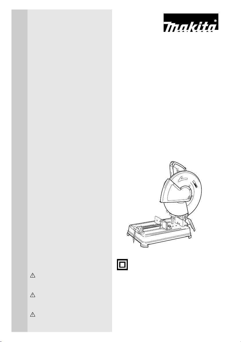
Portable Cut-Off
Tronçonneuse portative
Tronzadora de Metal
2414NB
003753
DOUBLE INSULATION
DOUBLE ISOLATION
DOBLE AISLAMIENTO
WARNING:
For your personal safety, READ and UNDERSTAND before using.
SAVE THESE INSTRUCTIONS FOR FUTURE REFERENCE.
AVERTISSEMENT:
Pour votre propre sécurité, prière de lire attentivement avant l’utilisation.
GARDER CES INSTRUCTIONS POUR RÉFÉRENCE ULTÉRIEURE.
ADVERTENCIA:
Para su seguridad personal, LEA DETENIDAMENTE este manual antes de usar la herramienta.
GUARDE ESTAS INSTRUCCIONES PARA FUTURA REFERENCIA.
Page 2

ENGLISH
SPECIFICATIONS
Model 2414NB
Wheel diameter 355 mm (14”)
Hole diameter 25.4 mm (1”)
No load speed (RPM) 3,800 /min.
Dimensions (L x W x H) 500 mm x 280 mm x 600 mm (19-3/4” x 11” x 23-5/8”)
Net weight 16.4kg (36.2 lbs)
• Due to our continuing programme of research and development, the specifications herein are subject to change
without notice.
• Note: Specifications may differ from country to country.
For Your Own Safety Read Instruction Manual Before Operating Tool
Save it for future reference
GENERAL SAFETY PRECAUTIONS
USA007-2
(For All Tools)
1. KNOW YOUR POWER TOOL. Read the owner’s
manual carefully. Learn the tool’s applications
and limitations, as well as the specific potential
hazards peculiar to it.
2. KEEP GUARDS IN PLACE and in working order.
3. REMOVE ADJUSTING KEYS AND WRENCHES.
Form habit of checking to see that keys and
adjusting wrenches are removed from tool
before turning it on.
4. KEEP WORK AREA CLEAN. Cluttered areas and
benches invite accidents.
5. DON’T USE IN DANGEROUS ENVIRONMENT.
Don’t use power tools in damp or wet locations,
or expose them to rain. Keep work area well
lighted. Don’t use tool in presence of flammable
liquids or gases.
6. KEEP CHILDREN AWAY. All visitors should be
kept safe distance from work area.
7. MAKE WORKSHOP KID PROOF with padlocks,
master switches, or by removing starter keys.
8. DON’T FORCE TOOL. It will do the job better and
safer at the rate for which it was designed.
9. USE RIGHT TOOL. Don’t force tool or attachment
to do a job for which it was not designed.
10. WEAR PROPER APPAREL. Do not wear loose
clothing, gloves, neckties, rings, bracelets, or
other jewelry which may get caught in moving
parts. Nonslip footwear is recommended. Wear
protective hair covering to contain long hair.
11. ALWAYS USE SAFETY GLASSES. Also use face
or dust mask if cutting operation is dusty. Everyday eyeglasses only have impact resistant
lenses, they are NOT safety glasses.
12. SECURE WORK. Use clamps or a vise to hold
work when practical. It’s safer than using your
hand and it frees both hands to operate tool.
13. DON’T OVERREACH. Keep proper footing and
balance at all times.
14. MAINTAIN TOOLS WITH CARE. Keep tools sharp
and clean for best and safest performance. Follow instructions for lubricating and changing
accessories.
15. DISCONNECT TOOLS before servicing; when
changing accessories such as blades, bits, cutters, and the like.
16. REDUCE THE RISK OF UNINTENTIONAL STARTING. Make sure switch is in off position before
plugging in.
17. USE RECOMMENDED ACCESSORIES. Consult
the owner’s manual for recommended accessories. The use of improper accessories may cause
risk of injury to persons.
18. NEVER STAND ON TOOL. Serious injury could
occur if the tool is tipped or if the cutting tool is
unintentionally contacted.
19. CHECK DAMAGED PARTS. Before further use of
the tool, a guard or other part that is damaged
should be carefully checked to determine that it
will operate properly and perform its intended
function - check for alignment of moving parts,
binding of moving parts, breakage of parts,
mounting, and any other conditions that may
affect its operation. A guard or other part that is
damaged should be properly repaired or
replaced.
20. DIRECTION OF FEED. Feed work into a blade or
cutter against the direction of rotation of the
blade or cutter only.
2
Page 3

21. NEVER LEAVE TOOL RUNNING UNATTENDED.
TURN POWER OFF. Don’t leave tool until it
comes to a complete stop.
22. REPLACEMENT PARTS. When servicing use
only identical replacement parts.
23. POLARIZED PLUGS. To reduce the risk of electric shock, this equipment has a polarized plug
(one blade is wider than the other). This plug will
fit in a polarized outlet only one way. If the plug
does not fit fully in the outlet, reverse the plug. If
it still does not fit, contact a qualified electrician
to install the proper outlet. Do not change the
plug in any way.
VOLTAGE WARNING: Before connecting the tool to a
power source (receptacle, outlet, etc.) be sure the volt-
age supplied is the same as that specified on the nameplate of the tool. A power source with voltage greater
than that specified for the tool can result in SERIOUS
INJURY to the user – as well as damage to the tool. If in
doubt, DO NOT PLUG IN THE TOOL. Using a power
source with voltage less than the nameplate rating is
harmful to the motor.
USE PROPER EXTENSION CORD: Make sure your
extension cord is in good condition. When using an
extension cord, be sure to use one heavy enough to
carry the current your product will draw. An undersized
cord will cause a drop in line voltage resulting in loss of
power and overheating. Table 1 shows the correct size to
use depending on cord length and nameplate ampere
rating. If in doubt, use the next heavier gage. The smaller
the gage number, the heavier the cord.
Table 1. Minimum gage for cord
Ampere Rating
Volts Total length of cord in feet
120 V 25 ft. 50 ft. 100 ft. 150 ft.
More Than Not More Than AWG
0 6 18 16 16 14
6 10 18161412
10 12 16 16 14 12
12 16 14 12 Not Recommended
SPECIFIC SAFETY RULES
USB078-1
DO NOT let comfort or familiarity with
product (gained from repeated use)
replace strict adherence to portable cutoff safety rules. If you use this tool
unsafely or incorrectly, you can suffer
serious personal injury.
1. Wear hearing protection during extended periods of operation.
2. Use only wheels having a maximum operating
speed at least as high as “No Load RPM”
marked on the tool’s nameplate. Use only fiberglass-reinforced cut-off wheels.
3. Check the wheel carefully for cracks or damage
before operation. Replace cracked or damaged
wheel immediately. Run the tool (with guard) at
no load for about a minute, keeping tool away
from others. If wheel is flawed, it will likely separate during this test.
4. Secure the wheel carefully.
5. Use only flanges specified for this tool.
6. Be careful not to damage the spindle, the flange
(especially the installing surface) or the bolt.
Damage to these parts could result in wheel
breakage.
7. Do not operate the tool without guards in place.
Check wheel guard for proper closing before
each use. Do not operate the tool if wheel guard
does not move freely and close instantly. Never
clamp or tie the wheel guard into the open position.
8. Hold the handle firmly.
9. Keep hands away from rotating parts.
10. Make sure the wheel is not contacting the workpiece before the switch is turned on.
11. Before using the tool on an actual workpiece, let
it run for a while. Watch for vibration or wobbling
that could indicate poor installation or a poorly
balanced wheel.
12. Watch out for flying sparks when operating.
They can cause injury or ignite combustible
materials.
13. Remove material debris from the area that might
be ignited by sparks. Be sure that others are not
in the path of the sparks. Keep a proper ,
charged extinguisher closely available.
14. Use the cutting edge of the wheel only. Never
use side surface.
15. Do not attempt to keep the trigger in the ON
position.
16. If the wheel stops during operation, makes an
odd noise or begins to vibrate, switch off the tool
immediately.
3
Page 4
17. Turn off the tool and wait for the wheel to stop
before moving workpiece or changing settings.
18. Do not touch the workpiece immediately after
operation; it is extremely hot and could burn
your skin.
19. Store wheels in a dry location only.
SAVE THESE INSTRUCTIONS
WARNING:
MISUSE or failure to follow the safety
rules stated in this instruction manual
may cause serious personal injury.
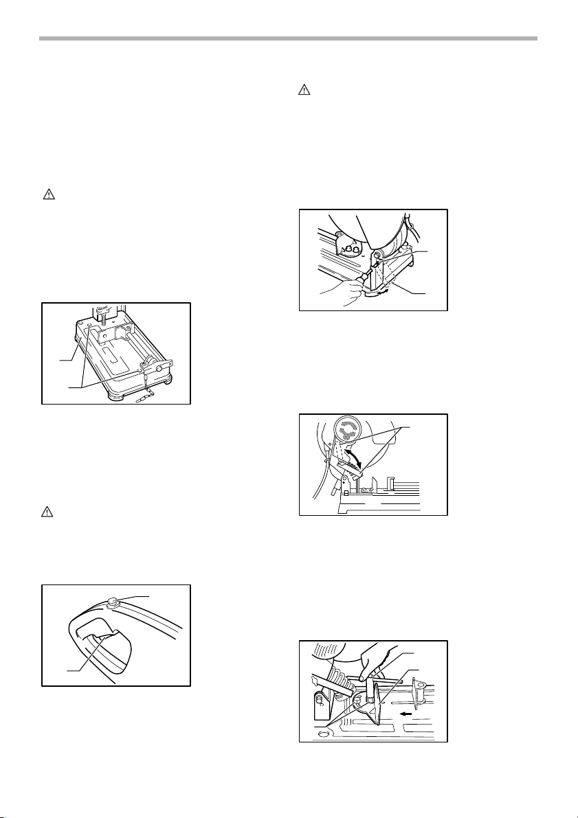
INSTALLATION
Securing cut-off
1
2
This tool should be bolted with two bolts to a level and
stable surface using the bolt holes provided in the tool’s
base. This will help prevent tipping and possible personal
injury.
003800
1. Base
2. Bolt holes
FUNCTIONAL DESCRIPTION
CAUTION:
• Before plugging in the tool, always check to see
that the switch trigger actuates properly and returns
to the “OFF” position when released.
To prevent the switch trigger from being accidentally
pulled, a lock-off button is provided.
To start the tool, depress the lock-off button and pull the
switch trigger. Release the switch trigger to stop.
Spark guard
The spark guard is factory-installed with its lower edge
contacting the base. Operating the tool in this position
will cause many sparks to fly around. Loosen the screw
and adjust the spark guard to a position at which minimum sparks will fly around.
Stopper plate
(B)
(A)
003756
1. Screw
2. Spark guard
1
2
003757
1
1. Stopper plate
CAUTION:
• Always be sure that the tool is switched off and
unplugged before adjusting or checking function on
the tool.
Switch action
2
003754
1
1. Lock-off button
2. Switch trigger
The stopper plate prevents the cut-off wheel from contacting the workbench or floor. When a new wheel is
installed, set the stopper plate to position (A). When the
wheel wears down to the extent that the lower portion of
the workpiece is left uncut, set the stopper plate to position (B) to allow increased cutting capacity with a worn
down wheel.
Interval between vise and guide plate
4
003758
1
2
3
1. Socket wrench
2. Guide plate
3. Move
4. Hex bolts
4
Page 5
The original spacing or interval between the vise and the
guide plate is 0 - 170 mm (0 - 6-11/16”). If your work
requires wider spacing or interval, proceed as follows to
change the spacing or interval.
Remove the two hex bolts which secure the guide plate.
Move the guide plate as shown in the figure and secure it
using the hex bolts. The following interval settings are
possible:
35 - 205 mm (1-3/8” - 8-1/16”)
70 - 240 mm (2-3/4” - 9-7/16”)
003759
CAUTION:
• Remember that narrow workpieces may not be
secured safely when using the two, wider interval
settings.
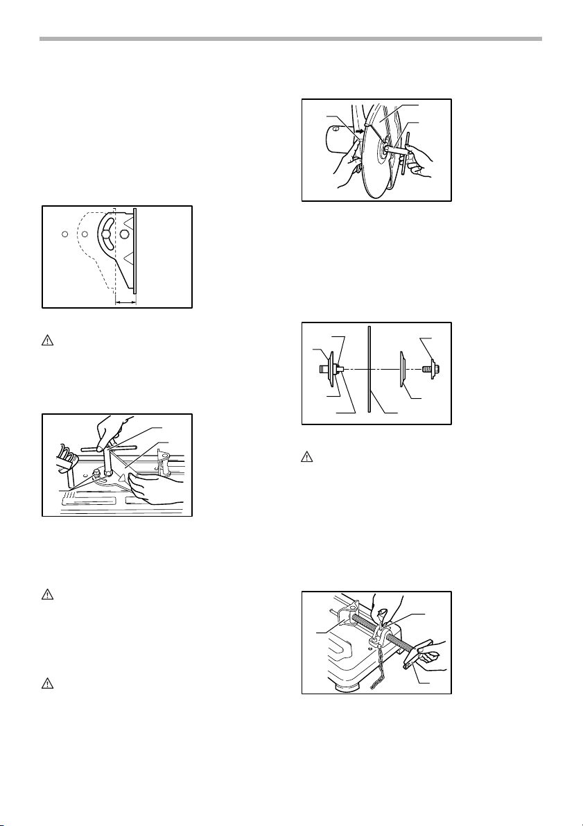
Setting for desired cutting angle
003760
1
2
1. Socket wrench
2. Guide plate
3. Hex bolts
3
To change the cutting angle, loosen the two hex bolts
which secure the guide plate. Move the guide plate to the
desired angle (0° - 45°) and tighten the hex bolts
securely.
CAUTION:
• Never perform miter cuts when the guide plate is
set at the 35 - 205 mm (1-3/8” - 8-1/16”) or 70 - 240
mm (2-3/4” - 9-7/16”) position.
Removing or installing cut-off wheel
1
003761
2
3
1. Shaft lock
2. Safety guard
3. Socket wrench
To remove the wheel, raise the safety guard. Press the
shaft lock so that the wheel cannot revolve and use the
socket wrench to loosen the hex bolt by turning it counterclockwise. Then remove the hex bolt, outer flange and
wheel. (Note: Do not remove the inner flange, ring and Oring.)
To install the wheel, follow the removal procedures in
reverse.
1
2
003762
7
1. O-ring
2. Inner flange
3. Ring
4. Spindle
5. Cut-off wheel
3
45
6
6. Outer flange
7. Hex bolt
CAUTION:
• Be sure to tighten the hex bolt securely. Insufficient
tightening of the hex bolt may result in severe injury.
Use the socket wrench provided to help assure
proper tightening.
• Always use only the proper inner and outer flanges
which are provided with this tool.
• Always lower the safety guard after replacing the
wheel.
Securing workpiece
003763
1. Vise plate
2. Vise nut
2
1
3. Vise handle
ASSEMBLY
CAUTION:
• Always be sure that the tool is switched off and
unplugged before carrying out any work on the tool.
3
By turning the vise handle counterclockwise and then
flipping the vise nut to the left, the vise is released from
the shaft threads and can be moved rapidly in and out. To
grip workpieces, push the vise handle until the vise plate
5
Page 6
contacts the workpiece. Flip the vise nut to the right and
then turn the vise handle clockwise to securely retain the
workpiece.
CAUTION:
• Always set the vise nut to the right fully when
securing the workpiece. Failure to do so may result
in insufficient securing of the workpiece. This could
cause the workpiece to be ejected or cause a
dangerous breakage of the wheel.
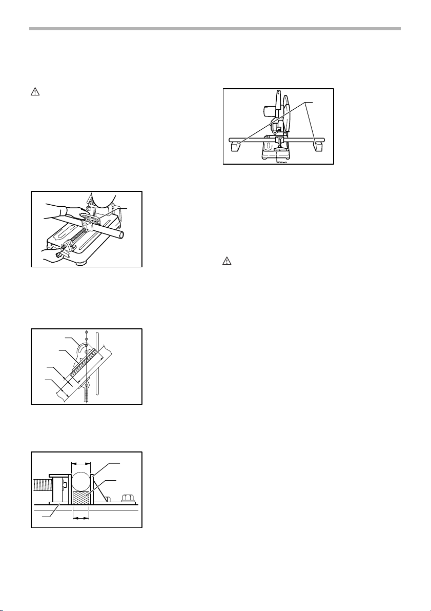
When the cut-off wheel has worn down considerably, use
a spacer block of sturdy, non-flammable material behind
the workpiece as shown in the figure. You can more efficiently utilize the worn wheel by using the mid point on
the periphery of the wheel to cut the workpiece.
003764
1. Spacer block
1
When cutting workpieces over 65 mm (2-9/16”) wide at
an angle, attach a straight piece of wood (spacer) over
190 mm (7-1/2”) long x 45 mm (1-3/4”) wide to the guide
plate as shown in the figure. Attach this spacer with
screws through the holes in the guide plate.
1
2
3
5
4
003765
1. Guide plate
2. Straight piece of
wood (Spacer)
3. Over 45 mm
(1-3/4”) long
4. Over 65 mm
(2-9/16”) long
5. Over 190 mm
(7-1/2”) long
Long workpieces must be supported by blocks of nonflammable material on either side so that it will be level
with the base top.
003767
1. Blocks
1
OPERATION
Hold the handle firmly. Switch on the tool and wait until
the wheel attains full speed before lowering gently into
the cut. When the wheel contacts the workpiece, gradually bear down on the handle to perform the cut. When
the cut is completed, switch off the tool and WAIT UNTIL
THE WHEEL HAS COME TO A COMPLETE STOP
before returning the handle to the fully elevated position.
CAUTION:
• Proper handle pressure during cutting and
maximum cutting efficiency can be determined by
the amount of sparks that is produced while cutting.
Your pressure on the handle should be adjusted to
produce the maximum amount of sparks. Do not
force the cut by applying excessive pressure on the
handle. Reduced cutting efficiency, premature
wheel wear, as well as, possible damage to the tool,
cut-off wheel or workpiece may result.
Cutting capacity
Max. cutting capacity varies depending upon the cutting
angle and workpiece shape. Applicable wheel diameter:
355 mm (14”)
If you use a spacer block which is slightly narrower than
the workpiece as shown in the figure, you can also utilize
the wheel economically.
1
003766
2
3
1. Diameter of
workpiece
2. Guide plate
3. Spacer block
4. Width of spacer
block
5
4
5. Vise
6
Page 7

Cutting
angle
Workpiece
shape
90˚
45˚
115mm (4-1/2”) 119mm (4-11/16”)
115mm (4-1/2”) 106 mm (4-3/16”)
115mm × 130 mm (4-1/2” × 5-1/8”)
102 mm × 194 mm (4” × 7-5/8”)
70 mm × 233 mm (2-3/4” × 9-1/8”)
115 mm × 103 mm (4-1/2” × 4-1/16”)
003787
137 mm (5-3/8”)
100 mm (3-15/16”)
Carrying tool
Fold down the tool head to the position where you can
attach the chain to the hook on the handle.
003768
MAINTENANCE
CAUTION:
• Always be sure that the tool is switched off and
unplugged before attempting to perform inspection
or maintenance.
Replacing carbon brushes
001145
1. Limit mark
1
Use a screwdriver to remove the brush holder caps. Take
out the worn carbon brushes, insert the new ones and
secure the brush holder caps.
To maintain product SAFETY and RELIABILITY, repairs,
any other maintenance or adjustment should be performed by Makita Authorized or Factory Service Centers,
always using Makita replacement parts.
003769
1
2
1. Screwdriver
2. Brush holder
cap
ACCESSORIES
CAUTION:
• These accessories or attachments are
recommended for use with your Makita tool
specified in this manual. The use of any other
accessories or attachments might present a risk of
injury to persons. Only use accessory or
attachment for its stated purpose.
If you need any assistance for more details regarding
these accessories, ask your local Makita Service Center.
• Abrasive cut-off wheels
• Socket wrench 17
Remove and check the carbon brushes regularly.
Replace when they wear down to the limit mark. Keep
the carbon brushes clean and free to slip in the holders.
Both carbon brushes should be replaced at the same
time. Use only identical carbon brushes.
7
Page 8

MAKITA LIMITED ONE YEAR WARRANTY
EN0006-1
Warranty Policy
Every Makita tool is thoroughly inspected and tested
before leaving the factory. It is warranted to be free of
defects from workmanship and materials for the period of
ONE YEAR from the date of original purchase. Should
any trouble develop during this one year period, return
the COMPLETE tool, freight prepaid, to one of Makita’s
Factory or Authorized Service Centers. If inspection
shows the trouble is caused by defective workmanship or
material, Makita will repair (or at our option, replace)
without charge.
This Warranty does not apply where:
• repairs have been made or attempted by others:
• repairs are required because of normal wear and
tear:
• the tool has been abused, misused or improperly
maintained:
• alterations have been made to the tool.
IN NO EVENT SHALL MAKITA BE LIABLE FOR ANY
INDIRECT, INCIDENTAL OR CONSEQUENTIAL DAMAGES FROM THE SALE OR USE OF THE PRODUCT.
THIS DISCLAIMER APPLIES BOTH DURING AND
AFTER THE TERM OF THIS WARRANTY.
MAKITA DISCLAIMS LIABILITY FOR ANY IMPLIED
WARRANTIES, INCLUDING IMPLIED WARRANTIES
OF “MERCHANTABILITY” AND “FITNESS FOR A SPECIFIC PURPOSE,” AFTER THE ONE YEAR TERM OF
THIS WARRANTY.
This Warranty gives you specific legal rights, and you
may also have other rights which vary from state to state.
Some states do not allow the exclusion or limitation of
incidental or consequential damages, so the above limitation or exclusion may not apply to you. Some states do
not allow limitation on how long an implied warranty lasts,
so the above limitation may not apply to you.
8
Page 9

FRANÇAIS
SPÉCIFICATIONS
Modèle 2414NB
Diamètre de la meule 355 mm (14”)
Diamètre de l’orifice 25.4 mm (1”)
Vitesse à vide (T/MIN) 3,800 /min.
Dimensions (L x L x H) 500 mm x 280 mm x 600 mm (19-3/4” x 11” x 23-5/8”)
Poids net 16.4kg (36.2 lbs)
• Le fabricant se réserve le droit de modifier sans avertissement les spécifications.
• Note: Les spécifications peuvent varier selon les pays.
Pour votre propre sécurité, veuillez
lire le manuel d’instructions avant
d’utiliser l’outil Conservez-le pour
référence ultérieure
CONSIGNES GÉNÉRALES DE
SÉCURITÉ
USA007-2
(Pour TOUS LES OUTILS)
1. VOUS DEVEZ CONNAÎTRE VOTRE OUTIL
ÉLECTRIQUE. Lisez attentivement le manuel
d’instructions. Familiarisez-vous avec les
applications et limites de l’outil, ainsi qu’avec
les risques potentiels qui lui sont spécifiques.
2. MAINTENEZ LES PROTECTEURS EN PLACE et
en bon état de fonctionnement.
3. RETIREZ LES CLÉS DE RÉGLAGE ET LES CLÉS.
Prenez l’habitude de vous assurer que les clés et
clés de réglage ont été retirées de l’outil avant de
le mettre sous tension.
4. MAINTENEZ L’AIRE DE TRAVAIL PROPRE. Les
aires de travail et les établis encombrés ouvrent
la porte aux accidents.
5. ÉVITEZ L’UTILISATION DANS UN
ENVIRONNEMENT DANGEREUX. N’utilisez pas
les outils électriques dans les endroits humides
ou mouillés, et ne les exposez pas à la pluie.
Maintenez un éclairage adéquat dans l’aire de
travail. N’utilisez pas l’outil en présence de
liquides ou gaz inflammables.
6. MAINTENEZ LES ENFANTS À L’ÉCART. Toute
autre personne que l’utilisateur de l’outil doit se
tenir à une distance sûre de l’aire de travail.
7. FAITES EN SORTE QUE L’ATELIER SOIT SANS
DANGER POUR LES ENFANTS, en y posant des
cadenas, un interrupteur principal, ou en retirant
des équipements leurs clés de démarrage.
8. NE FORCEZ PAS L’OUTIL. Il effectuera un travail
de meilleure qualité et plus sûr s’il est utilisé au
régime pour lequel il a été conçu.
9. UTILISEZ LE BON OUTIL. Ne forcez pas un outil
ou accessoire à effectuer un travail pour lequel il
n’a pas été conçu.
10. PORTEZ DES VÊTEMENTS ADÉQUATS. Ne
portez ni vêtements ni gants amples, ni cravate,
anneaux, bracelets ou autres bijoux
susceptibles d’être happés par les pièces
mobiles de l’outil. Le port de chaussures
antidérapantes est recommandé. Portez un filet
de protection pour envelopper les cheveux
longs.
11. PORTEZ TOUJOURS DES LUNETTES DE
PROTECTION. Si le travail de coupe dégage de la
poussière, portez également un écran facial ou
un masque antipoussières. Les lunettes
ordinaires ne sont munies que de lentilles
résistances aux chocs ; elles ne constituent PAS
des lunettes de protection.
12. FIXEZ BIEN LA PIÈCE. Lorsque cela est
possible, fixez la pièce à travailler à l’aide de
dispositifs de serrage ou d’un étau. Cela est plus
sécuritaire que l’utilisation de la main et libère
les deux mains pour le maniement de l’outil.
13. MAINTENEZ UNE BONNE POSITION. Assurezvous d’une bonne prise au sol et d’une bonne
position d’équilibre en tout temps.
14. PRENEZ SOIN DES OUTILS. Maintenez les outils
bien aiguisés et propres pour assurer une
performance sécuritaire et optimale. Suivez les
instructions de lubrification et de changement
des accessoires.
15. DÉBRANCHEZ LES OUTILS avant tout travail de
réparation ou avant de changer les accessoires
tels que lames, embouts/forets/fraises et
couteaux.
16. RÉDUISEZ LES RISQUES DE MISE EN MARCHE
ACCIDENTELLE. Assurez-vous que
l’interrupteur est en position d’arrêt avant de
brancher l’outil.
9
Page 10

17. UTILISEZ LES ACCESSOIRES RECOMMANDÉS.
Consultez le manuel de l’utilisateur pour savoir
quels sont les accessoires recommandés.
L’utilisation d’accessoires non adéquats peut
comporter un risque de blessure.
18. NE VOUS APPUYEZ JAMAIS SUR L’OUTIL. Une
blessure grave peut survenir si l’outil bascule ou
si vous touchez accidentellement l’outil
tranchant.
19. VÉRIFIEZ S’IL Y A DES PIÈCES
ENDOMMAGÉES. Avant d’utiliser l’outil, tout
protecteur ou dispositif endommagé doit être
vérifié soigneusement afin de s’assurer qu’il
fonctionne adéquatement et peut remplir la
fonction pour laquelle il est conçu. Vérifiez si les
pièces mobiles sont bien alignées et bien fixées,
vérifiez la présence de pièces brisées, vérifiez
que l’outil est bien monté et assurez-vous que
rien ne peut entraver son bon fonctionnement.
Un protecteur ou tout autre dispositif
endommagé doit être adéquatement réparé ou
remplacé.
20. SENS D’ALIMENTATION. N’alimentez la lame ou
l’outil tranchant avec la pièce à travailler que
dans le sens opposé à celui de la progression de
la lame ou de l’outil tranchant.
21. NE LAISSEZ JAMAIS SANS SURVEILLANCE UN
OUTIL EN MARCHE. COUPEZ LE CONTACT.
Attendez que l’outil se soit complètement arrêté
avant de le quitter.
22. PIÈCES DE RECHANGE. Seules des pièces de
rechange identiques doivent être utilisées lors
des réparations.
23. FICHES POLARISÉES. Pour réduire les risques
de choc électrique, cet appareil est muni d’une
fiche polarisée (une des broches est plus large
que l’autre). Cette fiche ne peut être insérée
dans une prise polarisée que dans un seul sens.
Si la fiche ne s’insère pas à fond dans la prise,
insérez-la en sens inverse. Si elle ne s’insère
toujours pas à fond, contactez un technicien
qualifié pour faire installer une prise appropriée.
N’apportez aucune modification à la fiche.
MISE EN GARDE RELATIVE À LA TENSION: Avant de
brancher l’outil sur une source d’alimentation (prise ou
autre dispositif), assurez-vous que la tension du circuit
correspond à celle qui est spécifiée sur la plaque
signalétique de l’outil. L’utilisation d’une source
d’alimentation dont la tension est supérieure à celle
spécifiée pour l’outil peut entraîner l’utilisateur à une
GRAVE BLESSURE et endommager l’outil. En cas de
doute, NE BRANCHEZ PAS L’OUTIL. L’utilisation d’une
source d’alimentation dont la tension est inférieure à la
valeur indiquée sur la plaque signalétique endommagera
le moteur.
UTLISEZ UN CORDON PROLONGATEUR ADÉQUAT.
Assurez-vous que le cordon prolongateur est en bon
état. Lors de l’utilisation d’un cordon prolongateur,
utilisez sans faute un cordon assez gros pour conduire le
courant que le produit nécessite. Un cordon trop petit
provoquera une baisse de tension de secteur, résultant
en une perte de puissance et une surchauffe. Le Tableau
1 indique la dimension appropriée de cordon selon sa
longueur et selon l’intensité nominale indiquée sur la
plaque signalétique. En cas de doute sur un cordon
donné, utilisez le cordon suivant (plus gros). Plus le
numéro de gabarit indiqué est petit, plus le cordon est
gros.
Tableau 1. Gabarit minimum du cordon
Intensité nominale
Volts Longueur totale du cordon en pieds
120 V 25 ft. 50 ft. 100 ft. 150 ft.
Plus de Pas plus de Calibre américain des fils
0 6 18 16 16 14
6 10 18161412
10 12 16 16 14 12
12 16 14 12 Non recommandé
CONSIGNES DE SÉCURITÉ
SPÉCIFIQUES
USB078-1
NE vous laissez PAS tromper (au fil d’une
utilisation répétée) par un sentiment
d’aisance et de familiarité avec le
produit, en négligeant le respect
rigoureux des consignes de sécurité qui
accompagnent la scie circulaire à
tronçonner portable. Si vous n’utilisez
pas cet outil de façon sûre et adéquate,
vous courez un risque de blessure grave.
1. Portez une protection d’oreilles lors des travaux
de longue durée.
2. Utilisez uniquement des meules dont la vitesse
de rotation maximale est au moins égale à la
vitesse maximale de fonctionnement à vide
(« No Load RPM ») indiquée sur la plaque
10
Page 11

signalétique de l’outil. Utilisez exclusivement
des meules à tronçonner renforcées de fibre de
verre.
3. Avant l’utilisation, vérifiez toujours
soigneusement l’absence de fissures ou de
dommages sur la meule. Remplacez
immédiatement toute meule fissurée ou
endommagée. Faites tourner l’outil à vide (avec
son protecteur) pendant environ 1 minute, en le
maintenant à l’écart de toute personne présente.
Si la meule est défectueuse, elle se détachera
probablement pendant ce test.
4. Fixez fermement la meule.
5. Utilisez exclusivement les flasques spécifiés
pour cet outil.
6. Prenez garde d’endommager l’axe, le flasque
(tout particulièrement la surface par laquelle il
s’installe) ou le boulon. La meule risque de
casser si ces pièces sont endommagées.
7. N’utilisez jamais l’outil si les protecteurs ne sont
pas bien en place. Avant chaque utilisation,
assurez-vous que le protecteur de meule se
referme bien. N’utilisez pas l’outil si le protecteur
de meule ne se déplace pas librement et ne se
referme pas sur la meule instantanément.
N’immobilisez ou ne fixez jamais le carter de
meule en position ouverte.
8. Tenez la poignée fermement.
9. Gardez les mains éloignées des pièces en
rotation.
10. Assurez-vous que la meule n’entre pas en
contact avec la pièce avant de mettre l’outil sous
tension.
11. Avant de commencer l’utilisation de l’outil,
faites-le tourner un instant à vide. Soyez attentif
à toute vibration ou sautillement pouvant
indiquer que la meule n’est pas bien installée ou
qu’elle est mal équilibrée.
12. Prenez garde aux étincelles pendant l’utilisation.
Elles peuvent causer des blessures ou
enflammer les matériaux combustibles.
13. Retirez de la zone de travail tout matériau
pouvant être enflammé par les étincelles.
Assurez-vous que personne ne se trouve là où
l’outil lance des étincelles. Gardez toujours un
extincteur propre et plein à portée de la main.
14. Utilisez exclusivement le tranchant de la meule.
N’utilisez jamais sa face latérale.
15. N’essayez pas de verrouiller la gâchette en
position de marche.
16. Si la meule s’arrête pendant la coupe, émet un
bruit anormal ou se met à vibrer, éteignez
immédiatement l’outil.
17. Éteignez l’outil et attendez l’arrêt de la meule
avant de déplacer la pièce à travailler ou de
modifier les réglages.
18. Ne touchez jamais la pièce juste après la coupe ;
elle est alors extrêmement chaude et risquerait
de vous brûler.
19. Rangez toujours les meules dans un endroit sec.
CONSERVEZ CES
INSTRUCTIONS
AVERTISSEMENT:
LA MAUVAISE UTILISATION de l’outil ou
l’ignorance des consignes de sécurité du
présent manuel d’instructions peuvent
entraîner une grave blessure.
Pose
Protection contre les coupures
1
2
Cet outil doit être fixé à une surface plane et stable au
moyen de boulons insérés dans les orifices prévus à cet
effet sur la base de l’outil. Cela aidera à prévenir les
risques de basculement et de blessure.
003800
1. Base
2. Orifices à
boulon
DESCRIPTION DU
FONCTIONNEMENT
ATTENTION:
• Assurez-vous toujours que l’outil est hors tension et
débranché avant de l’ajuster ou de vérifier son
fonctionnement.
Interrupteur
2
003754
1
1. Bouton de
sécurité
2. Gâchette
11
Page 12

ATTENTION:
• Avant de brancher l’outil, assurez-vous toujours
que la gâchette fonctionne correctement et revient
en position d’arrêt une fois relâchée.
Un bouton de sécurité est fourni pour prévenir la
pression accidentelle sur la gâchette.
Pour mettre l ’outil en marche, enfoncez le bouton de
sécurité puis appuyez sur la gâchette. Pour l’arrêter,
relâchez la gâchette.
Pare-étincelles
003756
1. Vis
2. Pare-étincelles
1
2
Le pare-étincelles est installé en usine avec le bord
inférieur en contact avec la base. L’outil projettera
beaucoup d’étincelles si vous l’utilisez avec la pareétincelles dans cette position. Desserrez la vis et ajustez
le pare-étincelles sur la position qui permet de réduire le
plus possible la quantité d’étincelles projetées.
Limiteur de course
(B)
(A)
003757
1
1. Limiteur de
course
Le limiteur de course a pour but d’empêcher le disque à
tronçonner de toucher l’établi ou la table. Quand vous
installez un disque neuf, fixez le limiteur de course à la
position (A). Quand le disque s’use au point de ne plus
couper la section inférieure de la pièce, fixez le limiteur
de course à la position (B) de façon à accroître la
capacité de coupe avec un disque usé.
Intervalle entre le talon et la butée orientable
003758
1. Clé à douille
1
2. Butée orientable
2
3. Reculer
4. Boulons
hexagonaux
3
4
La course initiale du talon de l’étau est de 0 à 170 mm (0
- 6-11/16”). Si votre travail réclame un débattement plus
important procédez comme suit.
Retirez les deux boulons hexagonaux de fixation de la
butée orientable, puis reculez celle-ci sur sa nouvelle
position et refixez-la avec les boulons hexagonaux. Vous
avez le choix entre les courses suivantes:
35 - 205 mm (1-3/8” - 8-1/16”)
70 - 240 mm (2-3/4” - 9-7/16”)
003759
ATTENTION:
• Ces deux réglages sont destinés à des pièces de
dimensions importantes et ne conviennent pas à
des pièces de petite taille.
Réglage de l’angle de coupe
003760
1. Clé à douille
1
2. Butée orientable
2
3. Boulons
hexagonaux
3
Pour régler l’angle de coupe, desserrez les deux boulons
hexagonaux de fixation de la butée orientable. Amenez
la butée orientable sur l’angle voulu (0° à 45°) et serrez
les boulons hexagonaux à fond.
ATTENTION:
• Ne jamais effectuer de coupes d’onglet lorsque la
butée orientable est réglée en position 35 - 205 mm
(1-3/8” - 8-1/16”) ou 70 - 240 mm (2-3/4” - 9-7/16”).
12
Page 13

ASSEMBLAGE
ATTENTION:
• Avant d’effectuer toute intervention sur l’outil,
assurez-vous toujours qu’il est hors tension et
débranché.
Retrait ou pose du disque à tronçonner
1
Pour retirer le disque, soulevez le carter de sécurité.
Appuyez sur le blocage de l’arbre de sorte que le disque
ne puisse pas tourner et utilisez la clé à douille pour
desserrer le boulon hexagonal en le tournant dans le
sens inverse des aiguilles d’une montre. Retirez ensuite
le boulon hexagonal, le flasque extérieur et le disque.
(Remarque : Ne pas retirer le flasque intérieur, l’anneau
et le joint torique.)
Pour installer le disque, reprenez ces opérations en ordre
inverse.
1
2
3
45
003761
2
3
003762
7
6
1. Blocage de
l’arbre
2. Carter de
sécurité
3. Clé à douille
1. Joint torique
2. Flasque
intérieur
3. Anneau
4. Arbre
5. Disques à
tronçonner
6. Flasque
extérieur
7. Boulon
hexagonal
Immobilisation de la pièce
1
003763
1. Plaque de l’étau
2. Écrou de l’étau
2
3. Poignée de
l’étau
3
Vous pouvez dégager l’étau des filages de l’arbre et le
déplacer rapidement vers l’intérieur et l’extérieur en
tournant la poignée de l’étau dans le sens inverse des
aiguilles d’une montre et en basculant l’écrou de l’étau
vers la gauche. Pour serrer la pièce à travailler, poussez
sur la poignée de l’étau jusqu’à ce que la plaque de
l’étau entre en contact avec la pièce. Basculez l’écrou de
l’étau vers la droite puis tournez la poignée de l’étau
dans le sens des aiguilles d’une montre pour immobiliser
solidement la pièce à travailler.
ATTENTION:
• Lorsque vous immobilisez la pièce, tournez
toujours l’écrou de l’étau complètement vers la
droite. Sinon, la pièce risque de ne pas être
solidement immobilisée. Cela peut causer une
situation dangereuse si la pièce à travailler est
éjectée ou si le disque se casse.
Lorsque l’usure a déjà notablement diminué le diamètre
du disque, vous devez veiller à ce que ce soit toujours la
partie de sa périphérie située à l’aplomb de son axe qui
serve à la coupe : au besoin, intercalez dans l’étau
derrière la pièce un martyr (non inflammable), comme
indiqué sur la figure.
003764
1
1. Cale
d’espacement
ATTENTION:
• Serrez bien le boulon hexagonal à fond. S’il est mal
serré, il peut être la cause de graves blessures.
Pour obtenir un serrage satisfaisant, servez-vous
de la clé à douille fournie avec l’outil.
• N’utilisez comme flasques intérieur et extérieur que
les pièces livrées avec l’outil.
• Toujours rabaisser le carter de sécurité après avoir
remplacé le disque.
Lorsque vous coupez en angle des pièces d’une largeur
supérieure à 65 mm (2-9/16”), fixez une pièce de bois
rectiligne (une entretoise) d’une longueur supérieure à
190 mm (7-1/2”) et d’une largeur de 45 mm (1-3/4”) sur la
butée orientable, telle qu’indiqué sur l’illustration. Fixez
cette entretoise en insérant des vis dans les orifices de la
butée orientable.
13
Page 14

003765
1
2
3
5
4
1. Butée orientable
2. Pièce de bois
rectiligne
(une entretoise)
3. Longueur
supérieure à
45 mm (1-3/4”)
4. Longueur
supérieure à
65 mm (2-9/16”)
5. Longueur
supérieure à
190 mm (7-1/2”)
L’utilisation d’une cale d’espacement légèrement plus
étroite que la pièce à travailler, tel qu’indiqué sur
l’illustration, permet d’utiliser le disque de manière
économique.
1
003766
1. Diamètre de
2
2. Butée orientable
3
3. Cale
pièce
d’espacement
4. Large du cale
d’espacement
5
4
5. Étau
Forme de
la pièce
Angle
d’attaque
90˚
45˚
115mm (4-1/2”) 119mm (4-11/16”)
115mm (4-1/2”) 106 mm (4-3/16”)
Les longues pièces à travailler doivent être soutenues de
chaque côté par des blocs en matériau ininflammable
placés au même niveau que le dessus de la base.
003767
1. Blocs
1
UTILISATION
Tenez la poignée fermement. Mettez l’outil sous tension
et attendez que le disque ait atteint sa pleine vitesse
avant de l’amener doucement en position de coupe.
Lorsque le disque arrive au contact de la pièce, pesez
progressivement sur la poignée pour effectuer le
tronçonnage. Dès que la pièce est complètement
tronçonnée, arrêtez l’outil et ATTENDEZ QUE L’OUTIL
SOIT ARRIVE A UN ARRET COMPLET avant de laisser
la poignée rejoindre sa position haute.
ATTENTION:
• Déterminez la pression sur la poignée et le
rendement maximum de tronçonnage en fonction
de la quantité d’étincelles produites par le disque.
Réglez votre pression sur la poignée de façon à
produire le maximum d’étincelles. Ne forcez pas la
coupe en appuyant trop fort sur la poignée : vous
n’obtiendriez plus qu’un rendement médiocre, avec
usure rapide du disque et le risque d’avarier l’outil
et le disque et d’abîmer la pièce.
Capacité de coupe
La capacité de coupe maximale dépend de l’angle
d’attaque et de la forme de la pièce. Les cotes cidessous correspondent à un disque ayant comme
caractéristiques: 355 mm (14”)
115mm × 130 mm (4-1/2” × 5-1/8”)
102 mm × 194 mm (4” × 7-5/8”)
70 mm × 233 mm (2-3/4” × 9-1/8”)
115 mm × 103 mm (4-1/2” × 4-1/16”)
137 mm (5-3/8”)
100 mm (3-15/16”)
003787
14
Page 15

Transport de l’outil
Abaissez le bras articulé jusqu’à pouvoir fixer la chaîne
au crochet de la poignée.
003768
ENTRETIEN
ATTENTION:
• Assurez-vous toujours que l’outil est hors tension et
débranché avant d’y effectuer tout travail
d’inspection ou d’entretien.
Remplacement des charbons
Retirez et vérifiez régulièrement les charbons.
Remplacez-les lorsqu’ils sont usés jusqu’au trait de limite
d’usure. Maintenez les charbons propres et en état de
glisser aisément dans les porte-charbon. Les deux
charbons doivent être remplacés en même temps.
N’utilisez que des charbons identiques.
Utilisez un tournevis pour retirer les bouchons de portecharbon. Enlevez les charbons usés, insérez-en de
nouveaux et revissez solidement les bouchons de portecharbon.
Pour maintenir la SÉCURITÉ et la FIABILITÉ du produit,
les réparations, tout autre travail d’entretien ou de
réglage doivent être effectués dans un centre de service
001145
1. Trait de limite
d’usure
1
003769
1. Tournevis
2. Bouchon de
1
2
porte-charbon
Makita agréé ou un centre de service de l’usine Makita,
exclusivement avec des pièces de rechange Makita.
ACCESSOIRES
ATTENTION:
• Ces accessoires ou pièces complémentaires sont
recommandés pour l’utilisation avec l’outil Makita
spécifié dans ce mode d’emploi. L’utilisation de tout
autre accessoire ou pièce complémentaire peut
comporter un risque de blessure. N’utilisez les
accessoires ou pièces qu’aux fins auxquelles ils ont
été conçus.
Si vous désirez obtenir plus de détails concernant ces
accessoires, veuillez contacter le centre de service
après-vente Makita le plus près.
• Disques à tronçonner abrasifs
• Clé à douille 17
GARANTIE LIMITÉE D’UN AN MAKITA
Politique de garantie
Chaque outil Makita est inspecté rigoureusement et testé
avant sa sortie d’usine. Nous garantissons qu’il sera
exempt de défaut de fabrication et de vice de matériau
pour une période d’UN AN à partir de la date de son
achat initial. Si un problème quelconque devait survenir
au cours de cette période d’un an, veuillez retourner
l’outil COMPLET, port payé, à une usine ou à un centre
de service après-vente Makita. Makita réparera l’outil
gratuitement (ou le remplacera, à sa discrétion) si un
défaut de fabrication ou un vice de matériau est
découvert lors de l’inspection.
Cette garantie ne s’applique pas dans les cas où :
• des réparations ont été effectuées ou tentées par
un tiers ;
• des réparations s’imposent suite à une usure
normale ;
• l’outil a été malmené, mal utilisé ou mal entretenu ;
• l’outil a subi des modifications.
MAKITA DÉCLINE TOUTE RESPONSABILITÉ POUR
TOUT DOMMAGE ACCESSOIRE OU INDIRECT LIÉ À
LA VENTE OU À L’UTILISATION DU PRODUIT. CET
AVIS DE NON-RESPONSABILITÉ S’APPLIQUE À LA
FOIS PENDANT ET APRÈS LA PÉRIODE COUVERTE
PAR CETTE GARANTIE.
MAKITA DÉCLINE TOUTE RESPONSABILITÉ QUANT
À TOUTE GARANTIE TACITE, INCLUANT LES
GARANTIES TACITES DE “QUALITÉ MARCHANDE” ET
“ADÉQUATION À UN USAGE PARTICULIER” APRÈS
LA PÉRIODE D’UN AN COUVERTE PAR CETTE
GARANTIE.
Cette garantie vous donne des droits spécifiques
reconnus par la loi, et possiblement d’autres droits, qui
varient d’un État à l’autre. Certains États ne permettant
pas l’exclusion ou la limitation des dommages
accessoires ou indirects, il se peut que la limitation ou
exclusion ci-dessus ne s’applique pas à vous. Certains
EN0006-1
15
Page 16

États ne permettant pas la limitation de la durée
d’application d’une garantie tacite, il se peut que la
limitation ci-dessus ne s’applique pas à vous.
16
Page 17

ESPAÑOL
ESPECIFICACIONES
Modelo 2414NB
Especificaciones eléctricas en México
Diámetro de disco 355 mm (14”)
Ángulo de bisel máximo 25,4 mm (1”)
Revoluciones por minuto (r.p.m.) 3 800 /min.
Dimensiones (L x A x A) 500 mm x 280 mm x 600 mm (19-3/4” x 11” x 23-5/8”)
Peso neto 16,4kg (36,2 lbs)
• Debido a un programa continuo de investigación y desarrollo, las especificaciones aquí dadas están sujetas a
cambios sin previo aviso.
• Nota: Las especificaciones pueden ser diferentes de país a país.
115 V 15 A 50/60 Hz
Por su propia seguridad lea el
Manual de Instrucciones Antes de
utilizar la herramienta Guarde las
instrucciones para referencia
futura
PRECAUCIONES DE SEGURIDAD
GENERALES
(PARA TODAS LAS HERRAMIENTAS)
1. CONOZCA SU HERRAMIENTA ELÉCTRICA. Lea
el manual del usuario atentamente. Conozca las
aplicaciones y limitaciones de la herramienta,
así como también los riesgos potenciales
específicos propios de ella.
2. NO QUITE LOS PROTECTORES y manténgalos
en buen estado de funcionamiento.
3. RETIRE LAS LLAVES DE AJUSTE Y DE
APRIETE. Adquiera el hábito de comprobar y ver
que las llaves de ajuste y de apriete estén
retiradas de la herramienta antes de ponerla en
marcha.
4. MANTENGA EL ÁREA DE TRABAJO LIMPIA. Las
áreas y bancos de trabajo atestados son una
invitación a accidentes.
5. NO LAS UTILICE EN AMBIENTES PELIGROSOS.
No utilice las herramientas eléctricas en lugares
húmedos o mojados, ni las exponga a la lluvia.
Mantenga el área de trabajo bien iluminada. No
utilice la herramienta en presencia de líquidos o
gases inflamables.
6. MANTENGA ALEJADOS A LOS NIÑOS. Todos
los visitantes deberán ser mantenidos a una
distancia segura del área de trabajo.
USA007-2
7. MANTENGA EL TALLER A PRUEBA DE NIÑOS
con candados, interruptores maestros, o
quitando las llaves de encendido.
8. NO FUERCE LA HERRAMIENTA. La herramienta
realizará la tarea mejor y de forma más segura a
la potencia para la que ha sido diseñada.
9. UTILICE LA HERRAMIENTA APROPIADA. No
fuerce la herramienta ni los accesorios
realizando con ellos un trabajo para el que no
han sido diseñados.
10. PÓNGASE INDUMENTARIA APROPIADA. No se
ponga ropa holgada, guantes, corbata, anillos,
pulseras, ni otro tipo de joyas que puedan
engancharse en las partes móviles. Se
recomienda utilizar calzado antideslizante.
Cúbrase el pelo para protegerlo si lo tiene largo.
11. UTILICE SIEMPRE GAFAS DE SEGURIDAD.
Utilice también máscara facial o contra el polvo
si la operación de corte es polvorienta. Las
gafas de uso diario para la vista sólo tienen
lentes que pueden proteger contra pequeños
impactos, NO son gafas de seguridad.
12. SUJETE LA PIEZA DE TRABAJO. Utilice
mordazas o un tornillo de banco para sujetar la
pieza de trabajo cuando resulte práctico. Es más
seguro que utilizar la mano y además dispondrá
de ambas manos para manejar la herramienta.
13. NO UTILICE LA HERRAMIENTA DONDE NO
ALCANCE. Mantenga los pies sobre suelo firme
y el equilibrio en todo momento.
14. DÉ MANTENIMIENTO A SUS HERRAMIENTAS.
Mantenga las herramientas afiladas y limpias
para obtener de ellas un mejor y más seguro
rendimiento. Siga las instrucciones para
lubricarlas y cambiar los accesorios.
15. DESCONECTE LAS HERRAMIENTAS antes de
hacerles el mantenimiento; cuando cambie
accesorios tales como discos, brocas, cuchillas,
y otros por el estilo.
17
Page 18

16. REDUZCA EL RIESGO DE PUESTAS EN
MARCHA INVOLUNTARIOS. Asegúrese de que el
interruptor esté en posición desactivada antes
de enchufar la herramienta.
17. UTILICE ACCESORIOS RECOMENDADOS.
Consulte el manual del propietario para ver los
accesorios recomendados. La utilización de
accesorios no apropiados podría ocasionar un
riesgo de heridas a personas.
18. NO SE PONGA NUNCA ENCIMA DE LA
HERRAMIENTA. Si tropieza con la herramienta o
si toca sin querer la hoja de corte podrá
ocasionarle graves heridas.
19. COMPRUEBE LAS PARTES DAÑADAS. Si un
protector u otra parte están dañados, antes de
seguir utilizando la herramienta deberá
verificarlos cuidadosamente para cerciorarse de
que van a funcionar debidamente y realizar la
función para la que han sido previstos –
compruebe la alineación de las partes móviles,
la sujeción de las partes móviles, si hay partes
rotas, el montaje y cualquier otra condición que
pueda afectar su operación. Un protector u otra
parte que estén dañados deberán ser reparados
debidamente o cambiados.
20. DIRECCIÓN DE AVANCE. Avance la pieza de
trabajo hacia el disco o cuchilla solamente a
contra dirección del giro del disco o cuchilla.
21. NUNCA DEJE LA HERRAMIENTA SOLA Y EN
MARCHA. DESCONECTE LA ALIMENTACIÓN.
No deje la herramienta hasta que se haya
detenido completamente.
22. PIEZAS DE REPUESTO. Cuando haga el servicio
a la herramienta, utilice solamente piezas de
repuesto idénticas.
Tabla 1. Calibre mínimo para el cable
Amperaje nominal
Más de
No más de
Más de
Voltios Longitud total del cable en metros
120 V~ 7,6 m 15,2 m 30,4 m 45,7 m
0 6 18 16 16 14
6 10 18161412
10 12 16 16 14 12
12 16 14 12 No se recomienda
23. CLAVIJAS POLARIZADAS Para reducir el riesgo
de descargas eléctricas, este equipo tiene una
clavija polarizada (un borne es más ancho que el
otro.) Esta clavija encajará en una toma de
corriente polarizada en un sentido solamente. Si
la clavija no encaja totalmente en la toma de
corriente, invierta la clavija. Si aún así no encaja,
póngase en contacto con un electricista
cualificado para que le instale la toma de
corriente apropiada. No cambie la clavija de
ninguna forma.
ADVERTENCIA SOBRE LA TENSIÓN: Antes de
conectar la herramienta a una toma de corriente
(enchufe, fuente de alimentación, etc.), asegúrese de
que la tensión suministrada es igual a la especificada en
la placa de características de la herramienta. Una toma
de corriente con una tensión mayor que la especificada
para la herramienta podrá resultar en HERIDAS
GRAVES al usuario -así como también daños a la
herramienta. Si no está seguro, NO ENCHUFE LA
HERRAMIENTA. La utilización de una toma de corriente
con una tensión menor a la nominal indicada en la placa
de características es dañina para el motor.
UTILICE CABLES DE EXTENSIÓN APROPIADOS:
Asegúrese de que su cable de extensión esté en buenas
condiciones. Cuando utilice un cable de extensión,
asegúrese de utilizar uno del calibre suficiente para
conducir la corriente que demande el producto. Un cable
de calibre inferior ocasionará una caída en la tensión de
línea que resultará en una pérdida de potencia y
recalentamiento. La Tabla 1 muestra el tamaño correcto
a utilizar dependiendo de la longitud del cable y el
amperaje nominal indicado en la placa de
características. Si no está seguro, utilice el siguiente
calibre más potente. Cuanto menor sea el número de
calibre, más potente será el cable.
Calibre del cable (AWG)
REGLAS ESPECÍFICAS DE
SEGURIDAD
USB078-1
NO permita que la comodidad o
familiaridad con el producto (a causa de
su uso frecuente) substituya el
cumplimiento estricto de las reglas de
seguridad de la cortadora portátil. Si
usted utiliza esta herramienta de modo
inseguro o incorrecto, puede sufrir
heridas graves.
1. Utilice protección auditiva cuando trabaje con
esta herramienta durante períodos prolongados.
18
Page 19

2. Utilice sólo ruedas que posean la máxima
velocidad operativa, como mínimo marcadas
con el rótulo del fabricante “Sin carga RPM”.
Sólo utilice ruedas de corte reforzadas con fibra
de vidrio.
3. Antes de poner la herramienta en
funcionamiento, asegúrese de que la rueda no
esté quebrada o dañada. Reemplace
inmediatamente la rueda cuando ésta se
encuentre rota o dañada. Ponga en marcha la
herramienta (con la protección) sin carga
durante aproximadamente un minuto, cuidando
de que esté fuera del alcance de otras personas.
Si la rueda estuviera defectuosa, es probable
que se separe de la herramienta durante la
prueba.
4. Asegure la rueda cuidadosamente.
5. Utilice solo las pestañas especificadas para esta
herramienta.
6. Tenga cuidado de no dañar el eje, la pestaña
(especialmente la superficie de instalación) o el
perno. Si se dañan estas partes se podría
romper la rueda.
7. No haga funcionar la herramienta si las
protecciones no están en su lugar. Asegúrese de
que la protección de la rueda se cierre
correctamente antes de cada uso. No utilice la
herramienta si la protección de la rueda no se
mueve libremente o no se cierra de manera
instantánea. Nunca fije o trabe la protección de
la rueda para ubicarla en la posición de abierto.
8. Sostenga firmemente la empuñadura.
9. Mantenga las manos alejadas de las partes
giratorias.
10. Asegúrese de que la rueda no esté en contacto
con la pieza antes de encender la herramienta.
11. Antes de utilizar la herramienta sobre una pieza
real, déjela funcionar un momento. Observe si
existe vibración u oscilaciones, lo que podría
indicar deficiencias en la instalación o en la
nivelación de la rueda.
12. Tenga cuidado con las chispas que se
desprenden mientras opera la herramienta.
Estas chispas pueden ocasionarle heridas o
encender materiales combustibles.
13. Elimine del área de trabajo los restos de material
que pudieran encenderse al entrar en contacto
con las chispas. Asegúrese de que no haya
nadie en el área a quien puedan alcanzar las
chispas. Tenga cerca un extintor cargado y en
buenas condiciones.
14. Sólo utilice el borde cortante de la rueda. Nunca
utilice la superficie lateral.
15. No intente sujetar el gatillo interruptor en la
posición de ENCENDIDO.
16. Si la rueda se detiene mientras está operando, o
si hace un ruido extraño o comienza a vibrar,
apague la herramienta de inmediato.
17. Apague la herramienta y espere a que la rueda
se detenga antes de mover la pieza o cambiar la
selección de controles.
18. No toque la pieza de trabajo inmediatamente
después de operar la herramienta, puesto que
puede estar extremadamente caliente y
quemarle la piel.
19. Almacene las ruedas sólo en un lugar seco.
GUARDE ESTAS
INSTRUCCIONES
AVISO:
EL MAL USO o incumplimiento de las
reglas de seguridad descriptas en el
presente manual de instrucciones puede
ocasionar graves lesiones a su persona.
INSTALACIÓN
Instalación segura de la cortadora
1
2
Esta herramienta debe ajustarse con dos pernos a una
superficie pareja y estable, utilizando los agujeros para
pernos que se encuentran en la base. Esto evitará que la
herramienta se incline y pueda ocasionar heridas a quien
la maneje.
003800
1. Base
2. Agujeros para
pernos
DESCRIPCIÓN DEL
FUNCIONAMIENTO
PRECAUCIÓN:
• Asegúrese siempre de que la herramienta esté
apagada y desenchufada antes de ajustar o
comprobar cualquier función en la herramienta.
19
Page 20

Accionamiento del interruptor
003754
1
1. Botón lock-off
2. Gatillo
interruptor
2
PRECAUCIÓN:
• Antes de enchufar la herramienta, compruebe
siempre que el gatillo interruptor se acciona
debidamente y que vuelve a la posición “OFF”
(apagado) cuando lo suelta.
La herramienta posee un botón traba a fin de evitar que
el gatillo interruptor se accione accidentalmente.
Para encender la herramienta, pulse este botón y
accione el gatillo. Para detener la herramienta, suelte el
gatillo interruptor.
Protección contra chispas
003756
1. Tornillo
2. Protección
contra chispas
1
2
un punto en que ya no corte la porción inferior de la
pieza, coloque el disco de retención en la posición (B)
para permitir que aumente la capacidad de corte de la
rueda desgastada.
Intervalo entre la prensa y la placa guía
003758
1. Llave de cubo
1
2. Placa guía
2
3. Desplazamiento
4. Pernos
hexagonales
3
4
El espacio o intervalo original entre la prensa y la placa
guía es de 0 - 170 mm (0 - 6-11/16”). Si la tarea que está
realizando requiere de un espacio o intervalo mayor,
haga lo siguiente para cambiar las dimensiones de dicho
espacio o intervalo.
Quite los dos pernos hexagonales que aseguran la placa
guía. Desplace la placa guía tal como se muestra en la
figura y asegúrela con los pernos hexagonales. Se
pueden obtener los siguientes intervalos:
35 - 205 mm (1-3/8” - 8-1/16”)
70 - 240 mm (2-3/4” - 9-7/16”)
003759
El protector contra chispas viene instalado de fábrica, y
su borde inferior hace contacto con la base. Si opera la
herramienta en esta posición se desprenderán
abundantes chispas. Afloje el tornillo y ajuste la
protección hasta un nivel en que se desprenda la menor
cantidad posible de chispas.
Disco de retención
(B)
(A)
El disco de retención evita que la rueda cortadora haga
contacto con el banco de trabajo o con el piso. Cuando
003757
1
1. Placa de tope
instale una rueda nueva, coloque el disco de retención
en la posición (A). Cuando la rueda se desgaste hasta
PRECAUCIÓN:
• Recuerde que las piezas angostas no se pueden
asegurar adecuadamente cuando se utilizan los
dos intervalos más anchos.
Ajuste del ángulo de corte deseado
003760
1
2
1. Llave de cubo
2. Placa guía
3. Pernos
hexagonales
3
Para cambiar el ángulo de corte, afloje los dos pernos
hexagonales que aseguran la placa guía. Desplace la
20
Page 21

placa guía hasta el ángulo deseado (0° - 45°) y ajuste
firmemente los pernos hexagonales.
PRECAUCIÓN:
• Nunca realice cortes a inglete cuando la placa guía
esté en las posiciones 35 - 205 mm (1-3/8” - 8-1/
16”) ó 70 - 240 mm (2-3/4” - 9-7/16”).
MONTAJE
PRECAUCIÓN:
• Asegúrese siempre de que la herramienta esté
apagada y desenchufada antes de realizar
cualquier trabajo en la herramienta.
Remoción o instalación de la rueda cortadora
1
Para quitar la rueda, levante la protección de seguridad.
Presione la traba del eje para que la rueda no gire, y
utilice la llave tubo para aflojar el perno hexagonal
moviéndolo en el sentido contrario a las agujas del reloj.
Luego quite el perno hexagonal, la pestaña exterior y la
rueda. (Nota: No quite la pestaña interior, la arandela ni
el O-ring.)
Para instalar la rueda, siga este mismo procedimiento a
la inversa.
1
2
3
45
003761
2
3
003762
7
6
1. Bloqueo del eje
2. Protección
contra chispas
3. Llave de cubo
1. Junta tórica
2. Brida interior
3. Anillo
4. Eje
5. Disco de corte
6. Brida exterior
7. Perno
hexagonal
Aseguramiento de la pieza
1
003763
1. Placa de la
2
2. Tuerca de la
3. Empuñadura de
mordaza
mordaza
la prensa
3
Girando la empuñadura de prensa en el sentido contrario
a las agujas del reloj y luego volver la tuerca de la prensa
hacia la izquierda, ésta se libera de las roscas del eje y
se puede mover rápidamente hacia adentro y hacia
afuera. Para sujetar la pieza, empuje la empuñadura
hasta que la placa de la prensa haga contacto con dicha
pieza. Vuelva la tuerca de la prensa hacia la derecha y
luego gire la empuñadura en el sentido de las agujas del
reloj para que la pieza quede sujetada con firmeza.
PRECAUCIÓN:
• Al asegurar la pieza, siempre posicione la arandela
de la prensa completamente hacia la derecha. Si
no lo hace de este modo, la pieza puede quedar
mal ajustada. Esto podría ocasionar que la pieza
saliera despedida o que se rompiera la rueda, lo
que podría ser peligroso.
Cuando la rueda cortadora se haya desgastado
considerablemente, coloque detrás de la pieza un bloque
espaciador hecho de un material resistente y no
inflamable, tal como se muestra en la figura. Puede
aprovechar la rueda desgastada en forma más eficaz
utilizando el punto medio de la periferia de la rueda para
cortar la pieza.
003764
1
1. Bloque
espaciador
PRECAUCIÓN:
• Asegúrese de ajustar firmemente el perno
hexagonal. Un ajuste insuficiente del perno
hexagonal puede ocasionar heridas graves. Utilice
la llave tubo provista a fin de asegurar un ajuste
adecuado.
• Siempre utilice sólo las pestañas internas y
externas provistas junto con esta herramienta.
• Siempre baje la protección de seguridad luego de
reemplazar la rueda.
Cuando corte piezas de más de 65 mm (2-9/16”) de
ancho en un ángulo, coloque en la placa guía una pieza
de madera recta (espaciador) de más de 190 mm (7-1/
2”) de largo x 45 mm (1-3/4”) de ancho, tal como se
muestra en la figura. Sujete este espaciador insertando
tornillos en los agujeros de la placa guía.
21
Page 22

003765
1
2
3
5
4
1. Placa guía
2. Pieza de
madera recta
(Espaciador)
3. Más de 45 mm
(1-3/4”) de largo
4. Más de 65 mm
(2-9/16”) de
largo
5. Más de 190 mm
(7-1/2”) de largo
Aunque coloque un bloque espaciador cuyo ancho sea
ligeramente menor que el de la pieza, tal como se
muestra en la figura, también podrá utilizar la rueda de
manera eficiente.
1
003766
2
3
1. Diámetro de la
pieza
2. Placa guía
3. Bloque
espaciador
4. Ancho del
5
4
bloque
espaciador
5. Mordaza
Las piezas largas deben estar sujetadas de ambos lados
por bloques de material no inflamable, de manera tal que
estén nivelados con la parte superior de la base.
003767
1
1. Bloques
OPERACIÓN
Sostenga firmemente la empuñadura. Encienda la
herramienta y espere a que alcance la velocidad máxima
antes de bajarla suavemente hasta la pieza para realizar
el corte. Cuando la rueda se ponga en contacto con la
pieza, haga presión gradualmente sobre la empuñadura
a fin de realizar el corte. Cuando haya terminado el
corte, apague la herramienta y ESPERE HASTA QUE LA
RUEDA SE HAYA DETENIDO POR COMPLETO antes
de volver a subir totalmente la empuñadura.
PRECAUCIÓN:
• La presión adecuada sobre la empuñadura durante
la operación y la máxima eficacia del corte se
pueden determinar por la cantidad de chispas
producidas. Deberá regular la presión sobre la
empuñadura a fin de producir la máxima cantidad
de chispas. No fuerce el corte aplicando excesiva
presión sobre la empuñadura. Si lo hace, podría
disminuir la eficacia del corte y el desgaste
prematuro de la rueda, así como ocasionar
posibles daños a la herramienta, a la rueda
cortadora o a la pieza.
Capacidad de corte
La capacidad máxima de corte varía según el ángulo de
corte y la forma de la pieza. Diámetro de rueda aplicable:
355 mm (14”)
Forma de la pieza
de trabajo
Ángulo
de corte
90˚
45˚
115mm (4-1/2”) 119mm (4-11/16”)
115mm (4-1/2”) 106 mm (4-3/16”)
115mm × 130 mm (4-1/2” × 5-5/8”)
102 mm × 194 mm (4” × 7-5/8”)
70 mm × 233 mm (2-3/4” × 9-1/8”)
115 mm
×
103 mm (4-1/2” × 4-1/16”)
22
003787
137 mm (5-3/8”)
100 mm (3-15/16”)
Page 23

Transporte de la herramienta
Doble la cabeza de la herramienta hasta una posición en
la que pueda colocar la cadena en el gancho de la
empuñadura.
003768
MANTENIMIENTO
PRECAUCIÓN:
• Asegúrese siempre que la herramienta esté
apagada y desenchufada antes de intentar realizar
una inspección o mantenimiento.
Reemplazo de las escobillas de carbón
Extraiga e inspeccione regularmente las escobillas de
carbón. Substitúyalas cuando se hayan gastado hasta la
marca límite. Mantenga las escobillas de carbón limpias
de forma que entren libremente en los portaescobillas.
Ambas escobillas de carbón deberán ser sustituidas al
mismo tiempo. Utilice únicamente escobillas de carbón
originales.
Utilice un destornillador para quitar los tapones
portaescobillas. Extraiga las escobillas gastadas, inserte
las nuevas y vuelva a colocar los tapones
portaescobillas.
001145
1. Marca de límite
1
003769
1. Destornillador
2. Tapa del
1
2
portaescobillas
Para mantener la SEGURIDAD y FIABILIDAD del
producto, las reparaciones, y cualquier otra tarea de
mantenimiento o ajuste deberán ser realizadas en
Centros de Servicio Autorizados por Makita, empleando
siempre repuestos Makita.
ACCESORIOS
PRECAUCIÓN:
• Estos accesorios o acoplamientos están
recomendados para utilizar con su herramienta
Makita especificada en este manual. El empleo de
cualesquiera otros accesorios o acoplamientos
conllevará un riesgo de sufrir heridas personales.
Utilice los accesorios o acoplamientos solamente
para su fin establecido.
Si necesita cualquier ayuda para más detalles en
relación con estos accesorios, pregunte a su centro de
servicio Makita local.
• Ruedas cortadoras abrasivas
• Llave tubo 17
GARANTÍA LIMITADA MAKITA DE UN AÑO
Política de garantía
Cada herramienta Makita es inspeccionada y probada
exhaustivamente antes de salir de fábrica. Se garantiza
que va a estar libre de defectos de mano de obra y
materiales por el periodo de UN AÑO a partir de la fecha
de adquisición original. Si durante este periodo de un
año se desarrollase algún problema, retorne la
herramienta COMPLETA, porte pagado con antelación, a
una de las fábricas o centros de servicio autorizados
Makita. Si la inspección muestra que el problema ha sido
causado por mano de obra o material defectuoso, Makita
la reparará (o a nuestra opción, reemplazará) sin cobrar.
Esta garantía no será aplicable cuando:
• se hayan hecho o intentado hacer reparaciones por
otros:
• se requieran reparaciones debido al desgaste
normal:
• la herramienta haya sido abusada, mal usada o
mantenido indebidamente:
• se hayan hecho alteraciones a la herramienta.
EN NINGÚN CASO MAKITA SE HARÁ RESPONSABLE
DE NINGÚN DAÑO INDIRECTO, FORTUITO O
CONSECUENCIAL DERIVADO DE LA VENTA O USO
DEL PRODUCTO.
ESTA RENUNCIA SERÁ APLICABLE TANTO
DURANTE COMO DESPUÉS DEL TÉRMINO DE ESTA
GARANTÍA.
MAKITA RENUNCIA LA RESPONSABILIDAD POR
CUALQUIER GARANTÍA IMPLÍCITA, INCLUYENDO
GARANTÍAS IMPLÍCITAS DE “COMERCIALIDAD” E
“IDONEIDAD PARA UN FIN ESPECÍFICO”, DESPUÉS
DEL TÉRMINO DE UN AÑO DE ESTA GARANTÍA.
Esta garantía le concede a usted derechos legales
específicos, y usted podrá tener también otros derechos
EN0006-1
23
Page 24

que varían de un estado a otro. Algunos estados no
permiten la exclusión o limitación de daños fortuitos o
consecuenciales, por lo que es posible que la antedicha
limitación o exclusión no le sea de aplicación a usted.
Algunos estados no permiten limitación sobre la
duración de una garantía implícita, por lo que es posible
que la antedicha limitación no le sea de aplicación a
usted.
24
Page 25

252627
Page 26

Page 27

Page 28

< USA only >
WARNING
Some dust created by power sanding, sawing, grinding, drilling, and other
construction activities contains chemicals known to the State of California
to cause cancer, birth defects or other reproductive harm. Some examples
of these chemicals are:
• lead from lead-based paints,
• crystalline silica from bricks and cement and other masonry products, and
• arsenic and chromium from chemically-treated lumber.
Your risk from these exposures varies, depending on how often you do this
type of work. To reduce your exposure to these chemicals: work in a well
ventilated area, and work with approved safety equipment, such as those
dust masks that are specially designed to filter out microscopic particles.
< USA solamente >
ADVERTENCIA
Algunos tipos de polvo creados por el lijado, serrado, amolado, taladrado, y
otras actividades de la construccion contienen sustancias quimicas
reconocidas por el Estado de California como causantes de cancer, defectos
de nacimiento y otros peligros de reproduccion. Algunos ejemplos de estos
productos quimicos son:
• plomo de pinturas a base de plomo,
• silice cristalino de ladrillos y cemento y otros productos de albanileria, y
• arsenico y cromo de maderas tratadas quimicamente.
El riesgo al que se expone variara, dependiendo de la frecuencia con la que
realice este tipo de trabajo. Para reducir la exposicion a estos productos
quimicos: trabaje en un area bien ventilada, y pongase el equipo de seguridad
indicado, tal como esas mascaras contra el polvo que estan especialmente
disenadas para filtrar particulas microscopicas.
Makita Corporation
Anjo, Aichi, Japan
Huangpu Jiang Road, Kunshan Economic & Technical Development Zone, Jiangsu P.R. China
884151-877
Made in China / Hecho en China
 Loading...