

Page 1
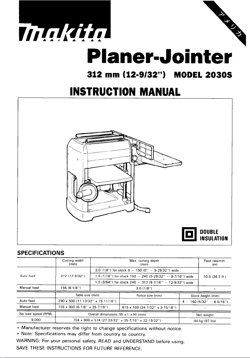
312
mm
(12-9/32")
MODEL
INSTRUCTION MANUAL
2030s
DOUBLE
INSULATION
SPEC
Auto
feed
Manual feed
Auto
feed
Manual feed
No load speed
9,000
I
FI
CAT1
(RPMI
0
N
S
Cutting width Max. cutting depth
Imml
312 (12-9/32"1
155 16-1/8"1
Table
290
x
500
I1
155
x
900 (6-118" x 35~7116") 615
704 x 900 x 574 (27~23132" x 35~7116" x 22~19132")
3.0 (118")
for stock
1
5
(1/16"1
for
1.0 13/64']
size
lmml
1-13/32" x 19-1 1/16")
Overall dimensions
for stock
stock
(W
0
-
150
240
x
100
x
L
x
HI
Imml
150
(0''
~
5-29132"1
wide
~~
240 15-29/32" ~ 9-7/16"]
~-
312 (9.7116" - 12-9/32"]
3
0
(118")
Fence size
(mml
~ 4
124~7132" x 3~15116")
lmml
Feed rateimin
lml
10.5 (34.5
wide
wide
Stock height
-
160 15/32" - 6-5/16")
44
~
Net weight
kg
197
-
lmml
lbsl
ft.1
Page 2

For
Your Own Safety Read Instruction
Manual Before Operating Planer-Jointer
GENERAL SAFETY PRECAUTIONS
(For
All
Tools)
1.
KNOW YOUR POWER TOOL. Read the owner’s manual carefully. Learn the
tools applications and limitations, as well as the specific potential hazards
peculiar to
2.
KEEP GUARDS IN PLACE and
3.
REMOVE ADJUSTING KEYS AND WRENCHES. Form habit of checking to
see that keys and adjusting wrenches are removed from tool before turning
it
on.
4.
KEEP WORK AREA CLEAN. Cluttered areas and benches invite accidents.
5.
DON‘T USE IN DANGEROUS ENVIRONMENT. Don’t use power tools
or wet locations, or expose them to rain. Keep work area well lighted.
6.
KEEP CHILDREN AWAY. All visitors should be kept safe distance from work
area.
7.
MAKE WORKSHOP KID PROOF with padlocks, master switches, or by
removing starter keys.
8.
DON’T FORCE TOOL.
it
was designed.
9.
USE RIGHT TOOL. Don’t force tool or attachment to do a job for which
was not designed.
IO.
WEAR PROPER APPAREL. Wear no loose clothing, gloves, neckties, rings,
bracelets, or other jewelry which may get caught
footwear is recommended. Wear protective hair covering to contain long hair.
11.
ALWAYS USE SAFETY GLASSES. Also use face or dust mask
operation is dusty. Everyday eyeglasses only have impact resistant lenses,
they are NOT safety glasses.
12.
SECURE WORK. Use clamps or a vise to hold work when practical. It‘s safer
than using your hand and
13. DON’T OVERREACH. Keep proper footing and balance at all times.
14.
MAINTAIN TOOLS WITH CARE. Keep tools sharp and clean for best and
safest performance. Follow instructions for lubricating and changing accessories.
15.
DISCONNECT TOOLS before servicing; when changing accessories such as
blades, bits, cutters, and the like.
it.
in
working order.
in
damp
It
will do the job better and safer at the rate for which
in
moving parts. Nonslip
if
cutting
it
frees both hands to operate tool.
it
2
Page 3
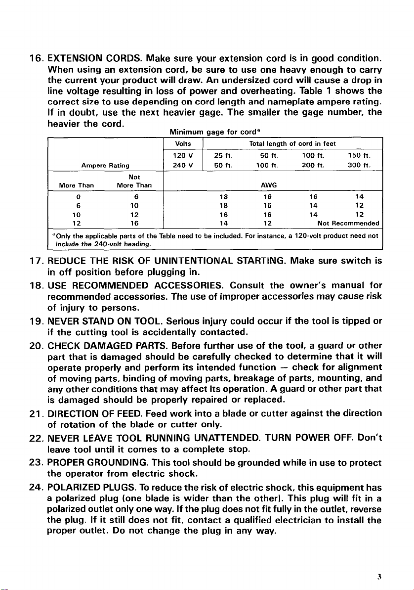
16.
EXTENSION CORDS. Make sure your extension cord is
in
good condition.
When using an extension cord, be sure to use one heavy enough to carry
the current your product will draw. An undersized cord will cause a drop
line voltage resulting
in
loss
of power and overheating. Table 1 shows the
in
correct size to use depending on cord length and nameplate ampere rating.
If in doubt, use the next heavier gage. The smaller the gage number, the
the
heavier
More Than More Than
aOnly the applicable parts of the Table need to be included. For instance, a 120-volt product need not
I
include the 240-volt heading.
cord.
Ampere Rating
0
6
Not
12
16
Minimum
Volts
120V 25ft. 50 ft.
240 V 50 ft.
6
aaae
for
18
18
16 16
14
cord"
Total length of cord in feet
100
ft.
AWG
16
16
12
100
200
16
14
14
ft. 150 ft.
ft.
Not
300
ft.
14
12
12
Recommended
17. REDUCE THE RISK OF UNINTENTIONAL STARTING. Make sure switch is
in off position before plugging in.
18.
USE RECOMMENDED ACCESSORIES. Consult the owner's manual for
recommended accessories. The use of improper accessories may cause risk
of injury to persons.
19.
NEVER STAND ON TOOL. Serious injury could occur if the tool is tipped or
if
the cutting tool is accidentally contacted.
20. CHECK DAMAGED PARTS. Before further use of the tool, a guard or other
it
part that is damaged should be carefully checked to determine that
-
operate properly and perform its intended function
check for alignment
will
of moving parts, binding of moving parts, breakage of parts, mounting, and
any other conditions that may affect its operation. A guard or other part that
is damaged should be properly repaired
or
replaced.
21. DIRECTION OF FEED. Feed work into a blade or cutter against the direction
of rotation of the blade or cutter only.
22.
NEVER LEAVE TOOL RUNNING UNATTENDED. TURN POWER
leave tool until
23.
PROPER GROUNDING. This tool should be grounded while
it
comes to a complete stop.
OFF.
in
use to protect
Don't
the operator from electric shock.
24. POLARIZED PLUGS. To reduce the risk of electric shock, this equipment has
a polarized plug (one blade is wider than the other). This plug will fit in a
If
polarized outlet only one way.
If
it
the plug.
still does not fit, contact a qualified electrician to install the
the plug does not fit fully in the outlet, reverse
proper outlet. Do not change the plug in any way.
3
Page 4

VOLTAGE WARNING: Before connecting the tool to a power source (receptacle,
outlet, etc.) be sure the voltage supplied is the same as that specified on the
nameplate of the tool. A power source with voltage greater than that specified
for the tool can result
If
in
the tool.
voltage less than the nameplate rating is harmful to the motor.
doubt, DO NOT
in
SERIOUS INJURY to the user - as well as damage to
PLUG
IN THE TOOL. Using a power source with
ADDITIONAL SAFETY RULES
&
FOR JOINTER
1.
Don't use the tool
2. Handle the blades very carefully.
3.
Check the blades carefully for cracks
cracked or damaged blades immediately.
4.
Be sure the planer blade installation bolts are securely tightened before
operating.
5.
Sharpen both blades evenly, or replace both blades
at the same time.
6.
Remove nails and clean the workpiece before cutting. Nail, sand or other
matter can cause blade damage.
7.
Make sure the blade is not contacting workpiece before the switch is turned
on.
8.
Wait until the blades attain full speed before cutting.
9.
Keep hands away from rotating parts.
IO.
Stop operation immediately
11.
Always switch off and wait for blades to come
adjusting any parts, cleaning out chips or approaching the blade.
12.
Never stick your finger into the chip chute. Chute may jam when cutting
damp wood. Turn off the planer-jointer and then clean out chips with a stick.
13.
Do not touch blades right after operation, they may be extremely hot and
could burn your skin.
14.
Don't abuse cord. Never yank cord to disconnect from receptacle. Keep cord
from heat, oil and sharp edges.
15.
Do not use auto-planer and jointer at the same time. Overloading of the motor
can occur.
in
presence of flammable liquids or gases.
if
AUTO-PLANER
or
damage before operation. Replace
or
both cutterhead covers
you notice anything abnormal.
to
a complete stop before
4
Page 5

FOR
1.
2. Do not perform jointing operations on material shorter than
3.
4.
5.
6.
JOINTER
Maintain the proper relationships of infeed and outfeed table surfaces and
cutterhead blade path.
140
mm (5-1/2
19
inches), narrower than
Do not perform planing operations on material shorter than 140 mm (5-1/2
inches), narrower than
or thinner than 12.7 mm (112 inch).
Support the workpiece adequately at all times during operation; maintain
control of the work at all times.
Do
not back the work toward the infeed table.
Do not attempt to perform an abnormal or little-used operation without study
and the use of adequate hold-down/push blocks, jigs, fixtures, stops and the
like.
mm (3/4 inch), or less than 12.7 mm (112 inch) thick.
19
mm (3/4 inch), wider than 155 mm
(6-1/8
inches)
FOR AUTO-PLANER
1.
Two or more pieces of narrow but similar thickness stock can be passed
through the auto-planer side by side.
However, allow some spacing between the stock to permit the feed rollers
to grip the thinnest piece.
Otherwise, a slightly thinner piece could be kicked back by the cutterhead.
2.
Determine the depth of cut according to the table shown on the front of the
tool. Do not attempt to cut more than the specified amount in one pass.
WARNING
For Your Own Safety, Read Instruction Manual Before Operating Jointer
1.
Wear eye protection.
2.
Never perform jointing or planing operation with cutter head or drive guard
removed.
3.
Never make jointing or planing cut deeper than 3 mm (118 inch).
4.
Always
mm
use hold-down/push blocks for jointing material narrower than 76.2
(3
inches), or planing material thinner than 76.2 mm
(3
inches).
SAVE THESE INSTRUCTIONS.
5
Page 6
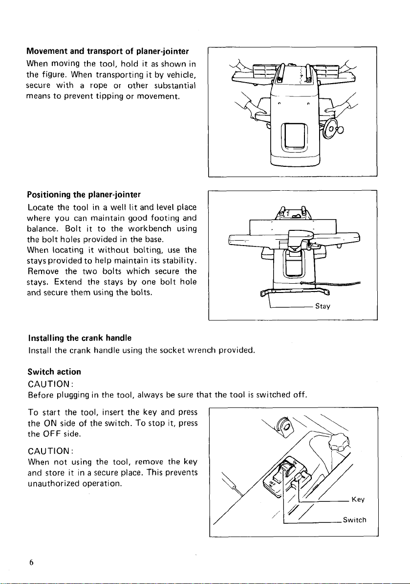
Movement and transport
When moving the tool, hold it
the figure. When transporting
a
secure with
rope or other substantial
of
planer-jointer
as
shown in
it
by vehicle,
means to prevent tipping or movement.
Positioning the planer-jointer
Locate the tool in a well
lit
and
level
place
where you can maintain good footing and
balance. Bolt it to the workbench using
the bolt holes provided in the base.
When locating
it
without bolting, use the
stays provided to help maintain its stability.
Remove the two bolts which secure the
stays. Extend the stays by one bolt hole
and secure them using the bolts.
Installing the crank handle
Install the crank handle using the socket wrench provided.
Switch action
CAUTION
:
Before plugging in the tool, always be sure that the tool is switched off.
start
To
the
the
CAUTION
the tool, insert the key and press
ON
side of the switch.
OFF
side.
:
To
stop it, press
When not using the tool, remove the key
a
and store it in
secure place. This prevents
unauthorized operation.
6
Page 7
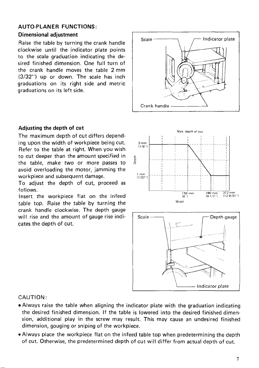
AUTO-PLANER FUNCTIONS:
Dimensional adjustment
Raise
the table by turning the crank handle
clockwise until the indicator plate points
to the scale graduation indicating the de-
sired finished dimension. One full turn of
2
the crank handle moves the table
(3/32")
graduations on
graduations on
Adjusting the depth
The maximum depth
up or down. The scale has inch
its
right side and metric
its
left side.
of
cut
of
cut differs depend-
mm
ing upon the width of workpiece being cut.
at
Refer to the table
right. When you wish
to cut deeper than the amount specified in
the table, make two or more passes to
avoid overloading the motor, jamming the
workpiece and subsequent damage.
To adjust the depth of cut, proceed
as
follows.
Insert the workpiece flat on the infeed
table top.
Raise
the table by turning the
crank handle clockwise. The depth gauge
will rise and the amount of gauge rise indicates the depth of cut.
I
Scale-\ Indicator plate
I
Crank handled
Max
demh
of
cut
3
mm
(1
18")
s
d
1
"
(1132"l
150"
16
I
Width
Scale
7
nm
132"l
&\'
Indicator plate
CAUTION
Always raise the table when aligning the indicator plate with the graduation indicating
the desired finished dimension.
sion, additional play in the screw may result. This may cause an undesired finished
dimension, gouging
*Always place the workpiece flat on the infeed table top when predetermining the depth
of cut. Otherwise, the predetermined depth of cut will differ from actual depth of cut.
:
If the table
or
sniping of the workpiece.
is
lowered into the desired finished dimen-
7
Page 8
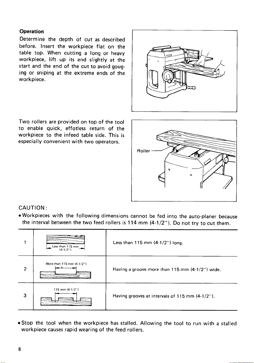
Operation
Determine the depth of cut
before. Insert the workpiece flat on the
table top. When cutting
workpiece, lift up
start and the end of the cut to avoid goug-
ing or sniping
i
ece.
work p
Two rollers are provided on top of the tool
to enable quick, effotless return
workpiece to the infeed table side. This
especially convenient with two operators.
its
at
the extreme ends of the
as
described
a
long or heavy
end slightly
at
of
the
the
is
Roller
CAUTION
e
Workpieces with the following dimensions cannot be fed into the auto-planer because
the interval between the two feed rollers
1
7-
3
estop the tool when the workpiece has stalled. Allowing the tool to run with a stalled
workpiece causes rapid wearing
8
:
I
1
I
Less
Fq
More than
than
11 5 mm
11
5
mm
(4-1i2")
115mm(4112
is
114
mm
I
1
Less than
I1
5
mm
(4-1/2").
(4-1
/2")
Do
not try to cut them.
long.
I
Having a groove
more
than
115
mm
(4-1/2")
wide.
I
I
Having grooves at intervals
of
the feed rollers.
of
11
5
mm
(4-1
/2").
Page 9
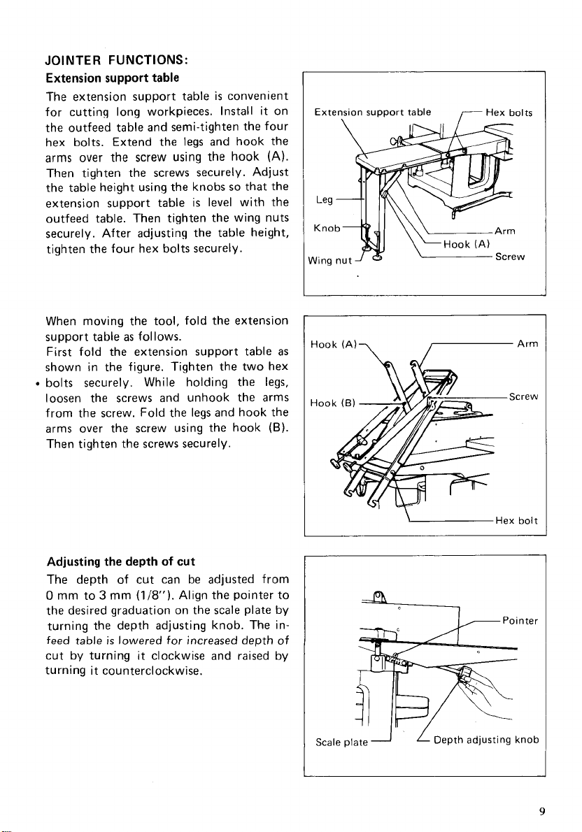
JOINTER FUNCTIONS:
Extension support table
The extension support table
for cutting long workpieces. Install
is
convenient
it
on
the outfeed table and semi-tighten the four
hex bolts. Extend the
arms over the screw using the hook
legs
and hook the
(A).
Then tighten the screws securely. Adjust
the table height using the knobs
extension support table
so
that the
is
level with the
outfeed table. Then tighten the wing nuts
securely. After adjusting the table height,
tighten the four hex bolts securely.
When moving the tool, fold the extension
as
support table
First fold the extension support table
follows.
as
shown in the figure. Tighten the two hex
bolts securely. While holding the
legs,
loosen the screws and unhook the arms
from the screw. Fold the legs and hook the
arms over the screw using the hook
(6).
Then tighten the screws securely.
I
Extension support table
Hook
(A)-,
7
Hex bolts
1-
Arm
Screw
Adjusting the depth
of
cut
The depth of cut can be adjusted from
0
mm to 3 mm
the desired graduation on the
(1/8").
Align the pointer to
scale
plate by
turning the depth adjusting knob. The in-
feed
table
is
lowered for increased depth of
cut by turning it clockwise and raised by
turning it counterclockwise.
I
Scale plate
VI
1
;Hex
L
Depth adjusting knob
bolt
9
Page 10

Adjusting the fence angle
The fence angle can be adjusted
angle from
screws
slightly. Then tighten the clamp screws (A)
and
(B).
and
tilt
Then tighten the hex bolts
securely.
Operation
Placement of hands during feeding
At the start
and firmly against the fence. The right hand pushes the workpiece toward the blades.
After the cut has started, the new surface rests firmly on the outfeed table. The left hand
should press down on this part well away from directly over the cutterhead,
time maintaining flush contact with the fence. The right hand presses the workpiece
forward and before the right hand passes over the cutterhead
moved to the workpiece on the outfeed table.
0’
to 45’. Loosen the clamp
(A)
and
(B)
and pull the fence out
Loosen the hex bolts
the fence according to your work.
of
the cut, the left hand holds the workpiece firmly down on the infeed table
(A)
(A)
at
and
and
any
(B)
(B)
I
ClamD
screw
(A)
7
it
should be cautiously
Hex bolts
-Fence
bolts
at
the same
(A)
(6)
Jointing an edge
Set the fence square with the table. Hold
the best fece of the workpiece firmly
against the fence throughout the feed. Side
is
pressure
in flush contact with the fence. This
important when jointing wide workpiece.
Surfacing
For surfacing, press the workpiece down
against the outfeed table. Surfacing or
planing
twisted board
plish. Hold-down/push blocks be useful in
all
cases.
surfacing workpieces thinner than
(3”).
the dished (hollow, concave) surface first,
whenever possible. Small depths of cut
only should be taken whenever surfacing
warped workpieces.
10
required to keep the workpiece
a
wide work surface on a warped or
is
very difficult to accom-
They should always be used when
If the workpiece
is
warped
m
is
76.2
,
very
mm
joint
Fence
I
L-1
Joint
Joint edge of workpiece on
dished side whenever possible
Page 11

Beveling
To cut a bevel,
while keeping
set
the fence
it
firmly against the fence and tables. Carefully maintain flush, steady con-
at
the required angle and run the workpiece across the blades
tact with the fence while making the cut.
REPLACING THE PLANER BLADES
Dull blades can cause a rough finish, an overload of the motor and dangerous kickback of
is
the workpiece. Sharpen or replace dull blades immediately. This tool
equipped with
either throw-away blades or standard blades. The method of replacing the blades differs
depending upon the type of the blade. Follow the correct method for your tool.
CAUTION
*Always be sure that the tool
:
is
switched off and unplugged before removing or installing
the blades.
0
Handle the blades very carefully when removing or installing the blades to prevent cuts
or injury from the blades and to prevent damage to the blades. They are razor-sharp.
0
Clean out all chips, dust, pitch or foreign matter adhering to the drum or blades before
installing the blades.
0
Use blades of the same dimensions and weight, or drum oscillation/vibration will result,
causing poor cutting action and, eventually, tool breakdown.
Replace both blades
.The throw-away blade has
at
the same time.
a
cutting edge on both sides. When one cutting edge becomes
dull, you can use the other cutting edge. Always remove resin and dirt sticking to the
reverse
side
of
the blade before using
the
other cutting edge. This blade must not
be
sharpened. When both cutting edges become dull, the blade should be carefully thrown
away.
re-
11
Page 12

AUTO-PLANE
1.
Removing
Loosen the hex bolt which secures the
chip cover and open the chip cover.
Open the safety cover over the jointer
and rotate the drum by turning the
knob until the drum can be locked in
the position whereby the blade installation bolts face upward.
The magnetic holder has
shaped claw on each side. Use the correct claw for auto-planer.
R
the
blades
a
different
Knob
1
Hex bolt
For jointer
Blad; installation bolt
Claw
M
I
Place the two magnetic holders on the
arrow until the claw contacts the blade. Remove the eight blade installation bolts using
the socket wrench. Grip the magnetic holders and raise them straight up to remove the
set
plate and blade from the drum. Press the lock plate and rotate the drum by turning
180"
the knob
to lock the drum. Remove the other blade
I
Blade installation bolt
set
plate and push them in the direction of the
as
described above.
-
Magnetic holder
Socket wrench
L
Magnetic holders
12
Page 13

2.
Installing the blades
Provide a flat wood block approx.
100
300 mm (1 1-13/16") long and
(3-15/16") wide. Place the blade and
plate on the wood block
blade locating lug of the
so
set
mm
set
that the
plate rests
in the groove of the blade. Adjust the
set
plate
so
that both ends of the blade
protrude approx. 1 mm (3/64") beyond
the end of the
magnetic holders on the
set
plate. Place the two
set
plate and
push them until the claw contacts the
blade (Note: Use the correct claw for
auto-planer.
Grip the magnetic holders and slip the
heel of the
set
plate into the groove in
the drum. Install the blade installation
bolts.
Magnetic holder
Set
plate
(3/64")
I
~
Blade installation bolt
Magnetic holder
Blade
After tightening all the blade installation bolts lightly and evenly from the
center to the outside, tighten them completely following the same sequence.
Remove the magnetic holders from the
set
plate.
-Socket wrench
Magnetic holders
13
Page 14

Install the other blade
as
plate to make sure there
the hex bolt.
described above. Rotate the drum slowly while pressing the lock
is
nothing abnormal. Then close the chip cover and secure using
CAUTION
0
Do
correctly resting in the groove
:
not tighten the blade installation bolts without
of
the blade. This may cause damage to the blade and
the
blade locating lug
potential injury to the operator.
0
Tighten the blade installation bolts securely when installing the blades.
Do
not turn the tool on with the chip cover open.
of
the
set
plate
14
Page 15

JOINTER
1.
Removing the
CAUTION
Always close the chip cover over the auto-planer before removing the blade.
Lower the infeed table fully by turning
the depth adjusting knob clockwise.
Loosen the hex bolt which secures the
safety cover rod and lift off the safety
cover. Set the fence angle
push the fence fully toward the autoplaner. Pull the lock pin and rotate the
drum by turning the knob to lock the
drum in the position whereby the blade
installation bolts face upward.
(NOTE)
The drum can be locked in two different positions. One position
edge faces upward and the other
Remove the four blade installation bolts
and the drum plate. Place the two magnetic holders on the
The magnetic holder has
shaped claw on each side. Use the correct claw for jointer.) Push them in the
direction of the arrow until the claw
contact the blade.
:
blades
at
set
plate. (Note:
a
0'
and
Lock
pin
-
is
where the blade installation bolts face upward.
different
is
where the blade
Grip the magnetic holders and raise
them to remove the
from the drum. Pull the lock pin and
rotate
the drum by turning the knob
180'
to lock the drum. Remove the
other blade
as
set
plate and blade
described above.
15
Page 16

2.
Installing the blades
Provide a flat wood block approx.
150
mm
(5-29/32")
(3-1
5/16")
wide.
plate on the wood block
blade locating lug of the
long and
Place
the blade and
so
set
plate rests
100
that the
in the groove of the blade. Adjust the
set
plate
so
that both ends of the blade
do not protrude from the ends of the
set
plate. Place the two magnetic holders
set
on the
plate and push them until the
claw contacts the blade. (Note: Use the
correct claw for jointer.)
Lock the drum in the position whereby
the blade installation bolts face upward.
Place the
drum
set
plate and blade on the
so
that the heads of the depth
adjusting screws in the drum fit into the
set
square holes in the
plate. Remove
the magnetic holders while holding the
set
plate with your hand.
mm
set
Place the drum plate on the
set
Install the blade installation bolts and
semi-tighen them.
16
plate.
Page 17

Lock the drum in the position whereby
the
blade edge faces upward. Place the
triangular rule flat on the outfeed table.
Turn the adjusting screws until the
blade edge just contacts the triangular
rule. After adjusting both adjusting
screws, pull the lock pin to unlock the
drum. Rotate the drum by turning the
knob clockwise to make sure the blade
is
at
protrusion
all
the way across.
exactly the same height
If
not, adjust the
adjusting screws again.
After carefully adjusting the blade protrusion, lock the drum in the position
whereby the blade installation bolts
face upward. Securely tighten the blade
installation bolts evenly from the center
of the outside.
Outfeed
table
Then slightly retighten the adjusting
screws by turning clockwise.
I
17
Page 18

Install the other blade
as
described above.
Re-install the safety cover in
position and be sure that the safety cover works properly and briskly.
its
original
CAUTION
Do
plate correctly resting in the groove
:
not tighten the blade installation bolts without the blade locating lug of the
of
the blade. This may cause damage to the blade
and potential injury to the operator.
Tighten the blade installation bolts securely when installing the blades.
Always be sure that the drum
is
unlocked after installing the blades.
set
18
Page 19

REMOVING
CAUTION
Always be sure that the tool
the jointer.
The jointer can be easily removed from the auto-planer.
1.
Removing the jointer
Loosen the right and left knobs. Pull the
jointer toward
figure. The jointer can be removed.
OR
INSTALLING THE JOINTER
:
is
switched off and unplugged before removing or installing
you
as
shown in the
You
can carry
it
by yourself.
is
When the jointer
cover will close automatically. If
lock the pulley cover in the open position for some reason, be sure to close
by pushing the release button before
operating the auto-planer. Never operate
the auto-planer with the pulley cover
locked in the open position.
2.
Installing the jointer
Open the pulley cover until
locked. Align the line on the pulley with
the pointer on the side cover (L).
removed, the pulley
it
you
will be
-
I
it
/--
,-Pointer
/=I
\\\
\L'
-
Side
Pulley cover
..
.
Knob
cover
'
(L)
Line
Pulley
19
Page 20

Loosen the clamp screws which secure
the fence. Remove the fence. Align the
line on the coupling with the pointer on
the frame of the jointer.
I
Coup1 ing
s
eoin
Align the two shafts of the jointer with the mating holes in the auto-planer. Push the
jointer toward the auto-planer until the frame of the jointer contacts that of the autoplaner. Make sure the jointer
contact portion through the notch. Tighten the knobs to secure the jointer. Re-install
the fence and tighten the clamp screws to secure the fence.
Mating
is
correctly installed on the auto-planer
r
‘lamp
Screw
by
viewing the
Knob
Line
t
e
r
20
Knob
See this contact portion
-/
-Shaft
of
jointer
through notch.
2
Page 21

MAINTENANCE
CAUTION
Always be sure that the tool
inspection or maintenance.
:
is
switched off and unplugged before attempting to perform
Replacing carbon brushes
Remove and check the carbon brushes re-
gularly. Replace when they wear down to
the limit mark. Keep the carbon brushes
clean and free to slip in the holders. Both
at
carbon brushes should be replaced
same time. Use only indentical carbon
brushes.
Open the chip cover and remove the brush
holder caps using
the worn carbon brushes, insert the new
ones and secure the brush holder caps.
Lubrication
Oil the chain (after removing the side cover
R),
the column moving parts (contact areas)
and the crank handle. This periodic lubrication should be performed with machine oil.
a
screwdriver. Take out
the
c
1
L
Brush holder cap
I
\
Limit
mark
Screwdriver
CAUTION
Oiling and
with
To maintain product SAFETY and RELIABILITY, repairs, any other maintenance and
adjustment should be performed by Makita Authorized or Factory Service Centers,
always using Makita replacement parts only.
:
all
maintenance should be done
the tool turned
off
and unplugged.
21
Page 22

ACCESSOR I ES
ATTENTION
These accessories or attachments are recommended for use with your Makita tool specified in this
manual. The
accessories or attachments should be used only in the proper and intended manner.
0
Planer blade
Socket wrench
Part No. 782203-5
IO'
(For auto-planer)
Part No. 192382-5
set
:
use
of
any other accessories or attachments might present a risk
0
Magnetic holder
Part No. 76201 7-8 Part No.
0
9
Screwdriver
Part No. 783002-8
c
0
Hood set
(For jointer)
Part No. 192383-3
of
injury to persons. The
0
Key
0
Triangular rule
Part No. 762001-3
0
Y
joint assembly
Part No. 122342-3
0
Extension support table
Part No. 192381-7
22
0
Push
Part
block
No. 155508-0
Page 23

312
mm
(12-9/32”)
PLANER-JOINTER
Model
2030s
Mar-22-’94
US
23
Page 24

24
Page 25

Note: The switch and other part configurations
may differ from country to country.
25
Page 26

MODEL 2030s
'v0M
$&
INE
MA(
~
2
1
2
2
2
3
4
2
2
5
2
6
1
2
8
1
9
2
10
11
12
13
14
16
17
18
19
20
21
1
22
1
23
24
1
25
1
26
1
27
1
28
1
1
29
1
30
1
31
1
32
1
33
4
34
1
35
1
36
1
37
38
39
40
41
42
2
43
44
45
46
41
48
49
50
51
52
53
54
55
56
51
58
59
60
61
62
63
64
65
66
67
68
69
70
71
72
13
DESCRIPTION
Compression
Roller
Shaft
Roller
29-300
Compression Spring 14
Stop
Ring
Pan
Head
Stop
Ring
Pan
Head Screw
Chip Cover
Countersunk
Tube 10-108-15
Strain
Relief
lapping
Box
Switch
Switch
Tapping
Tapping Screw
Swttch Supporter
Strain
Relief
Tapping
Tapping
Strain
Relief
Switch
Box
Name Plate
G~W
nouslng
Makita
Label
Flat Washer 12
Helical
Gear
Woodruff
Drive Shaft
Flat Washer 14
ear
tiouslng
Pan Head
Torsion
Te"SlOn.3,
Sprocket 12
1
Retaining
1
Pan
Head
Tension
1
Plane
8earl"g
1
Ring
6
Pan
Head Screw
1
Flat Washer
1
Gear
Complete 8-44
1
Gear
Complete 8-47
1
Flat Washer
1
Flat Washer
flat
Washer
1
1
field
Poly
V
Belt
Carbon
2
Brush
2
2
1
1
1
1
1
1
1
Holder
Pan
Head
Motor
Housing
Pan
Head
Pan
Head
Baffle
Plate
V
Pulley 9-25L
Ball
Bearing
lnwlation Washer
Armature
Ball
Bearing 6200DDW
Main
Drum
Ball
Bearing
Ball
Bearing
Hex
Flange
Knob 40
Bearing
Countersunk
Lock Plate
Torsion Spring 12
Pan
Head
Soring
E
-
6
Screw
M5x16 (With Washer!
E-6
M5x60 (With Wanherl
Head
Screw
4x18
Screw
Bind
Flange PT4xl2
Screw
Flange PT4x12
Screw
Flange PT4x12
Cover
45
Key 4
COW
Screw
M5x85 IWifh Washer)
Spring 23
Ring
S-
Screw
M5x20 (With Washer)
Roller
5
M5x25 [With Washer!
8
8
6
6
9
314
Brush
Cap
Screw
M5x25 [With Washer)
Screw
M5x8O IWith Washer!
Screw
M5x80 [With Washer!
6200DDW
6202LLB
6202LLB
Head Bolt
Box
Head Screw
Screw
M5x25 (With Washer!
14
Screw
PT3x8
12
M4x30
M5x10
M5x16
MACHlNE
74 1
75 1
76 1
11
78 1
79 1
80 1
81 16
82 2
84 1
85
86
87
88
89
90
91 2
92 1
93 1
94 1
95
96
97 1
98 1
99
100 1
101
102 1
103 2
104 1
105 2
106 1
107 1
108 1
109 1
1
110 8
111 1
112
113
114
115
116
111
118
119
120
121
122
123
124
125
126
127
128
129
130
131
132
133
134
135
136
131
138
139
140
141
142
143
144
145
146
$&
DESCRIPTION
v
Hex
Key
Flat
1
Sleeve
Gauge
Main Frame
Hex
Set
Chain 35-50
1
Retaining
Sprocket 12
1
Metal Cover
1
Plane
1
1
Compression Spring 7
1
CDmPleSSlOn spmg 13
Hex
Retaining
Sprocket 12
Metal
Hex
2
Plane
1
Compression Spring 13
Roller
Knob 40
1
Compression Spring 13
Plane
1
Metal
Hex
Metal
Hex
Compression Spring 13
Plane
Roller
Table
Countersunk
1
Hex
1
Flat Washer 8
Table
1
1
Pan
Indicator
1
1
set Plate
Pan
1
Woodruff
1
1
Screw
1
Thrust
1
Straight
Flat Washer 10
1
1
Compression Spring 15
Stop
1
1
Handle
Retaining
1
Straight
Spmg
1
Pan
2
Stop
1
Flat Washer
1
Knob 45
1
P,"
1
1
Handle
Handle
1
Hex
1
Pan
2
Side
1
Pan
2
Side
1
Foot
1
1
Leg
Cord
1
Strain
Pan
1
Hex
Pulley
9-58
Socket
Head
4
Washer
6
5
Flange
Head
Plate
310
Ring
18)
Bearing 17
Socket
Head
Ring
Cover
IB!
Socket
Head
Bearing
34-295
Bearing
Cover
IAI
Socket
Cover IAl
Socket
Bearing
34-295
Plate
Lock
Nut ME-13
Head
Screw
Head
Screw
Key 3
M16
Needle
Bevel
Ring
E
-
Shaft
Ring
Bevel
P,"
4-
Head
Screw
Ring
E
-
8
8
Supporter
125
Flange
Head
Head Screw
Cover L
Head Screw
Cover R Complete
Relief
Head
Screw
Flange
Bolt
M6x12
Bolt M6x17
5-
12
Bolt
M5x16 [With Washer!
S-
12
Bolt
M5x16 IWJth Washer!
17
17
Head
Bolt
M5x16 IWith Washerl
Head Bolt
M5x16 lWith Washer!
11
Head Screw
M4x12
M5x8 IWith Washer!
M5x8 [With Washer]
Bearing 1023
Gear
16
12
S-
10
Gear
16
18
M5x16 IWith Washerl
6
Bolt M5x10
M5x30 IWtth Washer!
M5x30 IWith Washer!
M4x12 IWith Washer!
Head
Bolt M6x17
Mar.-22-'94
US
26
Page 27

MODEL
20305
'y0M
sD
DESCRIPTION
MACHINE
__
147 1
148 1
149 1
150 1
151 1
152 4 Spring Pin 6 36
153 1
154 4 Cap 20
155
158 1
157 1 SpringPin4-16
158
159 1
160 1
161 2
162 1
163 1
164 20
165 1
166 1 Spring Pin 4- 18
167 1 SpringPin4-18
168 1
169 2
170
171
172
173
174 2 Pan
175
176 1
177 1
178 2 Pan
179 1
180 1
181 2 Pan
182 1
183 1
Hex Flange Head Bolt
Leg
Foot
Base
Pan
Head Screw
Base
1
Drum
Retaining
1 Spring
Rod
12-95
Torsion
Bedplate
Adlust
Indication
Countersunk Head
Knob
Flat Washer
Pan Head
1
Screw
1
Flat Washer
1
Hex Flange Head Bolt
1
Hex Flange Head Bolt
Head Screw
1
Rule
Holder
Ruler
Safety
Head
Ruler
Rule Holder
Head
Hex
Hex Flange Head
Cover
cover
Pin
Spring 14
Bed
40
Holder
Bar
Cover
Bar
Flange Head Bolt
M5x16
Ring S 12
4-32
Label
10
Screw
M5x16
10
M5x16
L
Screw
M5x16
R
Screw
M5x16
Screw
8011
M6x17
IWith Washer)
M4xl2
IWith Washerl
M6x17
M6x17
(With Washerl
(With Washerl
IWith Washerl
M6x17
M6x17
ITEM
NO
NO. USED
MACHINE
__
184 1
185 1
186 1
187 4
188 1
189 1
190 1
191 1
192 1
193 1
194 2
195 1
196 2
197 1
198 1
199 1
200
201 1
202 1
203
204 2
205
206 2
207 1
208
209 2
210 2
211 1
212 1
213 1
214 4
215 1
217 2
218 2
219 8
220 1
DESCRIPTION
Ruler
Set
Screw
Lock
Sleeve
Pan
Head Screw
Bearing
Nut
M4 12
stopper
Pln 2
compression
Hex
Flange Head Bolt
Pan
Head
Scale Plate
Screw
Fix Bed
Rod
17 63
Coupling
Hex Socket Head Bolt
1
Coupling
Set
Screw
Key
4
I
Cup Washer 8
Rod
17-90
1
Flat Washer
Set
Screw
Compression Spring
2
Hex Socket Head
Pan
Head
Chip Guide
Pan
Head
Sub
Drum
Flat
Head Screw
Ball
Bearing
set Plate
Drum
Hex Flange Head
Ball
Bearing
Cover
Pln
M6x19
Cushion
Plate
M5x8
sprmg
Screw
M5x12
8
M5x12
Screw
Screw
6200DDW
155
6201DDW
M5x16
(With
5
M5x10
M5x8
(With Washerl
M6x12
9
Bolt
Max50
M5x16 (With
M5x16
lWith Washer]
M5x13
Bolt
M6x17
Mar-22-'94
Washerl
Washer)
US
21
Page 28

MAKITA
LIMITED
ONE
YEAR
WARRANTY
Warranty Poiicy
Every Makita
be free of defects from workmanship and materials for the period of ONE YEAR from the date of
original purchase. Should any trouble develop during this one-year period, return the COMPLETE
tool,
the trouble is caused by defective workmanship or material, Makita will repair (or at our option,
replace) without charge.
This Warranty does not apply where:
repairs have been made or attempted by others:
repairs are required because of normal wear and tear:
The tool has been abused, misused or improperly maintained;
alterations have been made
IN NO EVENT SHALL MAKITA BE LIABLE FOR ANY INDIRECT, INCIDENTAL OR CONSEQUENTIAL DAMAGES FROM THE SALE OR USE OF THE PRODUCT. THlS DlSCLAIMER
APPLIES BOTH DURING AND AFTER THE TERM
MAKITA DISCLAIMS LIABILITY FOR ANY IMPLIED WARRANTIES, INCLUDING IMPLIED
WARRANTIES OF “MERCHANTABILITY” AND “FITNESS FOR A SPECIFIC PURPOSE,”
AFTER THE ONE-YEAR TERM OF THIS WARRANTY.
This Warranty gives you specific legal rights, and you may also have other rights which vary from
state
damages,
limitation on how long an implied warranty lasts,
tool
is thoroughly inspected and tested before leaving the factory. It is warranted
freight prepaid,
to
state. Some states do not allow the exclusion
so the above limitation or exclusion may not apply
to
one of Makita’s Factory or Authorized Service Centers.
to
the tool.
so the above limitation may not apply
OF
THIS WARRANTY.
or
limitation
to
you. Some states do not allow
If
inspection shows
of
incidental or consequential
to
you.
to
Makita
3-11
-8,
Sumiyoshi-cho,
Anjo, Aichi
883863-069
Corporation
446
Japan
PRINTED
1996
IN
-
JAPAN
9
-
N
 Loading...