


---------------------------------------------------------------------------------------
Installation & Operating Manual
---------------------------------------------------------------------------------------
Packaged Make-Up Air
Heat Models EM-MC*, EM-MD*, EM-ME*, EM-MF*, EM-MG*
Included With This Product
Permanent washable air filter
Powered inlet damper
(2) temperature sensors
(1) current transformer (CT doughnut)
Chain kit for ceiling installations
Other Requirements
Low voltage (Class II type) wiring when using supply CT doughnut to control Make-Up Air unit
High voltage wiring
Fresh air intake wall or roof vent
Inlet/outlet ductwork
Application
This product aids in preventing building depressurization where there is single or multi-source exhaust
points, coupled with a tight building envelope such as:
Single, large exhaust source
- Kitchen range hood
Single or multi-speed exhaust blower interface
Multiple exhaust sources
- Bathroom fan, fireplace, dryer, gas furnace, dryer, etc.
Note
In applications where the exhaust fan utilizes a multi-speed blower, this product has the ability to
sense each fan speed by monitoring the amperage of the exhaust fan motor. After completing the
mechanical portion of the installation, see Multi-Speed Setup for further details explaining how
to utilize this unique feature. Configuring the Make-Up Air unit to vary its speed to closely match
the blower speed of the external exhaust source blower motor allows for balanced system
operation.
Conforms to: UL STD.UL1995
Certified to: CSA STD.C22.2#236
DO NOT DESTROY THIS MANUAL. PLEASE READ CAREFULLY AND KEEP IN A SAFE
PLACE FOR FUTURE REFERENCE BY A SERVICE TECHNICIAN.
08/14/2020 EI914

Table of Contents
Page
Product Description 1
Handling & Storage 1
Placement & Mechanical Information 1
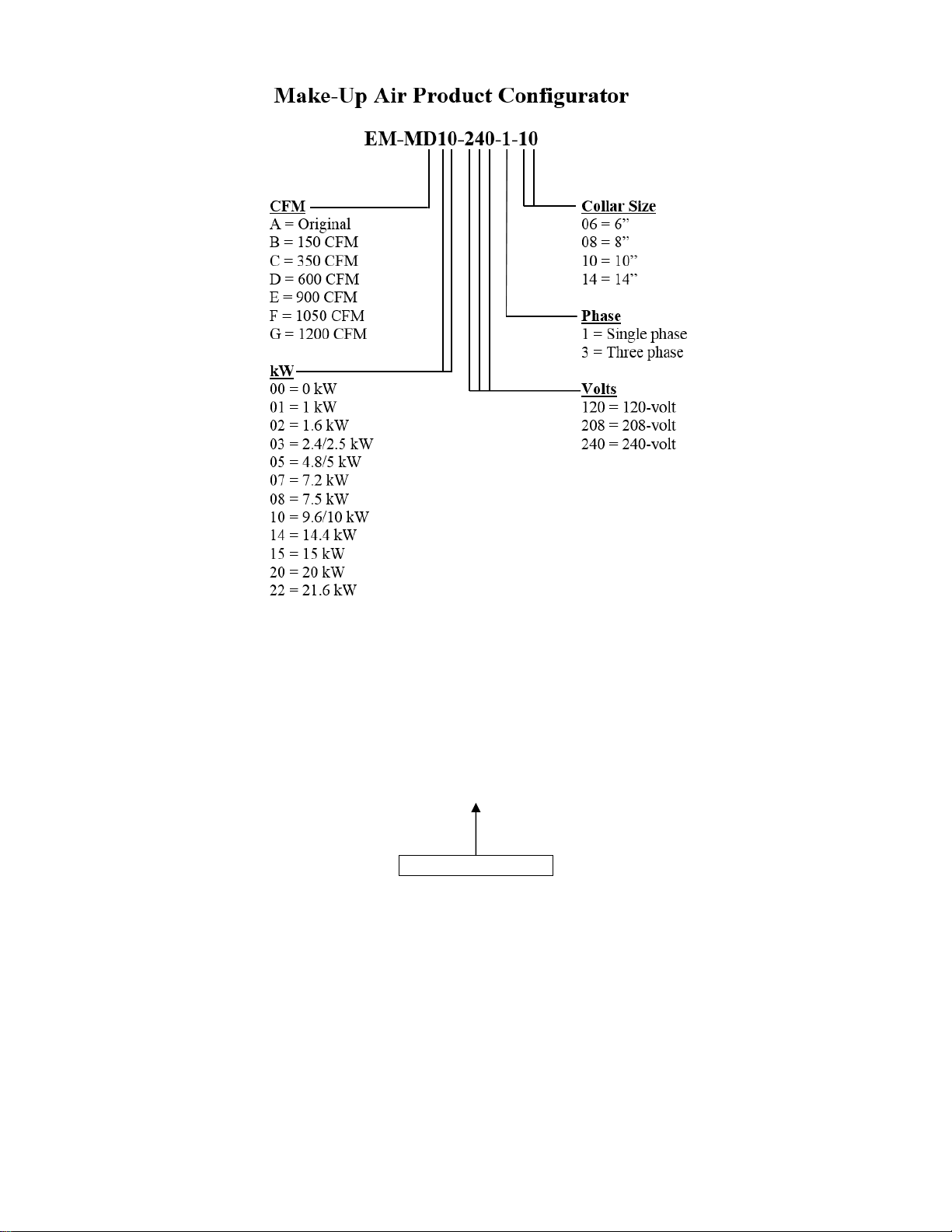
Product Configurator (EC904) 2
System Status 2
Specification Tables 3
Dimensional Drawings 4
Safety Consideration 5
Installation Requirements 5
Installation Overview 6
Mechanical Installation 7
Electrical Installation 10
Control Wiring 11
High Voltage Wiring 14
Basic Setup & Configuration 15
Software Configuration 17
Understanding the Product Display 18
Normal Operation Screens 19
Multi-Speed Setup 20
Operational Indicators 22
Start Up Inspection & Observations 23
Advanced Installation & Special Equipment Concerns 24
Troubleshooting 26
Routine Maintenance 28
LCD Display 29
Drawings UAW860
UAW861
UAW862
UAW866
UAW867
UAW868
UAW869
UAW870
UAW872
XX017
08/14/2020 EI914

Product Description
This is a self-contained package with a permanent (washable) air filter, electric heating elements,
modulating element temperature control, powered damper and blower. This product has been designed
specifically for outside air inlet.
All models include WarmFlo electronic outlet temperature sensor and associated control circuitry to
modulate the electric elements for a fixed outlet temperature. This means the electric element is only used
to “make-up” or heat the outside fresh air to the preset temperature point. There is no overheating or
inefficient use of the electric element.
Heating is locked out when entering air temperature is greater than 55°F (12.7°C).
All models (except EM-MB) include a multi-speed blower function; see Basic Setup & Configuration
for further detail.
Diagrams used throughout the installation manual represent general installation requirements. Due to
various model sizes available, actual unit mechanical and wiring requirements will vary dependent upon
specific model.
Handling & Storage
Receiving
It is the receiver’s (person and/or company signing off on the receiving Bill of Lading) responsibility to
inspect for shipping damage. All shipping claims must be made by the receiver.
Storage
Packed or unpacked, the Make-Up Air unit shall not be exposed to rain, snow, or other adverse
environment. This product is designed for in-building storage and installation only.
As much as possible this product must be protected throughout the construction phase to avoid
accumulation of dust and moisture on the components and control box. The installing contractor is
responsible for maintaining the cleanliness and quality of this unit until installation is complete and
approved by the user/end customer.
Placement & Mechanical Information
This product is designed for zero clearance, but use the following mounting and spacing criteria:
1. Unit can be installed vertically or horizontally. When vertical, inlet must face down.
2. When using CT doughnut, use Class II low voltage wiring methods to connect CT to Make-Up
Air unit.
3. Make mounting provisions for a 1” air space at the top.
4. The sides, any location, can be in direct contact with wood framing materials.
5. No materials shall be in contact with the cabinet housing which has a flame point less than wood,
300°F (150°C).
6. Product shall be installed in a conditioned space only.
7. Heating is locked out when entering air temperature is > 55°F (12.8°C).
08/14/2020 1 EI914
System Status
STATUS LED
Status LED (front yellow LED) – is software driven LED which alerts the user that a message is
available in the message center.
Status LED OFF = No message is available
Status LED Blinking = Message is available
o To access available messages, the user must press and hold the “SELECT”
Possible messages:
Faulty sensor (IN and/or OUT)
Manual hi-limit
Automatic hi-limit
Software hi-limit
See Troubleshooting section for more information on viewing available messages.
button for 3 seconds.
08/14/2020 2 EI914
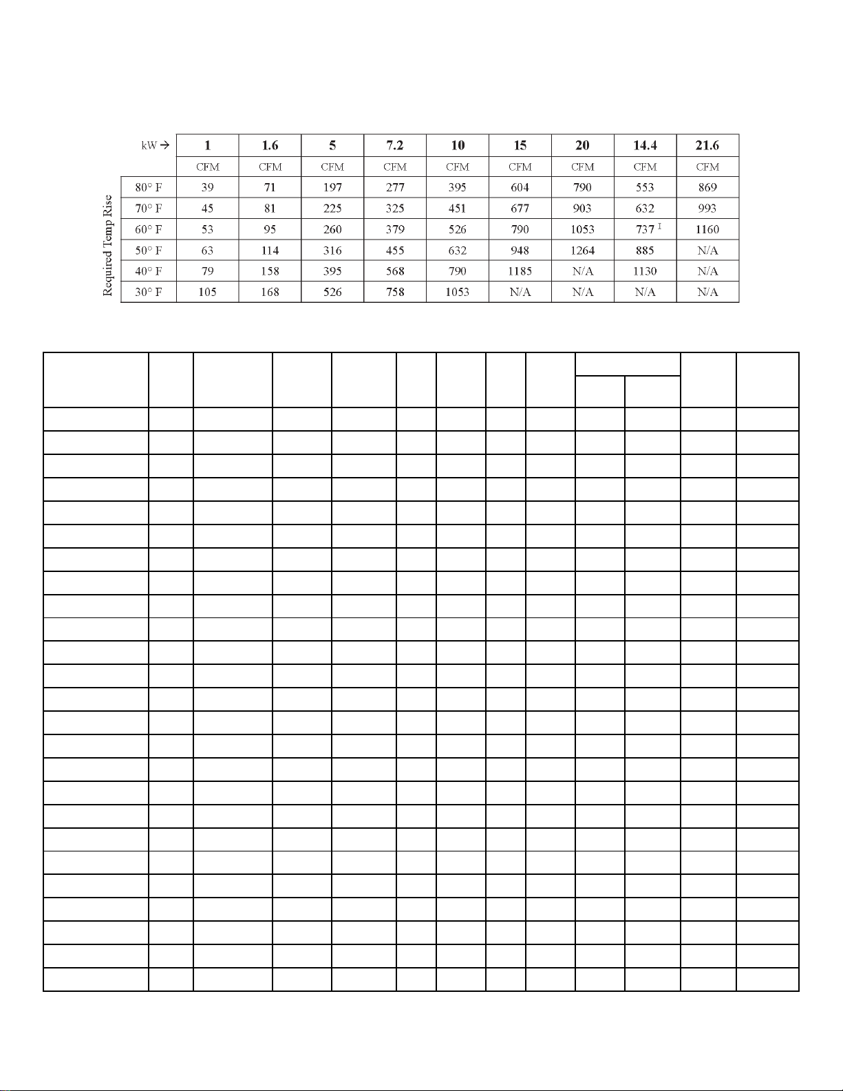
Specification Tables
Temperature Rise & CFM Chart
Specifications
Model
EM-MC05-240-1-08 5/3.8 17060/12795 20.8/18.0 N/A 0.4 1/10 1 240/208 350 .50 30 8”
EM-MC05-208-3-08 4.8 16378 13.3 N/A 0.4 1/10 3 208 350 .50 20 8”
EM-MD10-240-1-10 10/7.5 34121/25591 41.7/36.1 N/A 0.8 1/5 1 240/208 600 .50 60 10”
EM-MD05-240-1-10 5/3.8 17060/12795 20.8/18.0 N/A 0.8 1/5 1 240/208 600 .50 30 10”
EM-MD10-208-3-10 9.6 32756 26.6 N/A 0.8 1/5 3 208 600 .50 35 10”
EM-MD05-208-3-10 4.8 16378 13.3 N/A 0.8 1/5 3 208 600 .50 20 10”
EM-ME15-240-1-14 15/11.3 51182/38386 62.5/54.1 60A + 30A 1.5 1/4 1 240/208 900 .50 90 14”
EM-ME10-240-1-14 10/7.5 34121/25591 41.7/36.1 N/A 1.5 1/4 1 240/208 900 .50 60 14”
EM-ME05-240-1-14 5/3.8 17060/12795 20.8/18.0 N/A 1.5 1/4 1 240/208 900 .50 30 14”
EM-ME14-208-3-14 14.4 49134 40.0 50A 1.5 1/4 3 208 900 .50 50 14”
EM-ME10-208-3-14 9.6 32756 26.6 N/A 1.5 1/4 3 208 900 .50 35 14”
EM-ME05-208-3-14 4.8 16378 13.3 N/A 1.5 1/4 3 208 900 .50 20 14”
EM-MF15-240-1-14 15/11.3 51182/38386 62.5/54.1 60A + 30A 1.5 1/4 1 240/208 1050 .50 90 14”
EM-MF10-240-1-14 10/7.5 34121/25591 41.7/36.1 N/A 1.5 1/4 1 240/208 1050 .50 60 14”
EM-MF05-240-1-14 5/3.8 17060/12795 20.8/18.0 N/A 1.5 1/4 1 240/208 1050 .50 30 14”
EM-MF14-208-3-14 14.4 49134 40.0 50A 1.5 1/4 3 208 1050 .50 50 14”
EM-MF10-208-3-14 9.6 32756 26.6 N/A 1.5 1/4 3 208 1050 .50 35 14”
EM-MF05-208-3-14 4.8 16378 13.3 N/A 1.5 1/4 3 208 1050 .50 20 14”
EM-MG20-240-1-14 20/15 68242/51182 83.3/72.1 60A + 60A 3.3 1/2 1 240/208 1200 .50 120 14”
EM-MG15-240-1-14 15/11.3 51182/38336 62.5/54.1 60A + 30A 3.3 1/2 1 240/208 1200 .50 90 14”
EM-MG10-240-1-14 10/7.5 34121/25591 41.7/36.1 N/A 3.3 1/2 1 240/208 1200 .50 60 14”
EM-MG05-240-1-14 5/3.8 17060/12795 20.8/18.0 N/A 3.3 1/2 1 240/208 1200 .50 30 14”
EM-MG22-208-3-14 21.6 73702 60.0 50A + 30A 3.3 1/2 3 208 1200 .50 80 14”
EM-MG14-208-3-14 14.4 49134 40.0 50A 3.3 1/2 3 208 1200 .50 50 14”
EM-MG07-208-3-14 7.2 24567 20.0 N/A 3.3 1/2 3 208 1200 .50 25 14”
kW
Btu/h
Amps
Internal
CB
Motor
FLA
Motor
HP
Phase
Voltage
Max
CFM
Static
Max Fuse/
HACR
Amps
Duct
Connection
08/14/2020 3 EI914

Dimensional Drawings
08/14/2020 4 EI914

WARNING
BEFORE PERFORMING SERVICE OR MAINTENANCE OPERATIONS ON A SYSTEM, TURN OFF
MAIN POWER SWITCHES TO THE INDOOR UNIT. IF APPLICABLE, TURN OFF THE ACCESSORY
HEATER POWER SWITCH. ELECTRICAL SHOCK COULD CAUSE PERSONAL INJURY.
Installing and servicing electric heating equipment can be hazardous due high voltage and electrical
components. Only trained and qualified service personnel should install, repair or service heating and air
conditioning equipment. Untrained personnel can perform the basic maintenance functions of cleaning
coils and cleaning and replacing filters. All other operations should be performed by trained service
personnel. When working on heating and air conditioning equipment, observe precautions in the
literature, tags and labels attached to the unit and other safety precautions that may apply, such as the
following safety measures:
Follow all safety codes.
Wear safety glasses and work gloves.
Installation Requirements
1. All installation work must be performed by trained, qualified contractors or technicians. Electro
Industries sponsors installation and service schools to assist the installer. Visit our Website at
www.electromn.com for upcoming service schools.
Safety Consideration
WARNING
ALL ELECTRICAL WIRING MUST BE IN ACCORDANCE WITH NATIONAL ELECTRIC CODE AND
LOCAL ELECTRIC CODES, ORDINANCES, AND REGULATIONS.
WARNING
OBSERVE ELECTRIC POLARITY AND WIRING COLORS. FAILURE TO OBSERVE COULD CAUSE
ELECTRIC SHOCK AND/OR DAMAGE TO THE EQUIPMENT.
CAUTION
This unit can only be used for its intended design as described in this manual. Any internal
wiring changes, modifications to the circuit board, modifications or bypass of any controls, or
installation practices not according to the details of this manual will void the product warranty,
the safety certification label, and manufacturer product liability. Electro Industries cannot be
held responsible for field modifications, incorrect installations, and conditions which may
bypass or compromise the built-in safety features and controls.
CAUTION
This unit shall not be operated (either heating section or blower) until the interior of the
structure is completed and cleaned. This also means all duct work must be complete with
filter, etc. Manufacturer’s warranty is void if this unit is operated during structure
construction.
CAUTION
Hazards or unsafe practices could result in property damage, product damage, severe personal
injury and/or death.
2. At Electro Industries the safety of the installer and the end user is of highest priority. Remember,
safety is the installer’s responsibility and the installer must know this product well enough to instruct
the end user on its safe use. Professional installers should be trained and experienced in the areas of
handling electrical components, sheet metal products, and material handling processes.
08/14/2020 5 EI914

Installation Overview
This Make-Up Air unit contains interface/logic devices, one current transformer (CT doughnut), inlet and
outlet temperature sensors, power open/power close damper, permanent washable filter and blower motor.
Based on the application, other system components may be required to make your system operate as
desired. These components must be provided by the installing contractor. These components may include
but are not limited to:
Outside hood
Insulated inlet ducting
Outlet ducting
Additional current transformers (only for multi-fan applications)
Low voltage wiring for the current transformer (CT)
Source power wiring
Refer to the below diagrams which show various system configurations.
Make-Up Air Independent System Make-Up Air Combined Return Tie-In &
Independent System
Make-Up Air Return Tie-In System
08/14/2020 6 EI914

Mechanical Installation
This product is designed for zero clearance, but use the following mounting and spacing criteria:
1. Unit can be installed vertically or horizontally. When vertical, inlet must face down.
2. When using CT doughnut, use Class II low voltage wiring methods to connect CT to Make-Up
Air unit.
3. The sides, any location, can be in direct contact with wood framing materials.
4. No materials shall be in contact with the cabinet housing which has a flame point less than wood,
300°F (150°C).
5. Product shall be installed in a conditioned space only.
6. Heating is locked out when entering air temperature is > 55°F (12.8°C).
General:
1. Select a location which will provide minimal noise vibration and minimal blower noise to the
building occupants.
2. The outside hood and ducting material are not included with this unit. It is the installer’s
responsibility to provide the necessary weather protection for the inlet.
In cold climates, insulated ducting must be used between the outside inlet air hood and the
inlet of this unit.
3. Install unit with a slight air inlet incline (housing outlet end is ¼” higher than inlet end).
4. The unit can be mounted within the ceiling (between joists where it will fit) or ceiling hung, at
any convenient location between the outside inlet hood and the fresh air discharge connection.
The “discharge connection” is wherever the conditioned fresh air is distributed within the
building – furnace cold air return, special ducting, hallway register, etc.
5. The inlet and outlet ducting size is specified according to the model size and is shown in the
Dimensional Drawings
Note: In cold climates, frost and or condensation may collect on metal parts of this product. External field
provided insulation may be required in certain situations. The inlet damper and insulated inlet piping will
prevent cold air migration and a slight incline will keep moisture collection at the inlet end.
section of this manual.
08/14/2020 7 EI914

Horizontal installation – Ceiling Mount:
Horizontal installation – Wall Mount:
Option A: Cover Facing Down
Option B: Cover Facing Side
08/14/2020 8 EI914

Vertical Installation – Wall Mount:
Mechanical Installation Notes
Avoid attaching make-up air unit directly to wood sub-floor or floor joists. If this method is required,
rubber or cork isolation pads (not included) should be used to reduce vibration.
For installations where the make-up air unit is suspended, the provided chain kits will provide necessary
vibration dampening. If necessary, additional springs (not included) may be used for further vibration
reduction.
For installations requiring the use of threaded rod (not included) to suspend the make-up air unit, a
flexible metal connector or spring (not included) should be used to reduce vibration transfer to the ceiling
or roof.
When attaching the make-up air unit directly to a concrete surface, a rubber or cork pad (not included)
can be used at the mounting holes to minimize vibration. The supplied chain kits should provide sufficient
vibration dampening when the make-air unit is suspended from a concrete ceiling.
08/14/2020 9 EI914

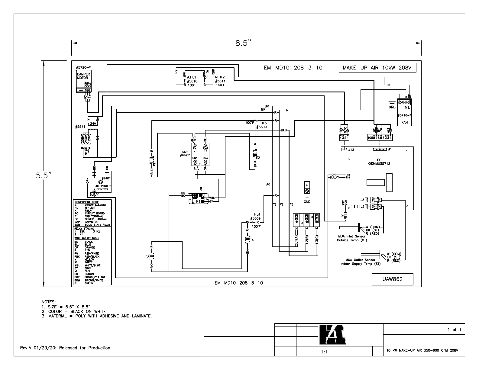
Electrical Installation
Diagrams below represent general installation requirements. Due to various model sizes available, actual
unit mechanical and wiring requirements will vary dependent upon specific model.
Low Voltage Wiring
Temperature Sensors
Two temperature sensors are included, one used to sense inlet air temperature, the other to sense supply or
outlet air temperature. Without proper installation of these probes the Make-Up Air unit will not
operate correctly.
08/14/2020 10 EI914

Control Wiring
There are two “tie-in” options available in connecting the Make-Up Air unit to a vent hood or other
venting equipment.
Option 1 – Connect an isolated “dry” switch or relay contact to the R & W terminal block (TB1).
Option 2 – Connect the supplied current transformer (CT) to terminal block (TB2)
o CT terminal block (TB2) allows for connections for up to three CT’s, for use in
Dry Type Switch Contact (Option 1)
This “on and off” control contact applied across R and W depends upon installation requirements and can
take on several possibilities:
Note: A switch closure between R & W (TB1) results in high speed blower output only.
Connection Details
Connect one side of the field provided switch to the TB1
“R” and the other side of the switch to the TB1 “W”.
NOTE: If using both Option 1 and Option 2, Option 1
(R&W) always has priority over Option 2 (CT). R&W
results in HI fan speed only.
Current Transformer (Option 2)
CT terminal block (TB2) – located on the left side of the
control module labeled “HI MED LO”. This terminal block
allows connection of up to 3 CTs, based on quantity of
exhaust sources. Please refer to the Advanced Installation
section in this manual for applications involving more than
one venting source. Connect supplied CT as shown below.
If the installation includes a multi or variable speed fan, see
the Basic Setup & Configuration section for further
details.
Standard installation:
applications where multiple venting sources are utilized
– Pressure differential switch
– CT with integrated switch (not CT provided with unit)
– Relay across exhaust blower motor
– End switch associated with exhaust damper/motor
– Room thermostat
*Switch closure across CT HI-MED-LO will not activate make-up air. Contact factory for special
wiring application.
08/14/2020 11 EI914
High Voltage Vent Hood Lighting
Note: For multi-speed vent hood installations, consideration must be made with vent
hoods that include higher wattage lighting. It is possible that the low speed trigger point
of the fan is equal to or lower than the current draw of the integrated lighting in the vent
hood itself. In this case, the CT must be installed at the motor in the vent hood minus the
lighting.
WARNING
DO NOT RETURN SOURCE POWER TO UNIT UNTIL CT SECONDARY IS TERMINATED AT
CONTROL BOARD. OPERATING THE VENT HOOD WITHOUT THE CT TERMINATED CAN
CAUSE DAMAGE TO THE CT AND A VERY HIGH SHOCK HAZARD.
Current Transformer Triggering – In order for the CT to properly
communicate external exhaust source blower motor on/off activity, it may
be necessary to provide one or more “wraps” of the power wire through the
CT.
These steps apply to all three CT paired inputs (HI, MED and LO):
1. From the external exhaust source blower motor nameplate or with actual clamp-on
current meter, note and record the external exhaust source blower motor current.
2. Depending upon the motor current, select the correct number of CT turns (see below
chart).
Motor Current CT Loops or Turns
Less than 1A 6 Wraps
2A to 3A 3 Wraps
4A to 6A 1 Wrap
Greater than 6A 0 Wraps
3. Temporarily disconnect power wire selected to feed through the CT. Depending upon the
needed turns through the CT above, either extend this wire or simply put the wire through
the CT hole as needed.
08/14/2020 12 EI914

4. Example – required three wraps, means the wire must go through the CT, loop back
around, and then loop back around the second time through before it’s terminated at its
original connection point.
5. The phasing or direction through the CT is not critical, simply one continuous wire.
6. The secondary side of the CT (pigtail wires) is connected at terminal block (TB2).
a. CT black wire, connect to either:
i. TB2-2, TB2-4 or TB2-6
b. CT red wire, connect to either:
i. TB2-1, TB2-3 or TB2-5.
Clothes Dryer Installations – When installing this product with a clothes dryer, make sure the
power wire which services both one leg of the heating element and the drum/fan motor is used.
Some dryers modulate the heating element on and off during the drying cycle which will cause
the Make-Up Air unit to shut off prematurely if the CT is installed on the power leg that services
the heating element only.
WARNING
DO NOT RETURN SOURCE POWER TO UNIT UNTIL CT SECONDARY IS TERMINATED AT
CONTROL BOARD. OPERATING THE VENT HOOD WITHOUT THE CT TERMINATED CAN
CAUSE DAMAGE TO THE CT AND A VERY HIGH SHOCK HAZARD.
Advanced Installation & Special Equipment Concerns section provides more information.
08/14/2020 13 EI914

High Voltage Wiring
Service Panel Circuit Breaker(s) Sizing – based upon unit size, the specification page shows
appropriate service size requirements based on UL and NEC code.
Note: Larger models include factory provided circuit breaker(s). This qualifies as a local
disconnect at the product.
Source Power – route and install proper current carrying conductors as per local code requirements, from
service panel. Nameplate shows current and kW rating. Use copper wire only.
Note: Single feed bus kit is available for larger models, order part number 5701.
08/14/2020 14 EI914

Basic Setup & Configuration
Control Board Configuration
Temperature Set Point – Located on the back of the control board is a dial labeled “SET POINT”. This
dial is used to set the desired output temperature.
Setting the desired output temperature is completed in three steps. See Figure 1 for temperature ranges.
Step 1 – Determine the required temperature output for the application.
o HINT: Most Make-Up Air applications suggest an output set point typically
around 50°F (10°C).
Step 2 – On the backside of the control module (hinged door) is a jumper labeled “TEMP
RANGE” (J21). This jumper allows for two temperature range options: HI or LO. Place
the jumper to select the correct range based on the determined set point (step 1).
Step 3 – using a small screwdriver, adjust the SET POINT dial according to the desired
operating temperature.
FIGURE 1
SET POINT
Switch Position
0 60 13 20 -7
1 65 16 25 -4
2 70 18 30 -1
3 75 21 35 2
4 80 24 40 4
5 85 27 45 7
6 90 29 50 10
7 95 32 55 13
NOTE: Factory default:
J21 = LO
Switch position number 6 (50°F/10°C)
HI LO
°F °C °F °C
08/14/2020 15 EI914

Fahrenheit/Celsius Selection – Labeled “°F °C” (J22). This jumper allows for selection of degrees
Fahrenheit or Celsius to be displayed on the display.
NOTE: Factory default is °F. A power down reset is required upon changing of this jumper.
Blower Speed Adjustment – the blue adjustment dial allows for fine tuning the blower speed. If you do
not need full CFM of your application and desire a larger temperature rise, the blower speed can be
reduced with this adjustment dial. However, you must realize the CFM is being reduced and you must
maintain the appropriate requirement for balancing the building inlet to the outlet mechanical driven air.
NOTE: Factory default setting is low, full counter-clockwise. To increase speed turn dial clockwise.
08/14/2020 16 EI914

Software Configuration
Software Setup Based on Specific Application – Multiple applications exist for this product. The unit is
shipped preprogrammed for a range of applications with the ability to be reprogrammed to meet others.
Below are the most prevalent applications.
Application one - single exhaust source single speed blower
Application two - multiple exhaust source blower motors of different ratings
Application three - single exhaust source multi-speed blower
Applications one and two are factory default settings and no further software setup is necessary to meet
these applications.
Applications one and two sequence:
When the CT input to CT terminal block (TB2) labeled “HI” goes active, the unit blower will go
to high speed.
o If application one, sequence ends here.
When the CT input to CT terminal block (TB2) labeled “MED” goes active, the unit blower will
go to medium speed.
When the CT input to CT terminal block (TB2) labeled “LO” goes active, the unit blower will go
to low speed.
See Nominal CFM section for typical CFM air delivery.
Application three – software configuration is required in order to activate the multi-speed functionality
of this product when being used with a multi-speed vent hood. For instruction on how to configure for
multi-speed blower interlock, see the Multi-Speed Setup section.
08/14/2020 17 EI914

SELECT
Scroll through available
options during installation
and setup.
Understanding the Product Display
DISPLAY NEXT
Select available onscreen
options during field
installation and setup.
STATUS LED
Indicates whether or not a message is available:
Solid = No message available – status good
Pulsing = Message available
Note: If pulsing, press and hold select button.
08/14/2020 18 EI914

Normal Operation Screens
Under normal operating conditions, there are two screens that may be displayed based on system activity.
Screen one – Idle screen – displayed when the unit is off.
FAN OFF
Screen two – Active screen – displayed when the unit is on.
Inlet Air Temperature
Outlet Air Temperature
IN = 30° OUT = 50°
DT = 55° CFM = HI
Desired Outlet Air
Temperature
(set point selection)
Blower Speed
(HI/MED/LO)
08/14/2020 19 EI914

Multi-Speed Setup
If your application includes a multi-speed blower, follow the setup steps in this section.
Enter into “MULTI-SPD SETUP” mode:
Press and hold “SELECT” and “NEXT” for 5 seconds
Step 1
Step 2
Step 3
Select “NEXT” to begin “MULTI-SPD SETUP”
(select HOME to return)
Turn on vent hood to its highest setting, then press “NEXT”
MULTI-SPD NEXT
HOME
SET EXT BL – HI
PRESS NEXT
FAN OFF
NOTE: If display reads:
Check CT doughnut wiring to verify it is correct, then press “NEXT”
Step 4
If vent hood has a medium speed select Y, if not select N
ERROR: 1 = 0.0A
PRESS NEXT
MED SPD Y
N
08/14/2020 20 EI914

Step 5
Step 6
Step 7
Set vent hood to medium speed “if applicable”, then press “NEXT”
SET EXT BL = MED
PRESS NEXT
If vent hood has a low speed select Y, if not select N
LO SPD Y
N
Set vent hood to low speed “if applicable”, then press “NEXT”
SET EXT BL = LO
PRESS NEXT
Step 8
Press “NEXT” after vent hood has been shut off
TURN OFF EXT BL
PRESS NEXT
08/14/2020 21 EI914

LED Monitor Lights
Green LED – is a representation of low voltage control power.
Green LED ON = good 24VAC power and fuse is in good working condition.
Green LED OFF = Fuse open or no 24VAC from transformer (or primary source breaker
open).
Red LEDs – there are 4 red LEDs on the control, each LED represents a stage of electric heating
elements.
Operational Indicators
STATUS LED
Status LED (front yellow LED) – is software driven LED which alerts the user that a message is
available in the message center.
Status LED OFF = No message is available
Status LED Blinking = Message is available
o To access available messages, the user must press and hold the “SELECT”
button for 3 seconds.
Possible messages:
Faulty sensor (OT and/or ST)
Manual hi-limit
Software hi-limit
Automatic hi-limit
See Troubleshooting section for more information on viewing available messages.
08/14/2020 22 EI914

Start Up Inspection & Observations
Entering Air Temperature: Heating is locked out when entering air temperature is greater than 55°F
(12.7°C).
Blower Delay/Control – At the end of a cycle, the blower continues to run for approximately 30 seconds
to cool off the electric elements.
Depending upon inlet temperature, outlet temperature set point, and/or larger kW unit size; a power
outage while the unit is in operation could cause the manual reset temperature limit control to open. The
reset button is located inside the control section of the cabinet.
HI-LIMIT Functionality and Operation
Level One:
Level Two:
Level Three:
Level Four: Automatic hi-limit. This is a mechanical component in series with the high voltage
Level Five:
WarmFlo temperature control regulates the output temperature based on system setup
(see Basic Setup & Configuration). See Operational Indicators section (Red LEDs)
for more information on monitoring this sequence.
Software detection of high temperature. During an active cycle, the software will
check for a value > 100°F (38°C). If a temperature > 100°F (38°C) is detected, all
electric heating elements are disabled until the supply temperature reading drops < 90°F
(32°C). The most common cause for this hi-limit is low airflow (example, dirty filter).
See Operational Indicators section (Status LED) for more information on monitoring
this sequence.
Automatic hi-limit/power relays. This is a mechanical component in the air stream
adjacent to the fan which opens a low voltage circuit to the control module upon
temperatures > 99°F (38°C) and resets upon temperatures < 85°F (29°C). Upon the
detection of this circuit being open, the control module disables the electric heating
element stages. Once this automatic hi-limit resets, the control module will then reenable the electric heating element stages. The most common cause for this hi-limit is
low airflow. See Operational Indicators section of this manual (Status LED) for more
information on monitoring this sequence.
(240V, L2 leg) to the electric heating elements and is located inside the element
chamber, top/sides. This automatic hi-limit will open at 100°F (38°C) and reset at 85°F
(29°C). The most common cause for this hi-limit is low airflow. Typically these limits
are detected monitoring current on the red wire with the use of a clamp-on amp meter.
Manual hi-limit/software detection. This is a mechanical component which opens a
low voltage circuit to the control module upon temperatures > 150°F (65°C). Upon the
detection of this circuit being open, the control module disables the electric heating
element stages. The electric heating element stages will remain disabled until the user
manually resets the limit. The manual reset limit button is located in the control box
compartment. The most common cause for this hi-limit is no blower with electric
elements due to blower failure or mechanical failure of element relays. See Operational
Indicators section of this manual (Status LED) for more information on monitoring this
sequence.
08/14/2020 23 EI914

Advanced Installation & Special Equipment Concerns
Override Electric Element Staging, “E” Tab Input – during an active call, spade terminal labeled “E”
(T7) can be jumpered to R (24VAC HOT) to bring on all four electric element stages and bypass any
temperature sensing or stage modulation functions. However, the > 55°F (12.7°C) disable still applies.
NOTE: Does not apply to models with no electric heat.
G IN (T3) Tab – Shorting this tab to “R” (24VAC HOT) at any time will cause this Make-Up Air unit to
turn on its blower (and open damper) without activating any electric heating elements.
NOTE: Blower speed upon connection of “G IN” to “R” will be low CFM blower only.
R IN NO NC –dry set of contacts (SPDT) which follows the logic of this Make-Up Air unit’s
blower/damper. The intention of this is to drive an external blower whenever this unit is activated.
Example application would be a scenario where the Make-Up Air is discharging in the return air
of a gas furnace: this contact would be used to energize the furnace blower when the Make-Up
Air is activated.
FAN ON (T5) – Special output intended to be used by factory technician only. Terminal has 24VDC, do
not use.
Multiple Exhaust Fan/Blower Installation
CT terminal block (TB2) – located on the left side of the control module labeled “HI MED LO”. This
terminal block allows connection of up to 3 CTs, based on quantity of exhaust sources.
CT monitoring the “largest” exhaust source blower motor would connect to the inputs labeled “HI”
CT monitoring the “mid-sized” exhaust source blower motor would connect to the inputs labeled “MED”
CT monitoring the “smallest” exhaust source blower motor would connect to the inputs labeled “LO”
Information: CT terminal block (TB2)
Included with this product is one CT.
o Additional CTs are available.
o Additional CTs can apply to any of the three terminal block pairs.
Use only Electro Industries’ CTs designed for this product (part #3629).
08/14/2020 24 EI914

External Damper, Field Furnished and Installed:
Preparation or Pre-Wiring Sequence
1. Power up the Make-Up Air unit.
2. Jumper “R” and “W” screw terminal block (control board upper right).
3. Fan/blower will turn on and the internal damper will open. Observe the opening of the internal
damper.
4. With the internal damper open, disconnect all three wires. Separate, do not allow the gray wire to
touch either brown or violet wires.
5. Turn off the unit power and remove jumper at “R” and “W” terminal block.
External Damper without End Switch – Select Actuator Type and Field Wires
A. 3-wire, power open/power close, 24VAC – extend the gray/violet/brown wires from the
disconnected internal damper actuator. Connect these wires to the field installed external actuator.
Gray – common
Violet – 24VAC = open
Brown – 24VAC = close
B. 2-wire, power open/spring return – extend wires from the internal damper actuator – gray and
violet. Cap off brown wire.
Gray – common
Violet – 24VAC = open
Damper with End Switch
1. Depending upon the type of actuator, select A or B above and field wire as detailed above.
2. Locate the “SB IN” or “END” tab, inside control board, lower right.
3. Connect the end switch (normally open) contacts as follows:
a. End Switch “SB IN” tab
b. End Switch “C” tab (common)
4. Pull or remove J24 peg jumper (to left of “SB IN” tab).
Sequence – with J24 open, there will be no fan or heat action until the “SB IN” tab is shorted to common.
With “SB IN” shorted to common, normal Electro Make-Up Air unit sequence begins.
08/14/2020 25 EI914

Troubleshooting
1. This product contains several interference suppression components, but as an electronic logic
product unpredictable and unusual transients or interferences may sometimes cause strange
results. If this product is “acting strange”, turn off the source power, count to 10, and reenergize.
2. Terminal blocks are clamp-down type. If there is no wire connected and the screw is loose, the
screw may not necessarily make a good electrical contact to the inside components. Example – if
you are jumpering the thermostat terminals without thermostat wire connection or if you are
attempting to measure voltage on a screw head, you may get erroneous or unpredictable results if
the screw is not tightened down.
3. Use general heating system logic information and basic understanding of the terminal block
wiring functions when measuring voltage to determine proper operation of this module.
Temperature Sensors
The inlet sensor is used to determine the incoming air temperature. The incoming air temperature
information is used in conjunction with the outlet sensor by the software to determine temperature
differential across the unit, estimated CFM, when to lockout the heating elements during mild temperature
operation, and modulate the heating elements to maintain precise temperature control.
Troubleshooting Temperature Sensors
If the message center is indicating that one of the temperature sensors is faulty, a volt-meter with DC
measuring capabilities can be used to help determine the issue.
Measuring across the red and white wires, the meter should read approximately 5 volts DC. If the reading
is 4 volts or less, there is a chance the sensor has shorted out. Disconnect the sensor from the terminal
block and recheck the voltage on the terminal block. Voltage should read 5 volts. If not, a component on
the control board itself has likely failed. If the terminal block reads 5 volts, the sensor has failed.
Temperature Sensor Detail
Red wire to J2-1 +5VDC or “RED”
Black wire to J2-2 “DATA” or “BLK”
White wire to J2-3 COM or “WHT”
Air Filter
A dirty filter can lead to poor system performance and eventual hi-limiting. It is suggested to wash filter
at least twice per year. See Routine Maintenance section of this manual for instruction on how to wash
the filter.
08/14/2020 26 EI914

Troubleshooting Solution
Display is blank and nothing
is turning on
Unit is not producing heat
Unit is not delivering
adequate warm air
temperature
The “Status LED” is
blinking
This unit includes a 2A fuse located on the control board, verify it is
in good working condition.
If 2A fuse is open, replace.
If 2A fuse is not open, check the primary and secondary side of the
transformer to ensure power is available.
If good primary and secondary voltage is detected, disconnect all
low voltage wires (not including 24VAC secondary side of
transformer) from the control module (make sure there no
load/current through any monitoring / connected CTs).
If screen is still blank, replace board.
If screen illuminates and displays “FAN OFF”, there is an
issue with low voltage wiring.
Check unit display. Display should show “FAN OFF” or
temperature screen.
If screen is blank, check 2A fuse.
If screen displays the “FAN OFF” screen, unit is not being told to
turn on.
Verify field low voltage wiring is correct
o CT or R & W
If screen displays temperature screen, compare the OUT and DT, if
ST > DT, this Make-Up Air unit will not engage the electric
elements.
Check the “message” LED. If blinking, see section labeled Start
Up Inspection & Observations – Message Center for further
instruction.
Manual reset limit may be open.
Manual reset limit switch located in control box.
Remember the heating is locked out when entering air temperature
is greater than 55°F (12.7°C). This cannot be bypassed.
Clean the filter (lack of airflow will cause the unit to reduce its
heating output).
Check the “message” LED. If blinking, see section labeled Start
Up Inspection & Observations – Message Center for further
instruction.
Verify correct system setup which includes but is not limited to the
below:
SET POINT DIAL/HI LO Jumper
CONFIGURATION DIAL
See the Setup and Programming Instructions for further setup
details
Check source amp draw to verify all elements are working correctly
See section labeled Start Up Inspection & Observations –
Message Center for further instruction.
08/14/2020 27 EI914

Troubleshooting Solution
The blower is not turning on
The blower runs in “high
speed” only
The blower runs in “MED
speed” only
The blower runs in “LOW
speed” only
Condensation or frost buildup on cabinet or ductwork
Check unit display. Display should show “FAN OFF” or
temperature screen.
If screen is blank, check 2A fuse.
If screen displays the “FAN OFF” screen, unit is not being told to
turn on.
Verify field low voltage wiring is correct
o CT or R & W
If screen displays the temperature and blower is not on, check for
power to the blower motor.
If power present, verify switch R & W IN only closure
between circuit board T18 and T19 (must be active call).
If no switch closure between T18 and T19, replace circuit
board.
If power present and switch closure detected, replace
blower.
If power is not present, check high voltage wiring.
If using the “R & W” terminals (option 1), high speed blower is the
only option.
If using CTs, ensure correct wiring of CTs, make sure high speed
blower CT only connects to the CT terminal block (TB2) “HI”
input.
If using “Multi-Spd Setup” option, verify external exhaust blower
motor is not running high speed, once verified, it is suggested you
run through the “Multi-Spd Setup” again to verify correct
programming (see Basic Setup & Configuration section).
If using CTs to turn this product on, ensure correct wiring of CTs,
make sure MED speed blower CT only connects to the CT
terminal block (TB2) “MED” input.
If using “Multi-SPD Setup” option, verify external exhaust blower
motor is not running medium speed, once verified, it is suggested
you run through the “Multi-Spd Setup” again to verify correct
programming (see Basic Setup & Configuration section).
If using CTs to turn this product on, ensure correct wiring of CTs,
make sure LOW speed blower CT only connects to the CT
terminal block (TB2) “LO” input.
If using “Multi-Spd Setup” option, verify external exhaust blower
motor is not running low speed, once verified, it is suggested you
run through the “Multi-Spd Setup” again to verify correct
programming (see Basic Setup & Configuration section).
Insulate sections of cabinet and ductwork.
Routine Maintenance
Filter – this unit includes an air filter which is a permanent and washable filter.
Suggest at least twice per year removing filter and using standard household water to back flush collected
dust/debris.
Open small door
Filter is simply held within channels
08/14/2020 28 EI914

08/14/2020 29 EI914

08/14/2020 30 EI914

08/14/2020 31 EI914

PROPRIETARY AND CONFIDENTIAL
NOTE: THE INFORMATION CONTAINED IN THIS DRAWING
IS THE SOLE PROPERTY OF ELECTRO INDUSTRIES INC.
ANY REPRODUCTION IN PART OR AS A WHOLE WITHOUT
THE WRITTEN PERMISSION OF ELECTRO INDUSTRIES
INC. IS PROHIBITED.
NAME
DRAWN
NP
CHECKED
-
DATE
01/24/20
DECAL
860
Rev A 1-24-20
EM-MG07-208-3-14
REVSTATUS
NUMBER
UAW860
DESCRIPTION
WIRING DECAL
A
Electro
Industries
Monticello, MN 55362
SCALEAPPROVED
(763)295-4138
Production

DECAL
Rev 01 12-17-19
PROPRIETARY AND CONFIDENTIAL
NOTE: THE INFORMATION CONTAINED IN THIS DRAWING
IS THE SOLE PROPERTY OF ELECTRO INDUSTRIES INC.
ANY REPRODUCTION IN PART OR AS A WHOLE WITHOUT
THE WRITTEN PERMISSION OF ELECTRO INDUSTRIES
INC. IS PROHIBITED.
NAME
DRAWN
NP
CHECKED
-
DATE
12/17/19
REVSTATUS
NUMBER
UAW861
DESCRIPTION
WIRING DECAL
01
Electro
Industries
Monticello, MN 55362
SCALEAPPROVED
(763)295-4138
Development
DECAL
Rev A 01-23-20
PROPRIETARY AND CONFIDENTIAL
NOTE: THE INFORMATION CONTAINED IN THIS DRAWING
IS THE SOLE PROPERTY OF ELECTRO INDUSTRIES INC.
ANY REPRODUCTION IN PART OR AS A WHOLE WITHOUT
THE WRITTEN PERMISSION OF ELECTRO INDUSTRIES
INC. IS PROHIBITED.
NAME
DRAWN
CRN
CHECKED
DATE
3/5/19
-
SCALEAPPROVED
STATUS
Production
Electro
Industries
Monticello, MN 55362
(763)295-4138
REV
NUMBER
UAW862
DESCRIPTION
WIRING DECAL
A

MF,MG
ME
PROPRIETARY AND CONFIDENTIAL
NOTE: THE INFORMATION CONTAINED IN THIS DRAWING
IS THE SOLE PROPERTY OF ELECTRO INDUSTRIES INC.
ANY REPRODUCTION IN PART OR AS A WHOLE WITHOUT
THE WRITTEN PERMISSION OF ELECTRO INDUSTRIES
INC. IS PROHIBITED.
NAME
DRAWN
CRN
CHECKED
DECAL
DATE
2/19/19
-
SCALEAPPROVED
Production
EM-M[E,F,G]-[05,10]-240-1-14
Electro
Industries
Monticello, MN 55362
(763)295-4138
NUMBER
DESCRIPTION
REVSTATUS
A
866
Rev A 1/24/20
UAW866
WIRING DECAL

ME
MF
PROPRIETARY AND CONFIDENTIAL
NOTE: THE INFORMATION CONTAINED IN THIS DRAWING
IS THE SOLE PROPERTY OF ELECTRO INDUSTRIES INC.
ANY REPRODUCTION IN PART OR AS A WHOLE WITHOUT
THE WRITTEN PERMISSION OF ELECTRO INDUSTRIES
INC. IS PROHIBITED.
NAME
DRAWN
CRN
CHECKED
DECAL
867
Rev A 1-23-20
EM-M[E,F][05,10]-208-3-14
DATE
2/19/19
-
SCALEAPPROVED
STATUS
Production
Electro
Industries
Monticello, MN 55362
(763)295-4138
NUMBER
UAW867
DESCRIPTION
WIRING DECAL
REV
A

MF,MG
ME
PROPRIETARY AND CONFIDENTIAL
NOTE: THE INFORMATION CONTAINED IN THIS DRAWING
IS THE SOLE PROPERTY OF ELECTRO INDUSTRIES INC.
ANY REPRODUCTION IN PART OR AS A WHOLE WITHOUT
THE WRITTEN PERMISSION OF ELECTRO INDUSTRIES
INC. IS PROHIBITED.
NAME
DRAWN
BAS
CHECKED
DECAL
868
Rev J 1-24-20
EM-M[E,F,G]-14-208-3-14
DATE
5/5/14
-
SCALEAPPROVED
Electro
Industries
Monticello, MN 55362
(763)295-4138
Production
REVSTATUS
NUMBER
UAW868
DESCRIPTION
WIRING DECAL
J

DECAL
869
Rev J 1-23-20
PROPRIETARY AND CONFIDENTIAL
NOTE: THE INFORMATION CONTAINED IN THIS DRAWING
IS THE SOLE PROPERTY OF ELECTRO INDUSTRIES INC.
ANY REPRODUCTION IN PART OR AS A WHOLE WITHOUT
THE WRITTEN PERMISSION OF ELECTRO INDUSTRIES
INC. IS PROHIBITED.
NAME
DRAWN
BAS
CHECKED
DATE
10/1/13
-
SCALEAPPROVED
STATUS
Production
Electro
Industries
Monticello, MN 55362
(763)295-4138
MAKE UP AIR II 22kW
NUMBER
UAW869
DESCRIPTION
REV
J
WIRING DECAL

DECAL + TITLEBLOCK DO NOT PRINT AS DECAL

DECAL + TITLEBLOCK DO NOT PRINT AS DECAL

E
lectro Industries, Inc. Residential
Limited Product Warranty
Effective November 1, 2009
Electro Industries, Inc. warrants to the original owner, at the original installation site, for a period of two (2)
years from date of original purchase, that the product and product parts manufactured by Electro
Industries, Inc. are free from manufacturing defects in materials and workmanship, when used under
normal conditions and when such product has not been modified or changed in any manner after leaving
the plant of Electro Industries, Inc. If any product or product parts manufactured by Electro Industries,
Inc. are found to have manufacturing defects in materials or workmanship, such will be repaired or
replaced by Electro Industries, Inc. Electro Industries, Inc., shall have the opportunity to directly, or
through its authorized representative, examine and inspect the alleged defective product or product parts.
Electro Industries, Inc. may request that the materials be returned to Electro Industries, Inc. at owner’s
expense for factory inspection. The determination as to whether product or product parts shall be
repaired, or in the alternative, replaced, shall be made by Electro Industries, Inc. or its authorized
representative.
Electro Industries, Inc. will cover labor costs according to the Repair / Replacement Labor Allowance
Schedule for a period of ninety (90) days from the date of original purchase, to the original owner, at the
original installation site. The Repair / Replacement Labor Allowance is designed to reduce the cost of
repairs. This Repair / Replacement Labor Allowance may not cover the entire labor fee charged by your
dealer / contractor.
TWENTY YEAR (20) LIMITED WARRANTY ON BOILER ELEMENTS AND VESSELS
Electro Industries, Inc. warrants that the boiler elements and vessels of its products are free from defects
in materials and workmanship through the twentieth year following date of original purchase. If any boiler
elements or vessels are found to have a manufacturing defect in materials or workmanship, Electro
Industries, Inc. will replace them.
TWENTY YEAR (20) LIMITED WARRANTY ON SPIN FIN ELEMENTS
Electro Industries, Inc. warrants that the spin fin elements of its products are free from defects in materials
and workmanship through the twentieth year following date of original purchase. If any spin fin elements
are found to have a manufacturing defect in materials or workmanship, Electro Industries, Inc. will replace
them.
FIVE YEAR (5) LIMITED WARRANTY ON OPEN WIRE ELEMENTS
Electro Industries, Inc. warrants that the open wire elements of its products are free from defects in
materials and workmanship through the fifth year following date of original purchase. If any open wire
elements are found to have a manufacturing defect in materials or workmanship, Electro Industries, Inc.
will replace them.
Page 1 of 2 XX017

CONDITIONS AND LIMITATIONS:
1. This warranty is limited to residential, single family dwelling installations only. Any commercial or multi-unit
dwelling installations fall under the Electro Industries Commercial Limited Product Warranty.
2. Electro Industries, Inc. shall n ot be lia ble for performance related issues resulting from improper installation,
improper sizing, improper duct or distribution system, or any other installation deficiencies.
3. If at the time of a request for service the original owner cannot provide an original sales receipt or a warranty
card registration then the warranty period for the product will have deemed to begin the date the product is
shipped from the factory and NOT the date of original purchase.
4. The product must have been sold and installed by a licensed electrician, plumbing, or heating contractor.
5. The application and installation of the product must be in compliance with Electro Industries, Inc. specifications,
as stated in the installation and instruction manual, and all state, provincial and federal codes an d statutes. If
not, the warranty will be null and void.
6. The purchaser shall have maintained the product in accordance with the manual that accompanies the unit.
Annually, a qualified and licensed contractor must inspect the product to assure it is in proper working condition.
7. All related heating components must be maintained in good operating condition.
8. All lines must be checked to confirm that all condensation drains properly from the unit.
9. Replacement of a product or product part under this limited warranty does not extend the warranty term or
period.
10. Replacement product parts are warranted to be free from defects in material and workmanship for ninety (90)
days from the date of installation. All exclusions, conditions, and limitations expressed in this warranty apply.
11. Before warranty claims will be honored, Electro Industries, Inc. shall have t he opportunity to directly, or through
its authorized representative, examine and inspect the alleged defective product or product parts. Remedies
under this warranty are limited to repairing or replacing alleged defective pr oduct or product parts. The decision
whether to repair or, in the alternative, replace products or product parts shall be made by Electro Industries, Inc.
or its authorized representative.
THIS WARRANTY DOES NOT COVER:
1. Costs for labor for diagnosis, removal or reinstallation of an alleged defective product or product part,
transportation to Electro Industries, Inc., and any other materials necessary to perform the exchange, except as
stated in this warranty. Replacement material will be invoiced to the distributor in the usual manner an d will be
subject to adjustment upon verification of defect.
2. Any product or product part that has been da maged as a result of being improperly serviced or operated,
including, but not limited to, the following: operated during construction phase, with insufficient water or air flow;
allowed to freeze; subjected to flood conditions; subjected to improper voltages or power supplies; operated with
air flow or water conditions and/or fuels or additives which cause unusual deposits or corrosion in or on the
product; chemical or galvanic erosion; improper maintenance or subject to any other abuse or negligence.
3. Any product or product part that has been damaged as a result of natural disasters, including, but not limited to,
lightning, fire, earthquake, hurricanes, tornadoes or floods.
4. Any product or prod uct part that has been damaged as a result of shipment or handling by the freight carrier. It
is the receiver’s responsibility to claim and process freight damage with the carrier.
5. Any product or prod uct part that has been defaced, abused or suffered unusual wear and tear as determined by
Electro Industries, Inc. or its authorized representative.
6. Workmanship of any installer of the product or product part. This warranty does not assume any liability of any
nature for unsatisfactory performance caused by improper installation.
7. Transportation charges for any replacement product, product part or component, service calls, normal
maintenance; replacement of fuses, filters, refrigerant, etc.
THESE WARRANTIES DO NOT EXTEND TO ANYONE EXCEPT THE ORIGINAL PURCHASER AT RETAIL AND ONLY WHEN THE PRODUCT IS
IN THE ORIGINAL INSTALLATION SITE. THE REMEDIES SET FORTH HEREIN ARE EXCLUSIVE.
ALL IMPLIED WARRANTIES, INCLUDING WARRANTIES OF MERCHANTABILITY AND FITNESS FOR A PARTICULAR PURPOSE, ARE
HEREBY DISCLAIMED WITH RESPECT TO ALL PURCHASERS OR OWNERS. ELECTRO INDUSTRIES, INC. IS NOT BOUND BY PROMISES
MADE BY OTHERS BEYOND THE TERMS OF THESE WARRANTIES. FAILURE TO RETURN THE WARRANTY CARD SHALL HAVE NO
EFFECT ON THE DISCLAIMER OF THESE IMPLIED WARRANTIES.
ALL EXPRESS WARRANTIES SHALL BE LIMITED TO THE DURATION OF THIS EXPRESS LIMITED WARRANTIES SET FORTH HEREIN AND
EXCLUDE ANY LIABILITY FOR CONSEQUENTIAL OR INCIDENTAL DAMAGES RESULTING FROM THE BREACH THEREOF. SOME STATES
OR PROVINCES DO NOT ALLOW THE EXCLUSION OR LIMITATION OF INCIDENTAL OR CONSEQUENTIAL DAMAGES, SO THE ABOVE
LIMITATIONS OR EXCLUSIONS MAY NOT APPLY. PRODUCTS OR PARTS OF OTHER MANUFACTURERS ATTACHED ARE SPECIFICALLY
EXCLUDED FROM THE WARRANTY.
THIS WARRANTY GIVES YOU SPECIFIC LEGAL RIGHTS, AND YOU MAY HAVE OTHER RIGHTS WHICH VARY UNDER THE LAWS OF EACH
STATE. IF ANY PROVISION OF THIS WARRANTY IS PROHIBITED OR INVALID UNDER APPLICABLE STATE OR PROVINCIAL LAW, THAT
PROVISION SHALL BE INEFFECTIVE TO THE EXTENT OF THE PROHIBITION OR INVALIDITY WITHOUT INVALIDATING THE REMAINDER OF
THE AFFECTED PROVISION OR THE OTHER PROVISIONS OF THIS WARRANTY.
Page 2 of 2 XX017
 Loading...