

Page 1
MAKEVMA501
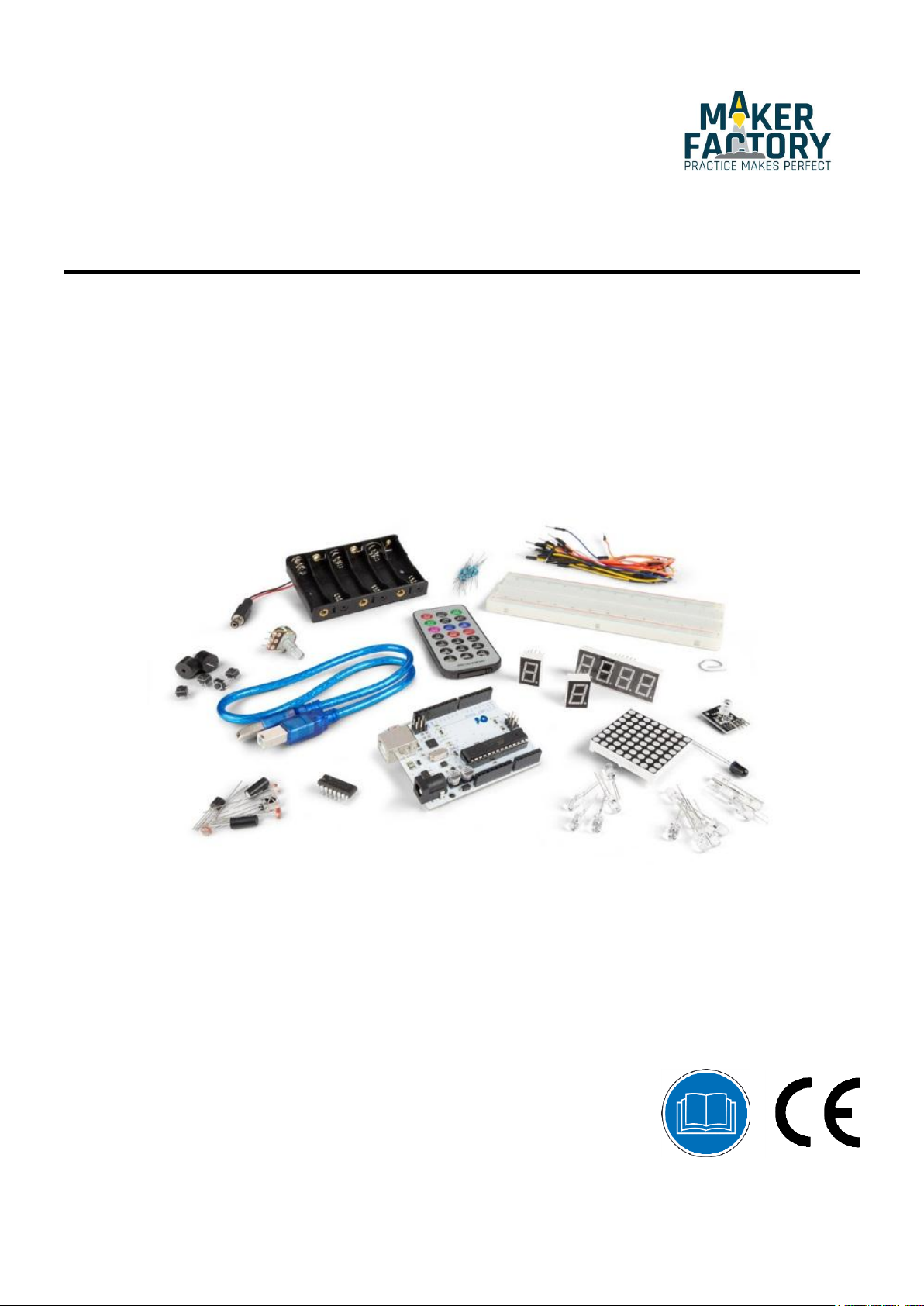
DIY STARTER KI T FOR ARDUINO®
USER MANUAL
Page 2
MAKEVMA501
This device can be used by children aged from 8 years and above, and persons with
reduced physical, sensory or mental capabilities or lack of experience and knowledge if
they have been given supervision or instruction concerning the use of the device in a
safe way and understand the hazards involved. Children shall not play with the device.
Cleaning and user maintenance shall not be made by children without supervision.
Indoor use only.
Keep away from rain, moisture, splashing and dripping liquids.
Familiarise yourself with the functions of the device before actually using it.
All modifications of the device are forbidden for safety reasons. Damage caused by user
modifications to the device is not covered by the warranty.
Only use the device for its intended purpose. Using the device in an unauthorised way
will void the warranty.
Damage caused by disregard of certain guidelines in this manual is not covered by the
warranty and the dealer will not accept responsibility for any ensuing defects or
problems.
The dealers cannot be held responsible for any damage (extraordinary, incidental or
indirect) – of any nature (financial, physical…) arising from the possession, use or
failure of this product.
Due to constant product improvements, the actual product appearance might differ from
the shown images.
Product images are for illustrative purposes only.
Do not switch the device on immediately after it has been exposed to changes in
temperature. Protect the device against damage by leaving it switched off until it has
reached room temperature.
Keep this manual for future reference.
USER MANUAL
1. Introduction
To all residents of the European Union
Important environmental information about this product
This symbol on the device or the package indicates that disposal of the device after its lifecycle could
harm the environment. Do not dispose of the unit (or batteries) as unsorted municipal waste; it should
be taken to a specialized company for recycling. This device should be returned to your distributor or to
a local recycling service. Respect the local environmental rules.
If in doubt, contact your local waste disposal authorities.
Please read the manual thoroughly before bringing this device into service. If the device was damaged in
transit, do not install or use it and contact your dealer.
2. Safety Instructions
3. General Guidelines
4. What is Arduino
Arduino® is an open-source prototyping platform based in easy-to-use hardware and software. Arduino® boards
are able to read inputs – light-on sensor, a finger on a button or a Twitter message – and turn it into an output
– activating of a motor, turning on an LED, publishing something online. You can tell your board what to do by
sending a set of instructions to the microcontroller on the board. To do so, you use the Arduino programming
language (based on Wiring) and the Arduino® software IDE (based on Processing).
Surf to www.arduino.cc and www.arduino.org for more information.
V. 01 – 08/11/2017 2
®
Page 3
MAKEVMA501
MAKEVMA100
The MAKEVMA100 (Arduino® Uno compatible) is a microcontroller board based on the ATmega328. It has 14
digital input/output pins (of which 6 can be used as PWM outputs), 6 analogue inputs, a 16 MHz ceramic
resonator, a USB connection, a power jack, an ICSP header and a reset button. It contains everything needed
to support the microcontroller. Connect it to a computer with a USB cable or power it with an AC-to-DC
adapter or battery to get started.
5. Contents
1 x ATmega328 UNO DEVELOPMENT BOARD (MAKEVMA100)
15 x LED (different colors)
8 x 220 Ω resistor (RA220E0)
5 x 1k resistor (RA1K0)
5 x 10k resistor (RA10K0)
1 x 830 hole breadboard
1 x RGB LED module (MAKEVMA318)
4 x 4-pin Key switch
1 x active buzzer (MAKEVMA319)
1 x passive buzzer
1 x 1838 IR infrared 37.9 kHz receiver (MAKEVMA317)
1 x infrared remote control
1 x infrared sensor diode
1 x LM35 temperature sensor (LM35DZ)
2 x ball tilt switch (similar to MERS4 & MERS5)
3 x photosensitive resistor LDR (similar to LDR04)
1 x 74HC595 shift register (HC595)
1 x battery holder for 6 AA batteries (similar to BH363B)
1 x 8*8 LED matrix display
1 x single-digit 7-segment LED display
1 x 4-digit 7-segment LED display
30 x breadboard jumper wire
1 x USB cable
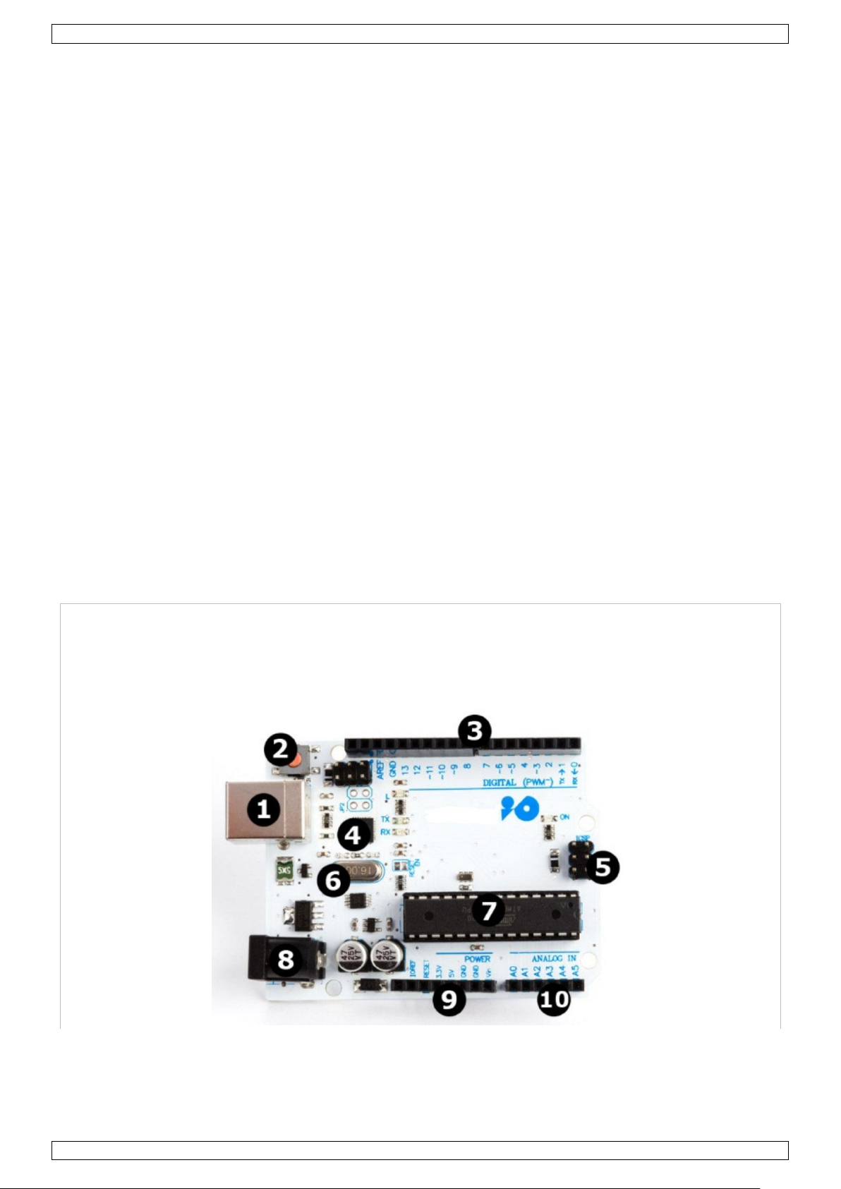
6. The ATmega328
V. 01 – 08/11/2017 3
Page 4
MAKEVMA501
1
USB interface
6 16 MHz clock
2
reset button
7 Atmel mega328p (DIL)
3
digital I/O
8 7-12 VDC power input
4
Atmel mega16U2
9 power and ground pins
5
ICSP
10
analogue input pins
microcontroller .................................................................................................. ATmega328
operating voltage ....................................................................................................... 5 VDC
input voltage (recommended) ................................................................................ 7-12 VDC
input voltage (limits) ............................................................................................. 6-20 VDC
digital I/O pins ................................................................ 14 (of which 6 provide PWM output)
analogue input pins ........................................................................................................... 6
DC current per I/O pin ............................................................................................... 40 mA
DC current for 3.3 V pin ............................................................................................. 50 mA
flash memory ...................................... 32 kB (ATmega328) of which 0.5 kB used by bootloader
SRAM .................................................................................................... 2 kB (ATmega328)
EEPROM.................................................................................................. 1 kB (ATmega328)
clock speed ............................................................................................................. 16 MHz
dimensions
length .............................................................................................................. 68.6 mm
width ............................................................................................................... 53.4 mm
weight ................................................................................................................... 25 g
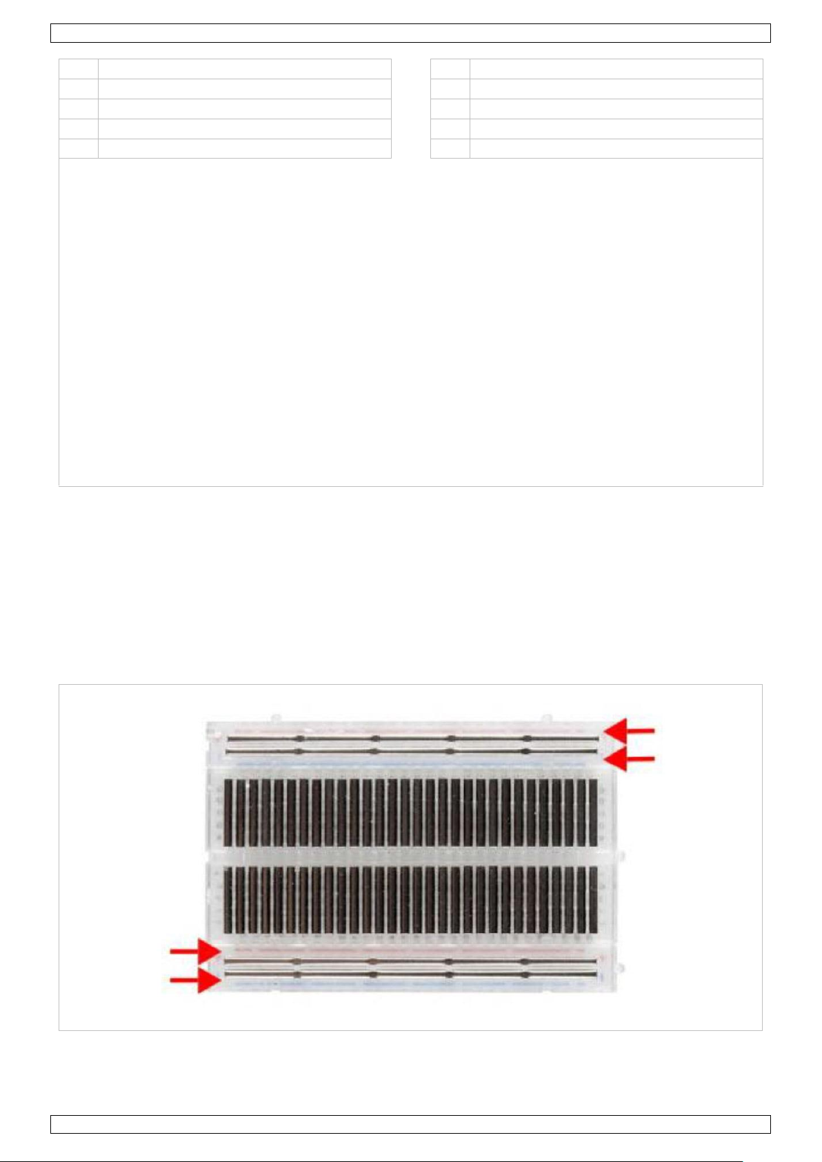
Power rails.
7. Operation
7.1 The Breadboard
Breadboards are one of the most fundamental pieces when learning how to build circuits. In this tutorial, we
will introduce you to what breadboards are and how they work.
Let us look at a larger, more typical breadboard. Aside from the horizontal rows, breadboards have what are
called power rails that run vertically along the sides.
V. 01 – 08/11/2017 4
Page 5
MAKEVMA501
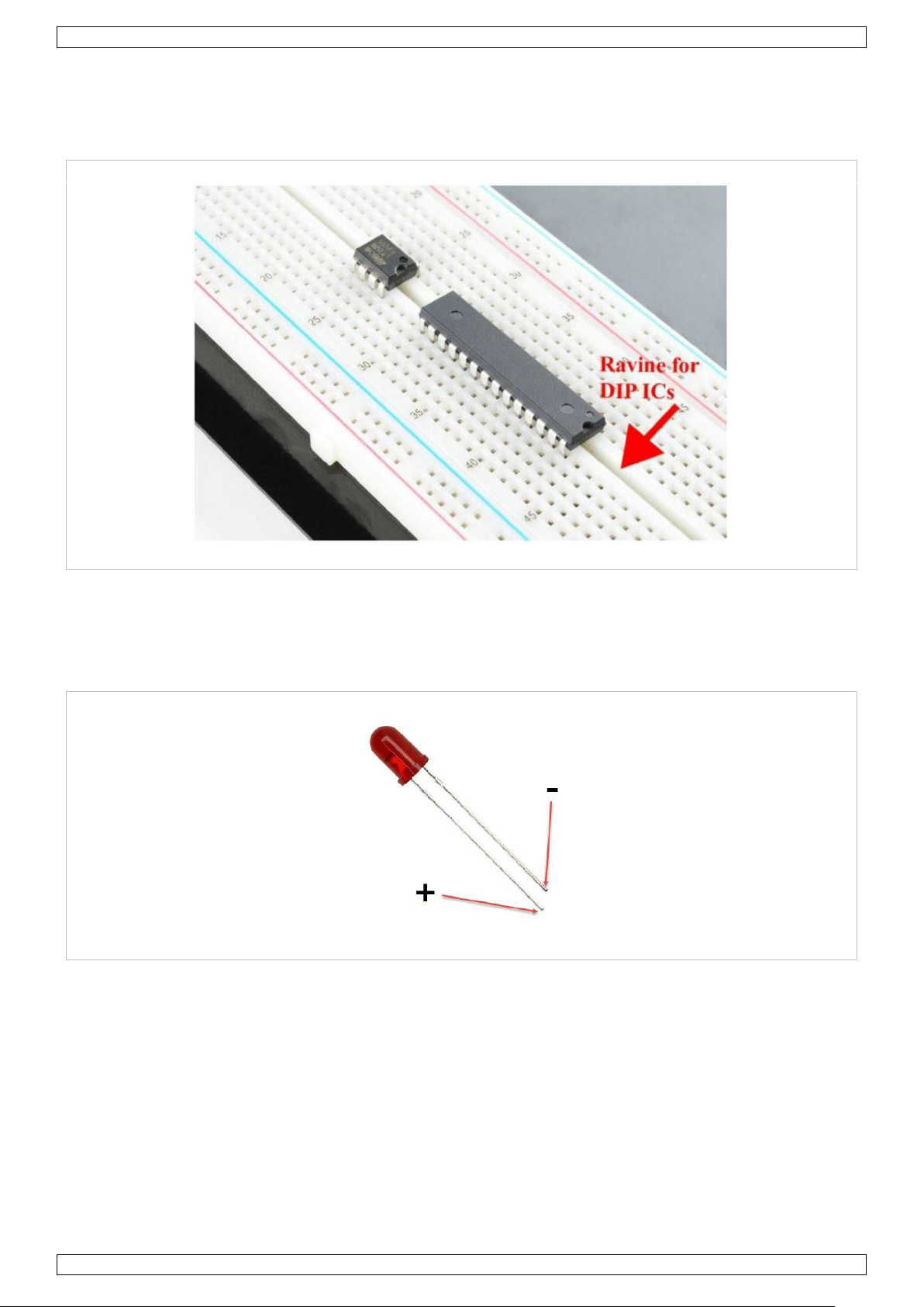
Ravine.
Chips have legs that come out of both sides and fit perfectly over the ravine. Since each leg on the IC is
unique, we do not want both sides to be connected to each other. That is where the separation in the middle of
the board comes in handy. Thus, we can connect components to each side of the IC without interfering with the
functionality of the leg on the opposite side.
7.2 A Blinking LED
Let’s start with a simple experiment. We are going to connect an LED to one of the digital pins rather than
using LED13, which is soldered to the board.
Required Hardware
1 x red M5 LED
1 x 220 Ω resistor
1 x breadboard
jumper wires as needed
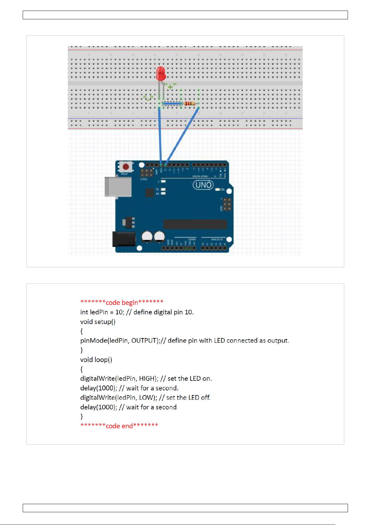
Follow the diagram below. We are using digital pin 10, and connecting the LED to a 220 Ω resistor to avoid
high-current damaging the LED.
V. 01 – 08/11/2017 5
Page 6
MAKEVMA501
Connection
Programming Code
Result
After programming, you will see the LED connected to pin 10 blinking, with an interval of approximately one
second. Congratulations, the experiment is now successfully completed!
V. 01 – 08/11/2017 6
Page 7
MAKEVMA501
7.3 PWM Gradational LED
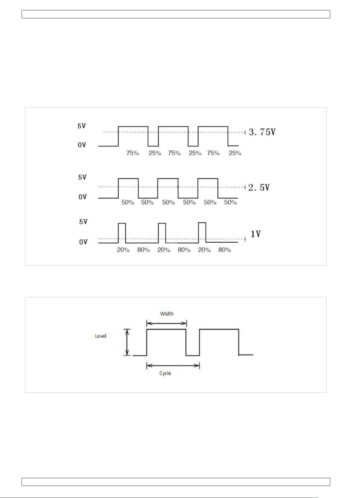
PWM (Pulse Width Modulation) is a technique used to encode analogue signal levels into digital ones. A
computer cannot output analogue voltage but only digital voltage values. So, we will be using a high-resolution
counter to encode a specific analogue signal level by modulating the duty cycle of PWM. The PWM signal is also
digitalized because in any given moment, fully on DC power is either 5 V (on) of 0 V (off). The voltage or
current is fed to the analogue load (the device using the power) by repeated pulse sequence being on or off.
Being on, the current is fed to the load; being off, it is not. With the adequate bandwidth, any analogue value
can be encoded using PWM. The output voltage value is calculated via the on and off time.
output voltage = (turn on time/pulse time) * maximum voltage value
PWM has many applications: lamp brightness regulation, motor speed regulation, sound making, etc. The
following are the basic parameters of PWM:
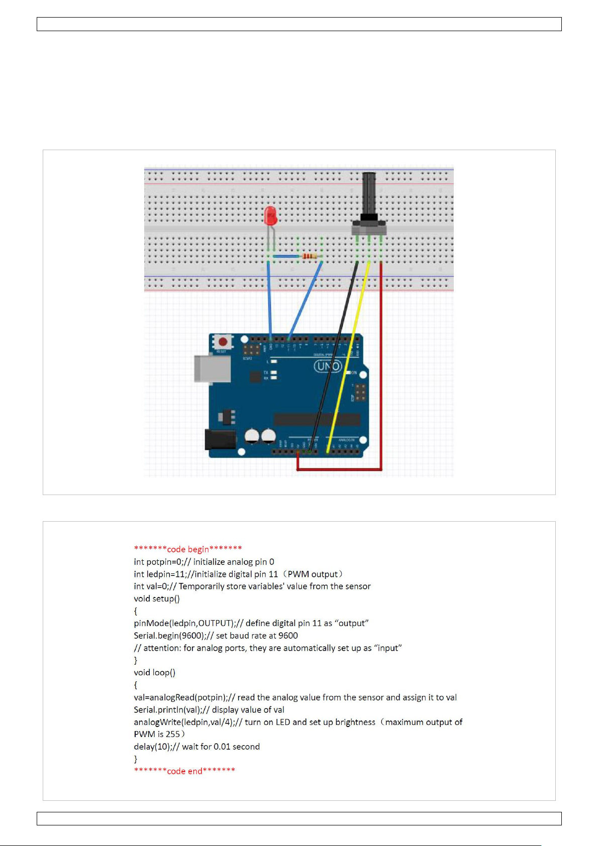
There are six PQM interfaces on Arduino®, namely digital pin, 3, 5, 6, 9, 10 and 11. In this experiment, we will
be using a potentiometer to control the LED brightness.
V. 01 – 08/11/2017 7
Page 8
MAKEVMA501
Required Hardware
1 x variable resistor
1 x red M5 LED
1 x 220 Ω resistor
1 x breadboard
jumper wires as needed
Connection
Programming Code
V. 01 – 08/11/2017 8
Page 9
MAKEVMA501
red Vf .............................................................................................................. 1.8 to 2.1 V
green Vf ........................................................................................................... 3.0 to 3.2 V
blue Vf ............................................................................................................. 3.0 to 3.2 V
red colour ........................................................................................................ 620-625 nm
green colour ..................................................................................................... 520-525 nm
blue colour ....................................................................................................... 465-470 nm
red brightness @ 20 mA ................................................................................... 600-800 mcd
green brightness @ 20 mA .............................................................................. 800-1000 mcd
blue brightness @ 20 mA .............................................................................. 1500-2000 mcd
Pin Name
Description
R
red
G
green
B
blue
-
GND
In this code, we are using the analogWrite (PWM interface, analogue value) function. We will read the analogue
value of the potentiometer and assign the value to PWM port, so there will be corresponding change to the
brightness of the LED. One final part will be displaying the analogue value on the screen. You can consider this
as the analogue value reading project adding the PWM analogue value assigning part.
Result
After programming, rotate the potentiometer knob to see changes of the displaying value. Also, note the
obvious change of brightness on the breadboard.
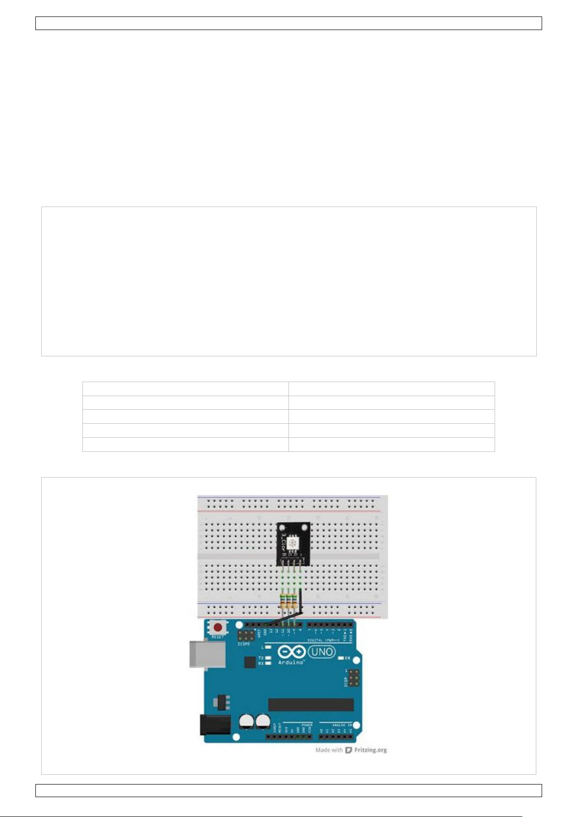
7.4 RGB LED Module
The RGB LED module is a full-colour LED allows for cool lighting effects.
Specifications
Pin Layout
Connection
V. 01 – 08/11/2017 9
Page 10

MAKEVMA501
Programming Code
V. 01 – 08/11/2017 10
Page 11

MAKEVMA501
7.5 The Active Buzzer
An active buzzer is widely used on computers, printers, alarms, etc. as a sound-making element. It has an
inner vibration source. Simply connect it with a 5 V power supply to make it buzz constantly.
Required Hardware
1 x buzzer
1 x key
1 x breadboard
jumper wires as needed
V. 01 – 08/11/2017 11
Page 12

MAKEVMA501
Connection
Programming Code
Result
After programming, the buzzer should ring.
V. 01 – 08/11/2017 12
Page 13

MAKEVMA501
7.6 The Photosensitive Resistor
A photoresistor is a resistor whose resistance varies according to different light strengths. It is based on the
photoelectric effect of a semiconductor. If the incident light is intense, the resistance reduces; if the incident
light is weak, the resistant increases. A photovaristor is commonly applied in the measurement of light, light
control and photovoltaic conversion.
Let’s start with a relative simple experiment. The photovaristor is an element that changes its resistance as
light strength changes. Refer to the PWM experiment, replacing the potentiometer with a photovaristor. When
there is a change in light strength, there will be a corresponding change on the LED.
Required Hardware
1 x photoresistor
1 x red M5 LED
1 x 10KΩ resistor
1 x 220 Ω resistor
1 x breadboard
jumper wires as needed
Connection
V. 01 – 08/11/2017 13
Page 14

MAKEVMA501
Programming Code
Result
After programming, change the light strength around the photovaristor and observe the LED changing!
7.7 The Flame Sensor
A flame sensor (IR receiving diode) is specifically used on robots to find the fire source. This sensor is highly
sensitive to flames.
A flame sensor has a specifically designed IR tube to detect fire. The brightness of the flames will then be
converted to a fluctuating level signal. The signals are the input into the central processor.
Required Hardware
1 x flame sensor
1 x buzzer
1 x 10KΩ resistor
1 x breadboard
jumper wires as needed
V. 01 – 08/11/2017 14
Page 15

MAKEVMA501
Connection
Connect the negative to the 5 V pin and the positive to the resistor. Connect the other end of the resistor to
GND. Connect one end of a jumper wire to a clip, which is electrically connected to sensor positive, the other
end to the analogue pin.
Programming Code
V. 01 – 08/11/2017 15
Page 16

MAKEVMA501
7.8 The LM35 Temperature Sensor
The LM35 is a common and easy-to-use temperature sensor. It does not require other hardware, you just need
an analogue port to make it work. The difficulty lies in compiling the code to convert the analogue value it
reads to Celsius temperature.
Required Hardware
1 x LM35 sensor
1 x breadboard
jumper wires as needed
Connection
V. 01 – 08/11/2017 16
Page 17

MAKEVMA501
Programming Code
Result
After programming, open the monitoring window to see the current temperature.
7.9 The Tilt Sensor Switch
A tilt sensor will detect orientation and inclination. They are small, low power and easy-to-use. If used properly,
they will not wear out. Their simplicity makes them popular for toys, gadgets and other appliances. They are
referred to as mercury, tilt or rolling ball switches.
The Simple Tilt-Activated LED
This is the most basic connection of a tilt switch, but can be a handy while one is learning about them. Simply
connect in series with an LED, resistor and battery.
Reading the Switch State with a Microcontroller
The layout below shows a 10K pull-up resistor. The code states the built-in pull-up resistor that you can turn on
by setting an input pin to the high output. If you use the internal pull-up you can skip the external one.
V. 01 – 08/11/2017 17
Page 18

MAKEVMA501
Programming Code
V. 01 – 08/11/2017 18
Page 19

MAKEVMA501
7.10 The IR Receiver
Infrared communication is a common, inexpensive and easy-to-use wireless communication technology. IR light
is very similar to visible light, except that it has a slightly longer wavelength. This means that IR is
undetectable to the human eye – perfect for wireless communication. Example: When you hit a button on your
TV remote, an IR LED repeatedly turns on and off, 38000 times a second, to transmit information to an IR
photo sensor on your TV.
Connection
V. 01 – 08/11/2017 19
Page 20

MAKEVMA501
Programming Code
7.11 One-Digit Seven-Segment Display
LED segment displays are common for displaying numerical information. They are widely applied on displays of
ovens, washing machines, etc. the LED segment display is a semiconductor light-emitting device. Its basic unit
is an LED (light-emitting diode). Segment displays can be divided into 7-segment and 8-segment displays.
According to the wiring method, LED segment displays can be divided into displays with common anode and
displays with common cathode. Common anode displays refer to displays that combine all the anodes of the
LED units into one common anode (COM).
V. 01 – 08/11/2017 20
Page 21

MAKEVMA501
For the common anode display, connect the common anode (COM) to +5 V. When the cathode level of a certain
segment is low, the segment is on; when the cathode level of a certain segment is high, the segment is off. For
the common cathode display, connect the common cathode (COM) to GND. When the anode level of a certain
segment is high, the segment is on; when the anode level of a certain segment is low, the segment is off.
Connection
Programming Code
V. 01 – 08/11/2017 21
Page 22

MAKEVMA501
7.12 Four-Digit Seven-Segment Display
V. 01 – 08/11/2017 22
Page 23

MAKEVMA501
Connection
Programming Code
This is an example of how to drive a 7-segment LED display without the use of current limiting resistors.
This technique is very common but requires some knowledge of electronics – you do run the risk of dumping
too much current through the segments and burning out parts of the display. If you use the stock code you
should be ok, but be careful editing the brightness values.
This code should work with all colours (red, blue, yellow, green) but the brightness will vary from one colour to
the next because the forward voltage drop of each colour is different. This code was written and calibrated for
the red colour.
V. 01 – 08/11/2017 23
Page 24

MAKEVMA501
V. 01 – 08/11/2017 24
Page 25

MAKEVMA501
V. 01 – 08/11/2017 25
Page 26

MAKEVMA501
V. 01 – 08/11/2017 26
Page 27

MAKEVMA501
V. 01 – 08/11/2017 27
Page 28

MAKEVMA501
V. 01 – 08/11/2017 28
Page 29

MAKEVMA501
7.13 8x8 LED Matrix
With low-voltage scanning, LED dot-matrix displays have advantages such as power saving, long service life,
low cost, high brightness, wide angle of view, long visual range, being waterproof… LED dot-matrix displays can
meet the needs of different applications and thus have a broad development prospect.
The 8*8 dot-matrix is made up of sixty-four LEDs, and each LED is placed at the cross point of a row and a
column. When the electrical level of a certain row is 1 and the electrical level of a certain column is 0, the
corresponding LED will light up. If you want to light the LED on the first dot, you should set pin 9 to high level
and pin 13 to low level. If you want to light LEDs on the first row, you should set pin 9 to high level and pins
13, 3, 4, 10, 6, 11, 15 and 16 to low level. If you want to light the LEDs on the first column, set pin 13 to low
level and pins 9, 14, 8, 12, 1, 7, 2 and 5 to high level.
Connection
V. 01 – 08/11/2017 29
Page 30

MAKEVMA501
Programming Code
© COPYRIGHT NOTICE
All worldwide rights reserved. No part of this manual may be copied, reproduced, translated or reduced to
any electronic medium or otherwise without the prior written consent of the copyright holder.
V. 01 – 08/11/2017 30
 Loading...