

Page 1
MAKEVMA409
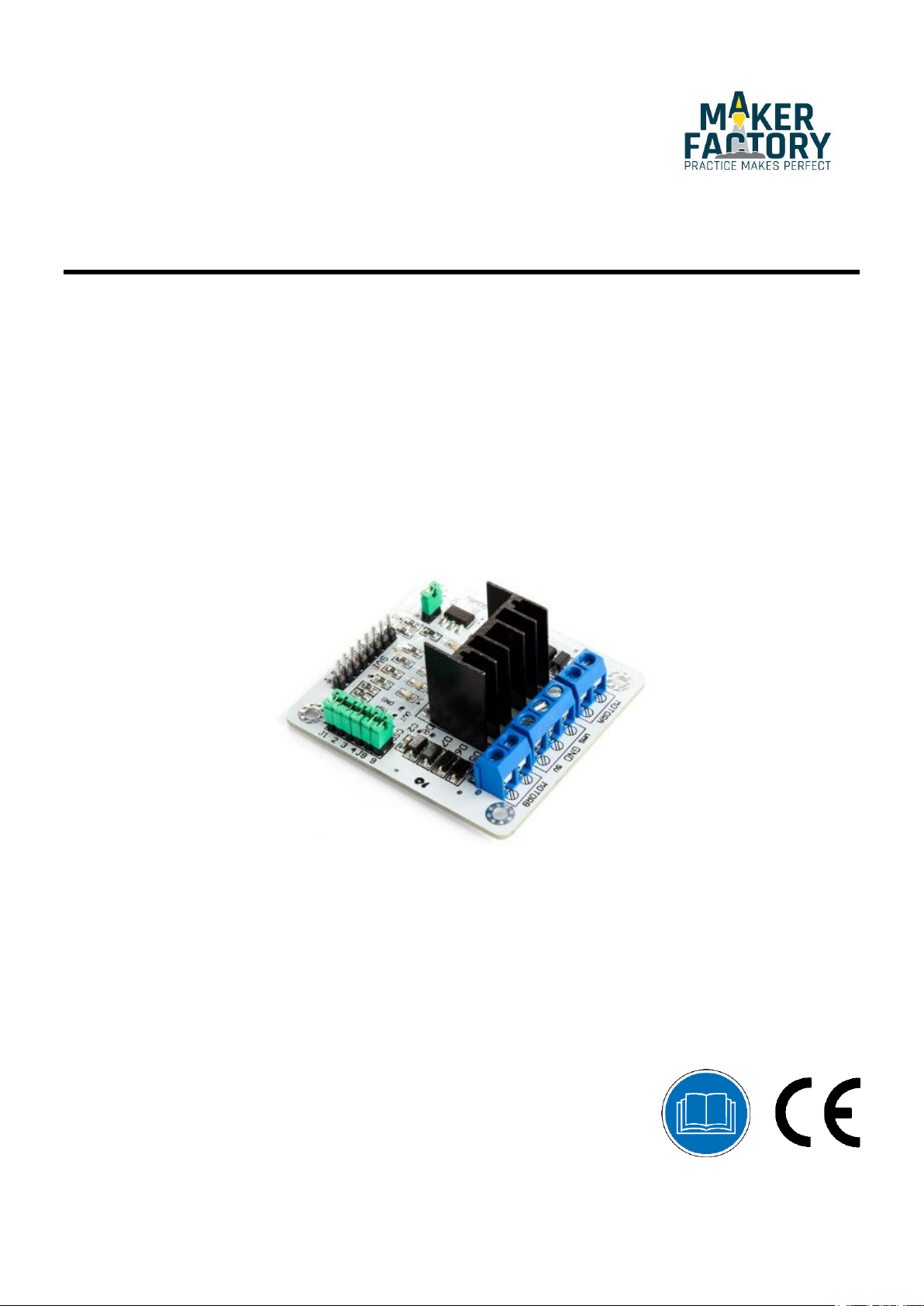
L298N DUAL BRIDGE DC S TEPPER CONTROLLER BOARD
USER MANUAL
Page 2
MAKEVMA409
This device can be used by children aged from 8 years and above, and persons with
reduced physical, sensory or mental capabilities or lack of experience and knowledge if
they have been given supervision or instruction concerning the use of the device in a
safe way and understand the hazards involved. Children shall not play with the device.
Cleaning and user maintenance shall not be made by children without supervision.
Indoor use only.
Keep away from rain, moisture, splashing and dripping liquids.
Familiarise yourself with the functions of the device before actually using it.
All modifications of the device are forbidden for safety reasons. Damage caused by user
modifications to the device is not covered by the warranty.
Only use the device for its intended purpose. Using the device in an unauthorised way
will void the warranty.
Damage caused by disregard of certain guidelines in this manual is not covered by the
warranty and the dealer will not accept responsibility for any ensuing defects or
problems.
The dealers cannot be held responsible for any damage (extraordinary, incidental or
indirect) – of any nature (financial, physical…) arising from the possession, use or
failure of this product.
Due to constant product improvements, the actual product appearance might differ from
the shown images.
Product images are for illustrative purposes only.
Do not switch the device on immediately after it has been exposed to changes in
temperature. Protect the device against damage by leaving it switched off until it has
reached room temperature.
Keep this manual for future reference.
USER MANUAL
1. Introduction
To all residents of the European Union
Important environmental information about this product
This symbol on the device or the package indicates that disposal of the device after its lifecycle could
harm the environment. Do not dispose of the unit (or batteries) as unsorted municipal waste; it should
be taken to a specialized company for recycling. This device should be returned to your distributor or to
a local recycling service. Respect the local environmental rules.
If in doubt, contact your local waste disposal authorities.
Please read the manual thoroughly before bringing this device into service. If the device was damaged in
transit, do not install or use it and contact your dealer.
2. Safety Instructions
3. General Guidelines
V. 01 – 08/11/2017 2
Page 3

MAKEVMA409
MAKEVMA409
This module allows full control of two DC motors or one stepper motor.
driver ................................................................................................................... L298N
driver power supply ..................................................................................... +5 V to +35 V
driver output current (max.) ......................................................................................... 2 A
logic power output Vss ................................................... +5 V to +7 V (internal supply +5 V)
logic current ........................................................................................................ 0-36 mA
controlling level ............................................................ low: -0.3 V to 1.5 V, high: 2.3 V-Vss
enable signal level ........................................................ low: -0.3 V to 1.5 V, high: 2.3 V-Vss
max. power .............................................................................................................. 25 W
working temperature .............................................................................. -25 °C to +130 °C
dimensions ............................................................................................. 69 x 56 x 36 mm
Pin Name
Description
MOTORA
motor 1
MOTORB
motor 2
VMS
5 VDC to 35 VDC
GND
ground
5V
power input for the logic circuit on the board
ENA
enable pin for motor 1
IN1
control pin motor 1
IN2
control pin motor 1
IN3
control pin motor 1
IN4
control pin motor 1
ENB
enable pin for motor 2
5V
5 V output
GND
ground
CSB
current test pin for motor 1; can be wired to a resistor for
current testing or tied to a jumper to disable it
CSA
current test pin for motor 2; can be wired to a resistor for
current testing or tied to a jumper to disable it
UR1
pull-up resistor
UR2
pull-up resistor
UR3
pull-up resistor
UR4
pull-up resistor
5V_EN
5 V source jumper; supplies power from the VMS port when
the jumper is enabled; the power is supplied by the 5 V port
when the jumper is disabled
4. What is Arduino
Arduino® is an open-source prototyping platform based in easy-to-use hardware and software. Arduino® boards
are able to read inputs – light-on sensor, a finger on a button or a Twitter message – and turn it into an
output – activating of a motor, turning on an LED, publishing something online. You can tell your board what to
do by sending a set of instructions to the microcontroller on the board. To do so, you use the Arduino
programming language (based on Wiring) and the Arduino® software IDE (based on Processing).
Surf to www.arduino.cc and www.arduino.org for more information.
®
5. Overview
6. Pin Layout
V. 01 – 08/11/2017 3
Page 4

MAKEVMA409
Connection.
IN1======13
IN2======12
IN3======11
IN4======10
7. Example
7.1 2-Channel DC Motor
V. 01 – 08/11/2017 4
Page 5

MAKEVMA409
Connection.
IN1======8
IN2======9
IN3======10
IN4======12
7.2 2-Phase Stepper Motor
V. 01 – 08/11/2017 5
Page 6

MAKEVMA409
© COPYRIGHT NOTICE
All worldwide rights reserved. No part of this manual may be copied, reproduced, translated or reduced to
any electronic medium or otherwise without the prior written consent of the copyright holder.
V. 01 – 08/11/2017 6
 Loading...