

Page 1
v2.7
Page 2

2
TEMPI
FCC ------------------------------------------------------------------3
Limited Warranty -------------------------------------------------4
Installation ----------------------------------------------------------5
Overview ---------------------------------------------------------------6
Panel Controls ---------------------------------------------------7
Factory Settings ----------------------------------------------------8
Quick Reference ----------------------------------------------------9
Leading Tempo ------------------------------------------------------11
Human Programming --------------------------------------------12
Machine Programming --------------------------------------------13
Phase Programming ------------------------------------------15
Mute Page ----------------------------------------------------------17
Mod Page ---------------------------------------------------------18
Program Edit ------------------------------------------------------19
State Edit ----------------------------------------------------------21
Bank Edit ----------------------------------------------------24
Lead / Follow -----------------------------------------------------26
Select and Tempo Busses ----------------------------------------27
Clock Edit Page ----------------------------------------------------27
Tips & Tricks ---------------------------------------------------------28
Patch Ideas ---------------------------------------------------------29
Page 3
3
This device complies with Part 15 of the FCC Rules. Operation is subject to the following two
conditions: (1) this device may not cause harmful interference, and (2) this device must accept
any interference received, including interference that may cause undesired operation.
to operate the equipment.
This equipment has been tested and found to comply with the limits for a Class A digital
device, pursuant to part 15 of the FCC Rules. These limits are designed to provide reasonable
protection against harmful interference when the equipment is operated in a commercial
environment. This equipment generates, uses, and can radiate radio frequency energy and, if
not installed and used in accordance with the instruction manual, may cause harmful
interference to radio communications.
Make Noise Co., 414 Haywood Road, Asheville, NC 28806
makenoisemusic.com
Page 4
Limited WARRANTY:
4
Make Noise warrants this product to be free of defects in materials or construction for a period of one year
from the date of purchase (proof of purchase/invoice required).
Malfunction resulting from wrong power supply voltages, backwards or reversed eurorack bus board cable
connection, abuse of the product, removing knobs, changing face plates, or any other causes determined by
Make Noise to be the fault of the user are not covered by this warranty, and normal service rates will apply.
During the warranty period, any defective products will be repaired or replaced, at the option of Make Noise,
on a return-to-Make Noise basis with the customer paying the transit cost to Make Noise.
Make Noise implies and accepts no responsibility for harm to person or apparatus caused through operation
of this product.
Please contact [email protected] with any questions, Return To Manufacturer Authorization,
or any needs & comments.
http://www.makenoisemusic.com
About This Manual:
Written by Tony Rolando and Walker Farrell
Illustrated by W.Lee Coleman
THANK YOU:
TEMPI Beta Analysts:
Walker Farrell, James Cigler, Bana Haar, Robert AA Lowe, Rodent,
Devin Booze, Lee Coleman, Mike Johnson, and Richard Devine
TEMPI Firmware Engineer: Matthew Sherwood
TEMPI Designer: Anthony Rolando
Special Thanks: CTRLSEL-C, CTRLSEL-V, and CTRLSEL-G
Page 5
Electrocution hazard!
bus board connection cable.
Do not touch any electrical terminals when attaching any Eurorack bus board cable.
The Make Noise TEMPI is an electronic music module requiring 46 mA of +12VDC regulated voltage and a
properly formatted distribution receptacle to operate. It is designed to be used within the Eurorack format
modular synthesizer system.
Go to http://www.makenoisemusic.com for examples of Eurorack Systems and Cases.
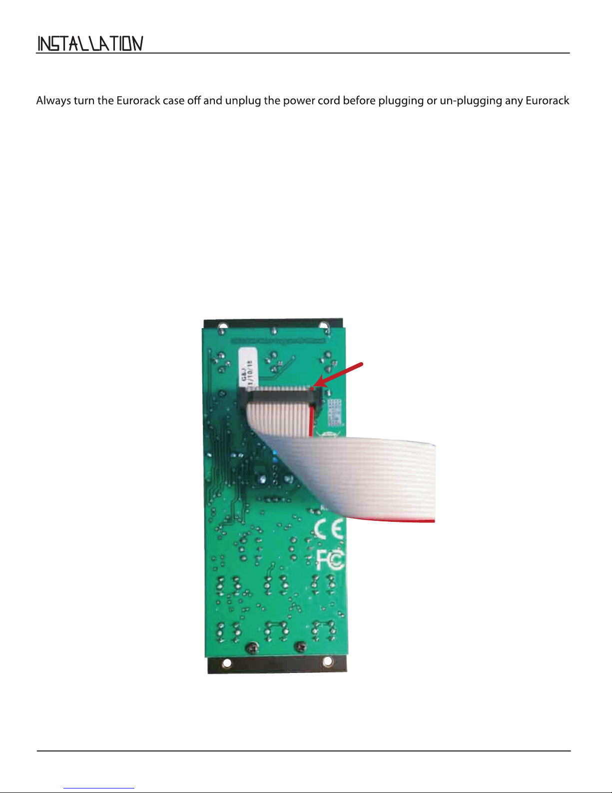
To install, nd 10HP in your Eurorack synthesizer case, conrm proper installation of inlcluded
eurorack bus board connector cable on backside of module (see picture below), plug the bus board
connector cable into the Eurorack style bus board, minding the polarity so that the RED stripe on the cable is
oriented to the NEGATIVE 12 Volt line on both the module and the bus board. On the Make Noise 6U or 3U
Busboard, the NEGATIVE 12 Volt line is indicated by the white stripe.
5
-12V
Please refer to your case manufacturers’ specications for location of the negative supply
Page 6
6
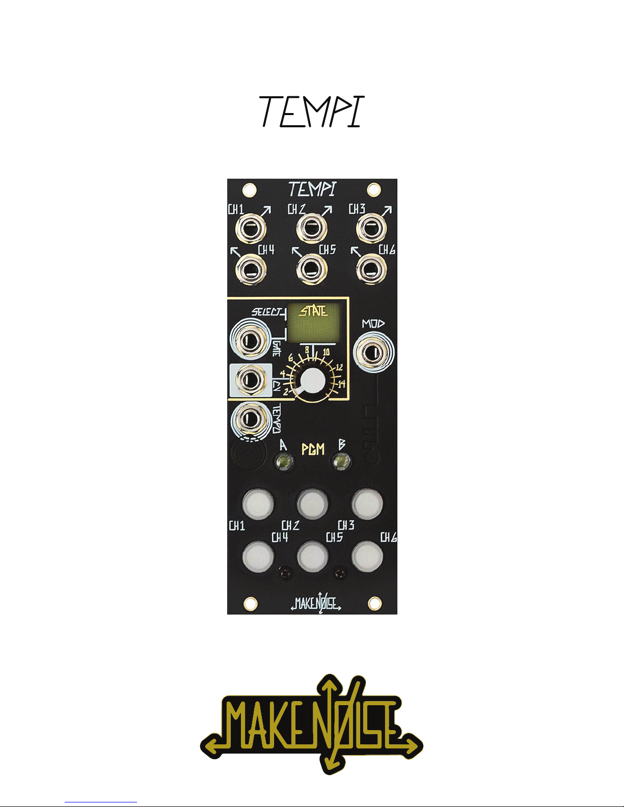
TEMPI is deep, but all you really need to know: patch a clock to the Leading Tempo Input and tap any Channel Button at a clock
rate of your choice. The Channel Button's LEDs ash to indicate the current clock rate, which changes in speed to match your taps.
A clock of that Tempo is available at each of the respective Channel Outputs. Adjusting the (6) tempi relative to one another will
create seemingly-innite rhythmic variations on the theme that is your patch. Much joy may be had without any further
knowledge, but I am certain you will want to know more, so read on.
TEMPI is a (6) Channel, polyphonic, time-shifting module. It provides an intuitive method for the creation and recalling of complex
clocking arrangements within a modular synthesizer system.
User Interface:
The primary User Interface and Programming elements for the module are (6) large, illuminated buttons (Channel Button 1-6) and
(2) smaller illuminated buttons: PGM_A and PGM_B. The module is able to store up to (64) clock/timing scenarios called States,
arranged in (4) Banks of (16) States. A center Bank LED is used to indicate the current Bank by color. Changes in States are
indicated by the Channel Buttons’ ashing LEDs.
There are Inputs for External Leading Tempo, a Gate Input for Mod, State Select via a CV Input (with Combo Pot for attenuation)
and/or Select Gate Input. The primary goal of this module is to have the maximum amount of artist-controlled musical variation
with a minimum amount of data input.
Firmware:
This manual is for TEMPI Firmware version tempi31. TEMPI modules running tempi31 will have an LED sequence on power up
where 1, 2, 3, 4, and 5 ash. TEMPI’s with serial numbers 1544 and above ship with tempi31 preloaded.
Download the latest rmware from: http://www.makenoisemusic.com/modules/tempi.
PRoGRaMMInG
IS sIMPLE!!
There are two methods of Programming TEMPI's Channels: HUMAN and MACHINE.
HUMAN Programming is simple:
[Tap] the Channel Button(s) at the rate you would like the associated Channel Output(s) to move.
MACHINE Programming is simple:
[Hold] PGM_A for DIVISIONS (÷) or PGM_B for MULTIPLES (*) and [tap] the associated Channel Button the number of times
corresponding to the desired DIVISION (÷) or MULTIPLE (*).
To MACHINE Program Channel-3 to “÷4“ (divide by four): [HOLD] PGM_A + [TAP] Channel Button-3 (4) times.
To MACHINE Program Channel-4 to “*6” (multiply by six): [HOLD] PGM_B + [TAP] Channel Button-4 (6) times.
Once a Channel is Programmed, whether by HUMAN or MACHINE, it may be ne-tuned by [holding] the associated
Channel Button and tapping PGM_A to slow down the clock incrementally or PGM_B to speed it up incrementally.
Programming:
For example:
Note: All (6) Channels are synchronized according to the associated Channel settings and Leading Tempo.
Hint: feel free to skip ahead to Tips and Tricks on Page 28.
Page 7
PAN EL ConTRoLS
7
9
11
15
1
4
5
7
8
10
12
14
17
2
3
6
20
21
22
13
16
19
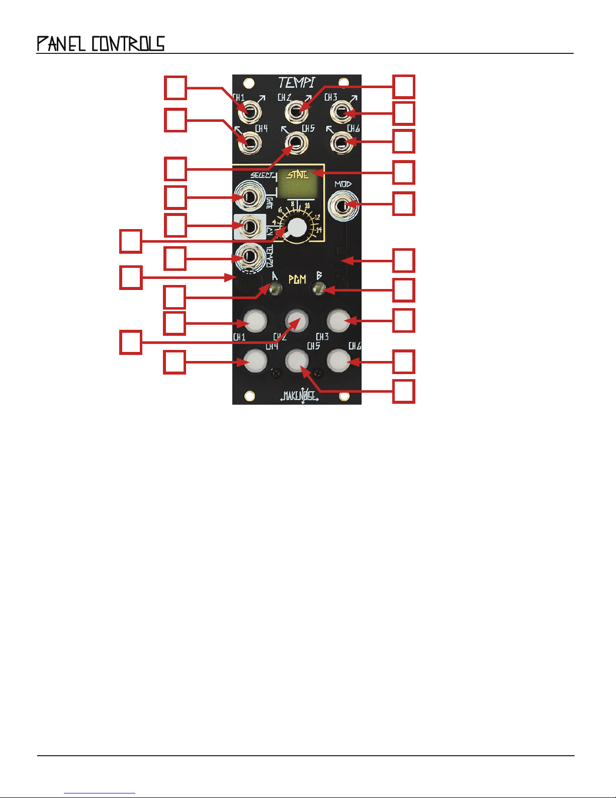
TEMPI Panel Controls
1. Channel 1 Output
2. Channel 2 Output
3. Channel 3 Output
4. Channel 4 Output
5. Channel 5 Output
6. Channel 6 Output
7. State Select Gate Input
8. State Select CV Input
9. Select CV Attenuator/Combo Pot
18
13. PGM_B Button/ LED
14. Channel Button-1 / LED
15. Channel Button-2 / LED
16. Channel Button-3 / LED
17. Channel Button-4 / LED
18. Channel Button-5 / LED
19. Channel Button-6 / LED
20. State LED
21. Mod Gate Input
10. External Leading Tempo Input
11. Tempo LED
12. PGM_A Button / LED
22. Mod LED
Page 8

8
When you rst power up a new TEMPI, Bank A will be lled with (16) States representing a selection of classic and new Clock
Divider/Multiplier settings. All these settings are user-editable and can be overwritten at will. Here's a short description:
STATE 1 All (6) CHannels are “÷1.” This setting is also the "Init" for all States in the other (3) Banks.
STATES 2-7 are Clock Divider States:
2. Powers of 2: ÷1, ÷2, ÷4, ÷8, ÷16, ÷32
3. Primes: ÷2, ÷3, ÷5, ÷7, ÷11, ÷13
4. Integers: ÷1, ÷2, ÷3, ÷4, ÷5, ÷6
5. Evens: ÷2, ÷4, ÷6, ÷8, ÷10, ÷12
6. Odds: ÷3, ÷5, ÷7, ÷9, ÷11, ÷13
7. Fibonacci: ÷2, ÷3, ÷5, ÷8, ÷13, ÷21
STATES 8-13 are Clock Multiplier States:
8. Powers of 2: *1, *2, *4, *8, *16, *32
9. Primes: *2, *3, *5, *7, *11, *13
10. Integers: *1, *2, *3, *4, *5, *6
11. Evens: *2, *4, *6, *8, *10, *12
12. Odds: *3, *5, *7, *9, *11, *13
13. Fibonacci: *2, *3, *5, *8, *13, *21
14. Multiples and *2, *3, *4, ÷2, ÷3, ÷4
Divisions:
15. Phase Demonstration: All (6) Channels are set to the same Tempo, but with (6) unique Phase values.
16. Non-Integer Division Demonstration: Each successive channel is one Fine Decrement slower than the previous, resulting in adjacent
Channels going slowly in and out of Phase with each other.
The Factory Settings of the Program Edit Page are as follows:
- Human Resolution 50%
- Shift = CW
- Run/Stop = OFF
- Shift = Jumbled
To Restore all Factory Settings, power o the system, hold PGM_B and Button-4 simulateously while powering back on.
Page 9
QUICK REFERENCE:
9
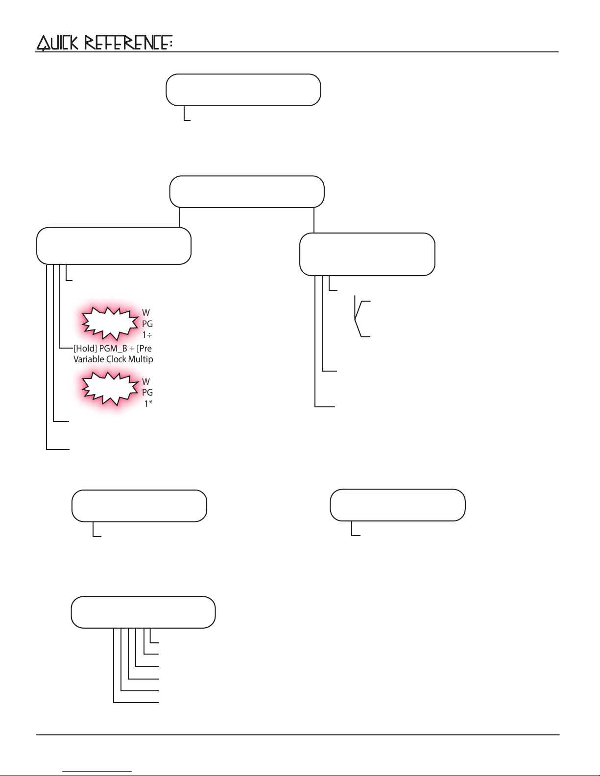
Human Programming
[Tap] Button1-6
Human Programming of Multiple and
Divisions of Leading Tempo
If enabled on Clock Edit Page, Tap Button1 to set Leading Tempo
Machine Programming
Variable Clock
Multiplier / Divisor
[Hold] PGM_A + [Press] Channel Button1-6 n times
for Variable Clock Divisor Coarse adjustment (1÷n)
While still holding PGM_A, [Press]
New to v.31
PGM_B y times for secondary divisor
1÷(n2 )
[Hold] PGM_B + [Press] Channel Button1-6 n times for
Variable Clock Multiplier Coarse adjustment (1*n)
While still holding PGM_B, [Press]
New to v.31
PGM_A y times for secondary multiplier
1*(n2 )
[Hold] Channel Button1-6 + [Press] PGM_A
for Variable Clock Fine Decrement
[HOLD] Channel Button1-6 + [Press] PGM_B
for Variable Clock Fine Increment
y
y
Phase Adjustment
[Press] PGM_A + PGM_B = On
[Hold] CHannel BUTTON1-6:
+ [Press] PGM_A n times to Phase Fine
Decrement Multiplier/Divisor value
+ [Press] PGM_B n times to Phase Fine
Increment Multiplier/Divisor value
[Hold] PGM_A + [Tap] Channel Button1-6 to Phase
Coarse Decrement Multiplier/Divisor
[Hold] PGM_B + [Tap] Channel Button1-6 to Phase
Coarse Increment Multiplier/Divisor
Mute
[Press] PGM_A = On
[Press] Channel Button1-6 to Mute Channels;
Muted Channels = Red
State Edit
[HOLD] PGM_A + PGM_B
[Press] BUTTON-1 to Recall current State
[Press] BUTTON-2 to Store current State
[Press] BUTTON-3 to Recall current Bank
[Press] BUTTON-4 to Copy selected State
[Press] BUTTON-5 to Paste over selected State
[Press] BUTTON-6 to Mutate over selected State
Mod Enable
[Press] PGM_B = ON
[Press] Channel Button-1-6
Mod Enabled Channels = Purple
Page 10
( CONT'D )
10
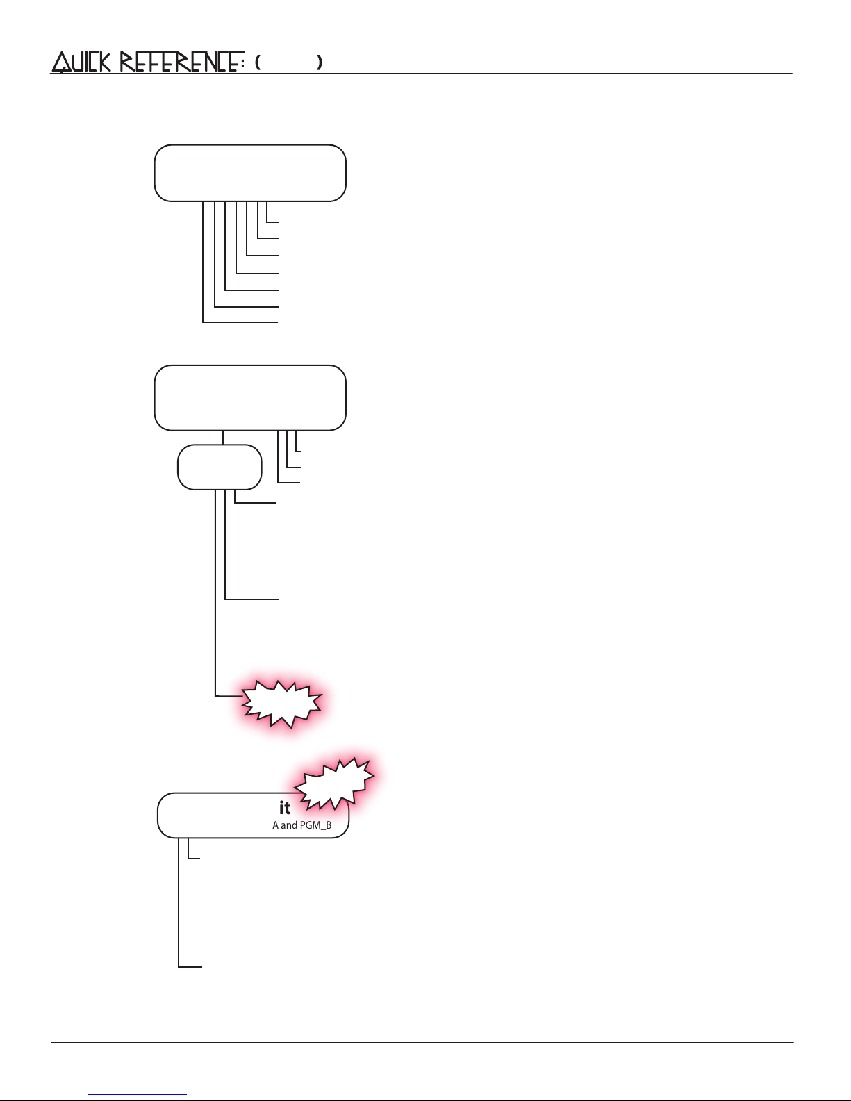
Bank Edit
[Press 2x] PGM_A = Flashing
Program Edit
[Press 2x] PGM_B = Flashing
Mod
Settings
[Press] Button-1 to Select Bank
[Press] Button-2 to Store All Banks and current Leading Tempo
[Press] Button-3 to Follow the Select and Tempo Busses
[Press] Button-4 to Copy selected Bank
[Press] Button-5 to Paste over selected Bank
[Press] Button-6 to Mutate over selected Bank
[Press] PGM_A to Exit Bank Edit
[Press] Button-1 for Human Resolution 100%
[Press] Button-2 for Human Resolution 50%
[Press] Button-3 for Human Resolution 25%
[Press] Button-4 for Shift:
CW
CCW
=
=
=
Red
Blue
Purple
Random
[Press] Button-5 for Run/Stop:
[Press] Button-6 for Jumbled Shift:
New to v.31
Unjumbled Shift = O
Run/Stop
Run/Stop All
Alt Run
New to v.31
= Red
= Blue
= Purple
Clock Edit
[Double-Press] PGM_A and PGM_B
[Press] Channel Button-1 Clock Width and Tap Tempo Settings:
Leading Tap Tempo/50% duty cycle, Clock = Purple
Leading Tap Tempo/10ms duty cycle, Trigger = Red
Leading Tap Tempo O/50% duty cycle, Clock = Blue
Leading Tap Tempo O/10ms Trigger = O
[Press] Channel Button-2-6 for Clock Width:
50% duty cycle Clock Output = Blue
10ms duty cycle Trigger Output = O
Page 11
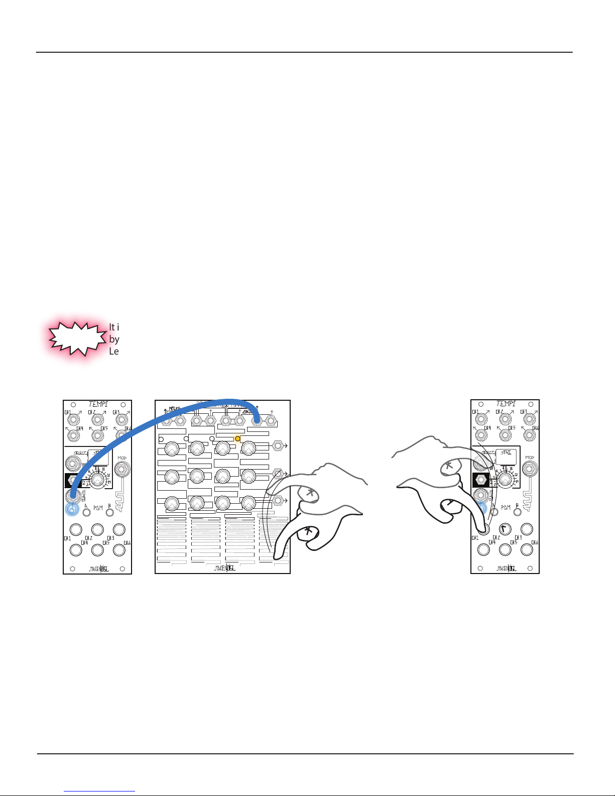
Leading Tempo
There are four ways to determine the Leading Tempo, which synchronize the (6) Variable Clock Outputs of the TEMPI:
Function, described on page 24).
2. When an External Clock is patched to the Leading Tempo Input, the External Clock source is followed after 2 pulses.
3. When an internally-connected bus line is used via the Tempo Bus, the generated Clock signal is Followed (refer to
Bank Edit Page’s Follow Setting, described on page 26).
4. New to v31 rmware: if Tap Tempo is enabled on the Clock Edit Page, tap Button-1 to set the Leading Tempo.
Note: While externally clocking, when changing Tempo from fast to slow, there will be some delay, as TEMPI needs a
minimum of 2 Clock pulses to measure the incoming Clock rate and lock into sync. If synchronizing TEMPI to a DAW
project, include 2 bars of silence, with sync clock running at the beginning of the composition so TEMPI locks into sync
when the composition starts. Also, for DAW Sync, try Run/Stop All (James Cigler mode) described on Page 20.
It is possible to tap the Leading Tempo by patching a Gate Output, for example, from the Pressure Points, to TEMPI’s Tempo
Input and tapping the desired Tempo on the Pressure Points. Remember: at least (2) taps are required. The TEMPI will lock on
to the new Tempo and Follow until a new Tempo is tapped. The Tempo is indicated by the Blue Tempo LED that ashes just
below the TEMPO Input jack.
It is also possible to use Channel 1 as the Leading Tap Tempo. To do this, rst migrate to the Clock Edit Page
by double pressing PGM_A and PGM_B. Then, press Channel Button-1 until it turns Purple to turn enable
Leading Tap Tempo. Once the Leading Tempo is set, you may program Variable Clocks again with Channel-1.
1. With nothing patched to the Leading Tempo Input, the last-Stored Tempo is used (refer to Bank Edit Page’s Store
New to v.31
11
To Program the Leading Tempo externally via tapping:
Programming with Leading Tap Tempo
(rmware v.31)
Variable Clock Programming:
The Variable Clock Outputs may be Machine Programmed by pressing and holding a combination of PGM_A or PGM_B and/or
Button(s)1-6 for the associated Channel Outputs. Each of the Variable Clock Outputs are Multiples or Divisions of the Leading
Tempo. When Variable Clock Outputs are Active (Mute Disabled) and/or Mod Disabled, the associated Channel Button LED(s) ash
Blue to indicate Clock High/Low.
NOTE: The default Pulse Width of the Variable Clock Outputs is 50% Duty Cycle. This can be changed to 10ms Triggers via
the Clock Edit Page, per rmware v.31.
Page 12
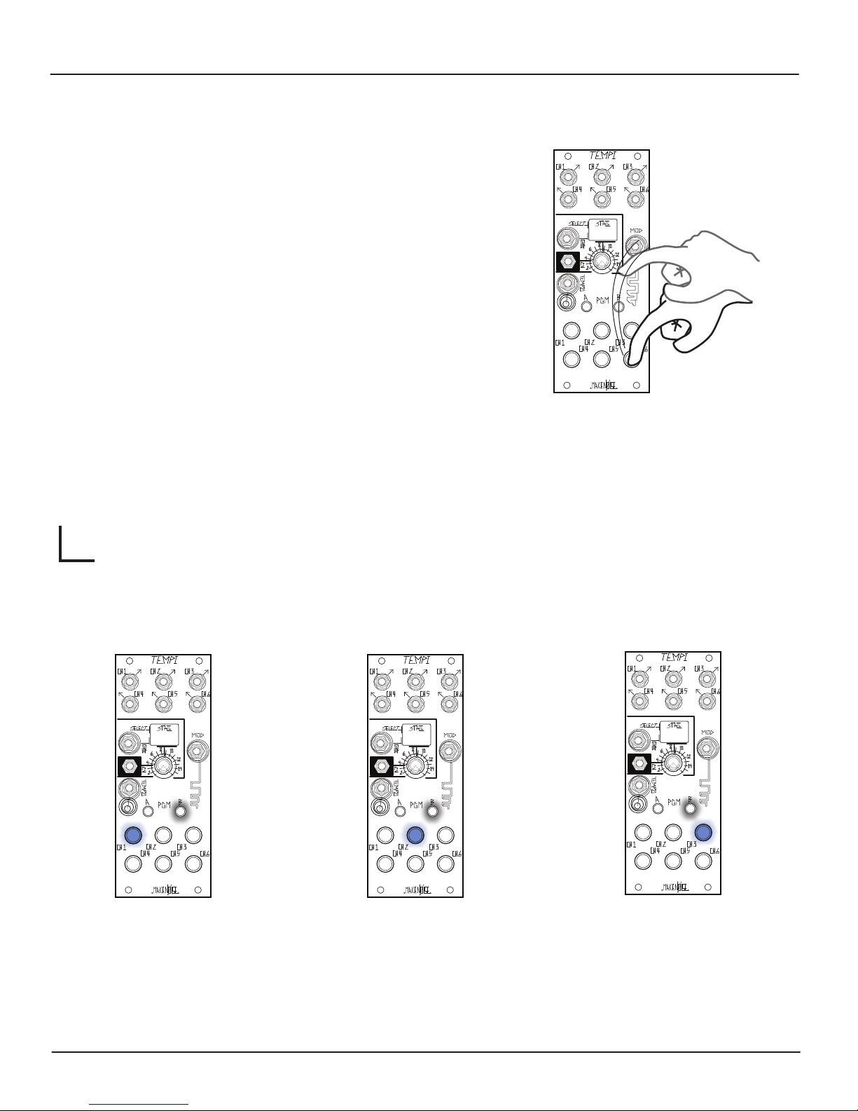
Programming Variable Clocks:
Human Programming
Human Clock Programming combines Multiplier/Divisor and Phase Settings
into one simple, tactile process.
For Human Programming, patch the Leading Tempo (i.e. MULT of the clock
patched to Tempo Input or any Channel set to 1:1 using Machine Multiplier or
Divisor) so that the timing is audible. Next, Program a Variable Clock by
tapping Buttons1-6 to aect the associated Channel Output(s) in order to
complement the Leading Tempo, resulting in either a Multiple or Division of
the Leading Tempo.
Notice, the User must tap each Channel Button at least twice in order to
Program a timing value. Changes happen as soon as algorithmically possible.
Previous values for a given Channel are overwritten as soon as a Channel
Button is tapped the second time.
While Human Programming, State changes are ignored. It is also possible to
Program several Channels at once. This makes it more intuitive to create
interesting timing arrangements.
IMPORTANT: these changes are not saved until you Store the State. Without
running the Store function (Page 24), changes are not held when the power is
cycled. This makes it easy to improvise with alternate versions of a Stored
theme.
12
For HUMAN Programming:
[TAP] Associated
BUTTON(s)1-6
RESOLUTION
Human Programming has three levels of Resolution determined by the Program Edit Page (to access, Press PGM_B twice).
The Resolution of Human Programming determines how the Variable Clocks are related to the Leading Tempo’s Phase
and Multiplier/Divisor. The Resolution setting is then indicated by which Channel Button1-3 LED is lit:
Human Resolution 100%
Results in the strictest relationships. This
is the same as Machine Programming
Coarse Multipler/Divisor and Phase
adjustments (see "Machine" section).
Human Resolution 50%
The Default setting, allowing for
something less strict than 100%,
but easier to use than 25%.
Human Resolution 25%
Establishes in the most free
relationships and in theory is the
equivalent as Machine Programming
Fine Multiplier/Divisor and Phase
adjustments.
Page 13
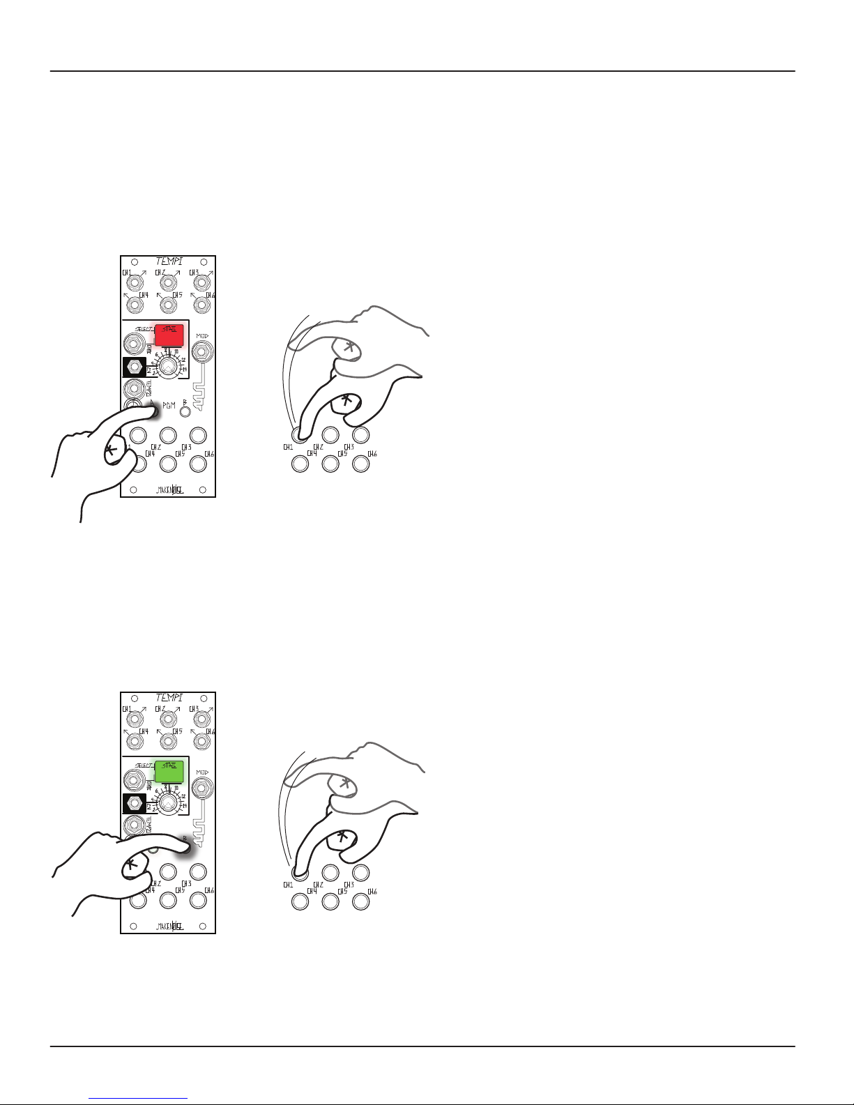
Machine Programming
There are two types of MACHINE Programming: Variable Clock Multiplier/Divisor and Phase.
13
Variable Clock Multiplier/Divisor Programming requires a combination of pressing and holding buttons in order to adjust
the associated Variable Clock Outputs:
For Variable Clock Divisor Coarse adjustment:
The user holds PGM_A and taps the desired
Channel Button (1-32) times in order to Program the
associated Variable Clock Output. It is possible to tap
Channel Buttons1-6 simultaneously in order to
Program several Channels at once. The TEMPI counts
the taps and sets this number as the Divisor value for
each Channel. If (32) taps are exceeded, the count
stays at maximum number of (32) and the counting of
subsequent taps is stopped. Changes take place as
soon as PGM_A is released.
The State LED lights red to indicate a Variable Clock
Divisor Coarse adjustment. Previous values for a given
Channel are overwritten as soon as the associated
Button1-6 is pressed while holding PGM_A.
Note: To return to a 1:1 relationship with Leading
Tempo (Default), hold PGM_A or PGM_B and press
the associated CHannel Button1-6 once.
[HOLD] PGM_A
+
[TAP] Associated
CHannel Button(s)
1-32 times
For Variable Clock Multiplier Coarse adjustment :
The user holds PGM_B and taps the desired
Channel Buttons (1-32) times in order to Program the
associated Variable Clock Outputs. It is possible to
[TAP] BUTTON(s)1-6 simultaneously, in order to
Program several CHannels at once. The TEMPI counts
the number of and sets this as the Multiplier value. If
(32) taps are exceeded, the count stays at maximum
number of (32) and the counting of subsequent taps
is stopped. Changes are made once PGM_B is
released.
+
[HOLD] PGM_B
[TAP] Associated
Channel Button(s)
1-32 times
The State LED lights green to indicate a Variable Clock
Multiplier Coarse adjustment. Previous values for a
given Channel are overwritten as soon as the
associated Button(s)1-6 is pressed while holding
PGM_B.
To return to a 1:1 relationship with the Leading
Tempo (Default), hold PGM_A or PGM_B and press
the associated Channel Button1-6 once.
Page 14
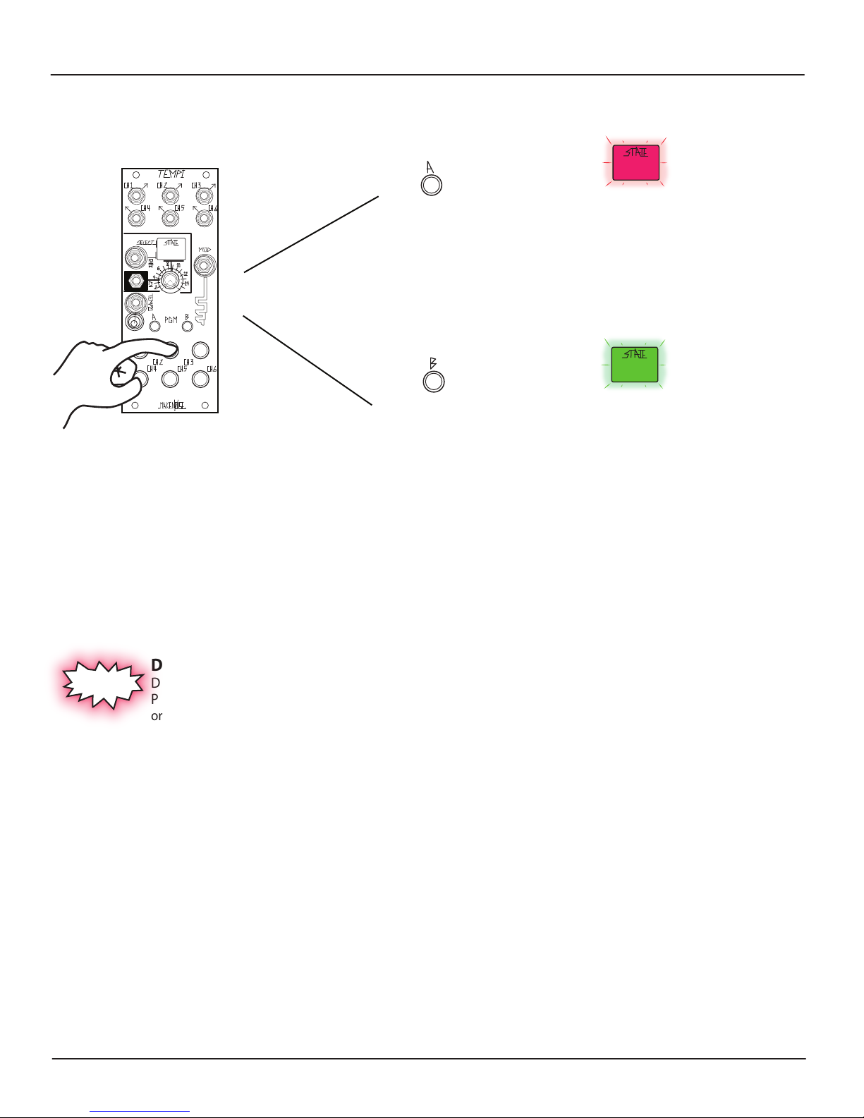
Machine Programming Multiplier/Divisor: (cont’d)
For Variable Clock Multiplier / Divisor
Fine adjustment:
14
[PRESS] PGM_A for
Variable Clock
Fine decrement
+
[PRESS] PGM_B for
[HOLD] Associated
BUTTON(s)1-6
You may Fine increment or decrement across the entire possible Variable Clock range, but you may nd it is much easier to
make a Coarse adjustment and then make a few Fine adjustments to nd unique timings.
Variable Clock
Fine increment
or
For Variable Clock Fine decrement (i.e. to make
slower), hold the associated Channel
Button1-6 and press PGM_A. The State LED
ashes Red to indicate a Variable Clock Fine
decrement has been made.
For Variable Clock Fine increment (i.e. to make
faster), hold the associated Channel
Button1-6 and press PGM_B. The State LED
ashes green to indicate a Variable Clock Fine
increment has been made.
Double Divisor / Multipliers
New to v.31
During Coarse Machine Programming, while holding down the associated PGM button, press the opposing
PGM button to double the divisor or multiplier. This makes it easy to quickly Program a Channel to
or Divisor Value of 32 without having to tap 32 times.
For example, hold PGM_A and press Button-2 twice for ÷2. Next, while still holding PGM_A, press PGM_B once for ÷4, twice for
÷
8, three times for ÷16, or four time for ÷32.
a Multiplier
Page 15
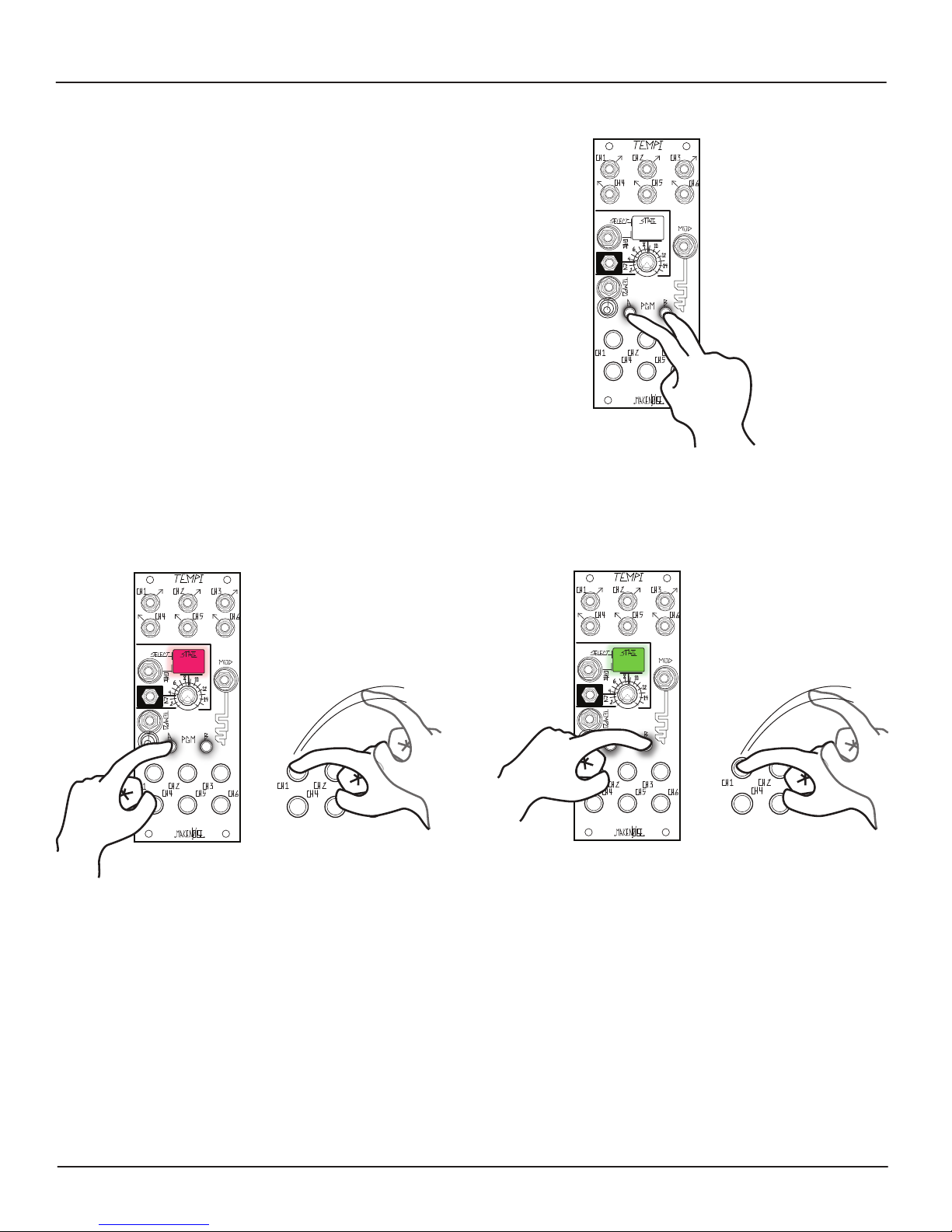
Machine Programming : Phase
15
The other way to Machine Program is by making Phase
adjustments. To enter the Phase Programming Page, press
PGM_A and PGM_B at the same time. While in the Phase
Page, both PGM_LEDs are on. State changes and Human
Programming are ignored. To exit, press both PGM_A and
PGM_B.
Next, Phase adjustments are performed in a similar way to
the Multiplier/Divisor settings using Coarse and Fine Phase
increments and decrements.
Once in the Phase Programming Page:
For Coarse Phase decrement:
[Hold] PGM_A
To begin Phase Programming,
[press] PGM_A and PGM_B
For Coarse Phase increment:
[Hold] PGM_B
[TAP] Associated
Buttons)1-6
one to four times
+
Hold PGM_A and tap the associated Channel Button(s) 1-4
times in order to Coarse Phase Program its Output(s). Coarse
Phase adjustments oset the Phase of the Channel's Output
by one cycle of the Leading Tempo. The State LED lights red
to indicate a Coarse Phase decrement has been made.
When programming Multiples of the Leading Tempo, Coarse Phase adjustments can be very subtle. Here is why: if the Channel is
set to an integral Multiple (e.g. * 4), Coarse Phase will have no audible eect, because the Channel's Clocks are output at the same times at
each pulse of the Tempo. If the Channel is set to a non-integer Multiple (e.g. * 4.25), the Channel's clocks will drift in and out of Phase with
the Leading Tempo over a period of several pulses of the Tempo. Coarse Phase of a Multiple in this situation only aects the zero-center
of this Phase-shifting: a subtle eect.
Hold PGM_B and tap a Channel Button(s), (1-4) times in order
to Program the associated Channel Output(s). Coarse Phase
adjustments oset the Phase of the Channel's Output by one
cycle of the Leading Tempo. The State LED lights green to
indicate a Coarse Phase increment has been made.
[TAP] Associated
Button(s)1-6
one to four times
+
Page 16
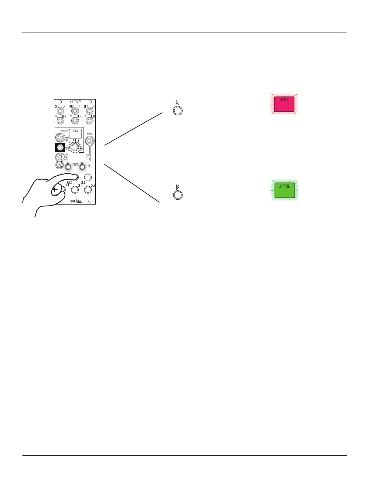
Machine Programming: Phase (cont’d)
16
While still on the Phase Programming Page:
For Fine Phase adjustment:
[HOLD]
Buttons(s)1-6
[press] PGM_A to
Fine Phase decrement
(i.e. lead ahead of Leading TEMPO)
+
[press] PGM_B to
Fine Phase increment
(i.e. lag behind Leading Tempo)
or
For Fine Phase decrement, hold the
associated Channel Button(s)1-6 and
press PGM_A. The State LED
ashes red to indicate a Fine Phase
decrement has been made.
For Fine Phase increment, hold the
associated Channel Button(s)1-6 and
press PGM_B. The State LED
ashes green to indicate a Fine Phase
increment has been made.
For Channels Programmed to be Divisions, Fine Phase adjustments oset the Phase of a Channel’s Output
by one quarter of a cycle of the Leading Tempo. Likewise, for Channels Programmed to be Multiples, it
osets the Phase of the Leading Tempo.
Coarse Phase adjustments override Fine Phase adjustments. In this way, Coarse Phase adjustments return to
integral divisors and multipliers, for instance, 1:1.
Page 17
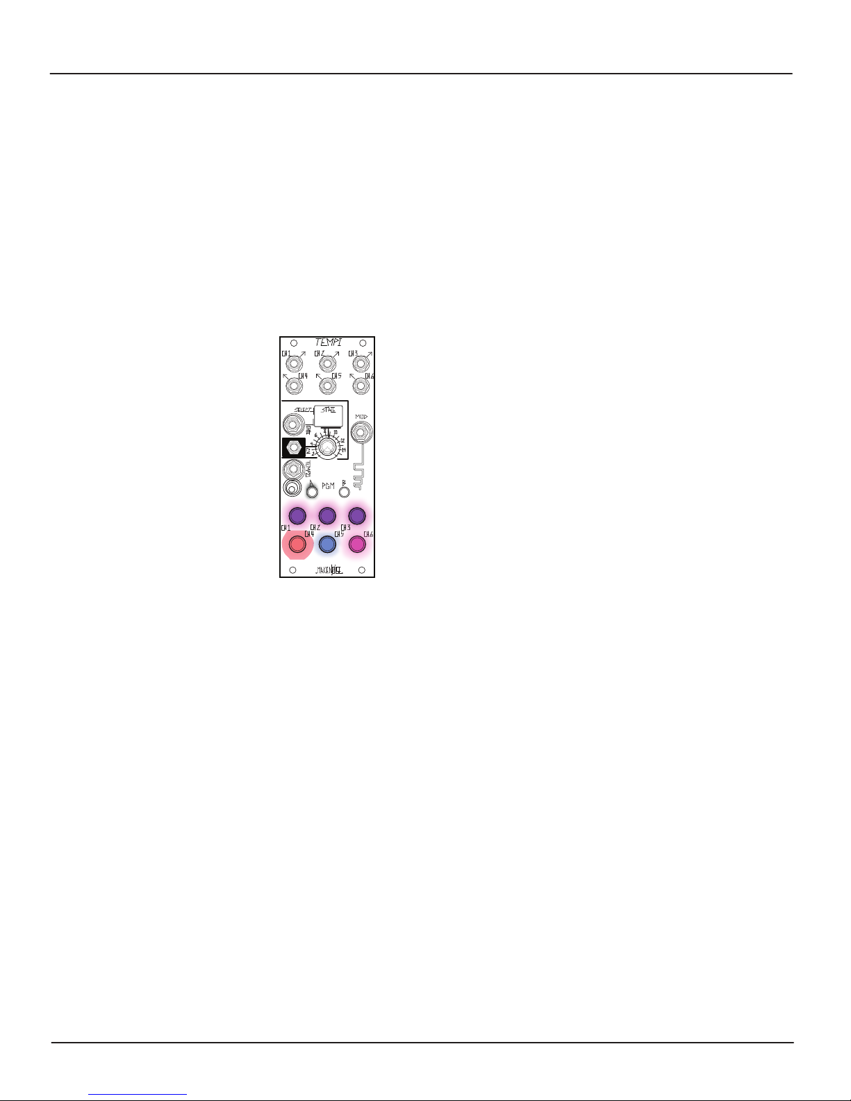
Mute
17
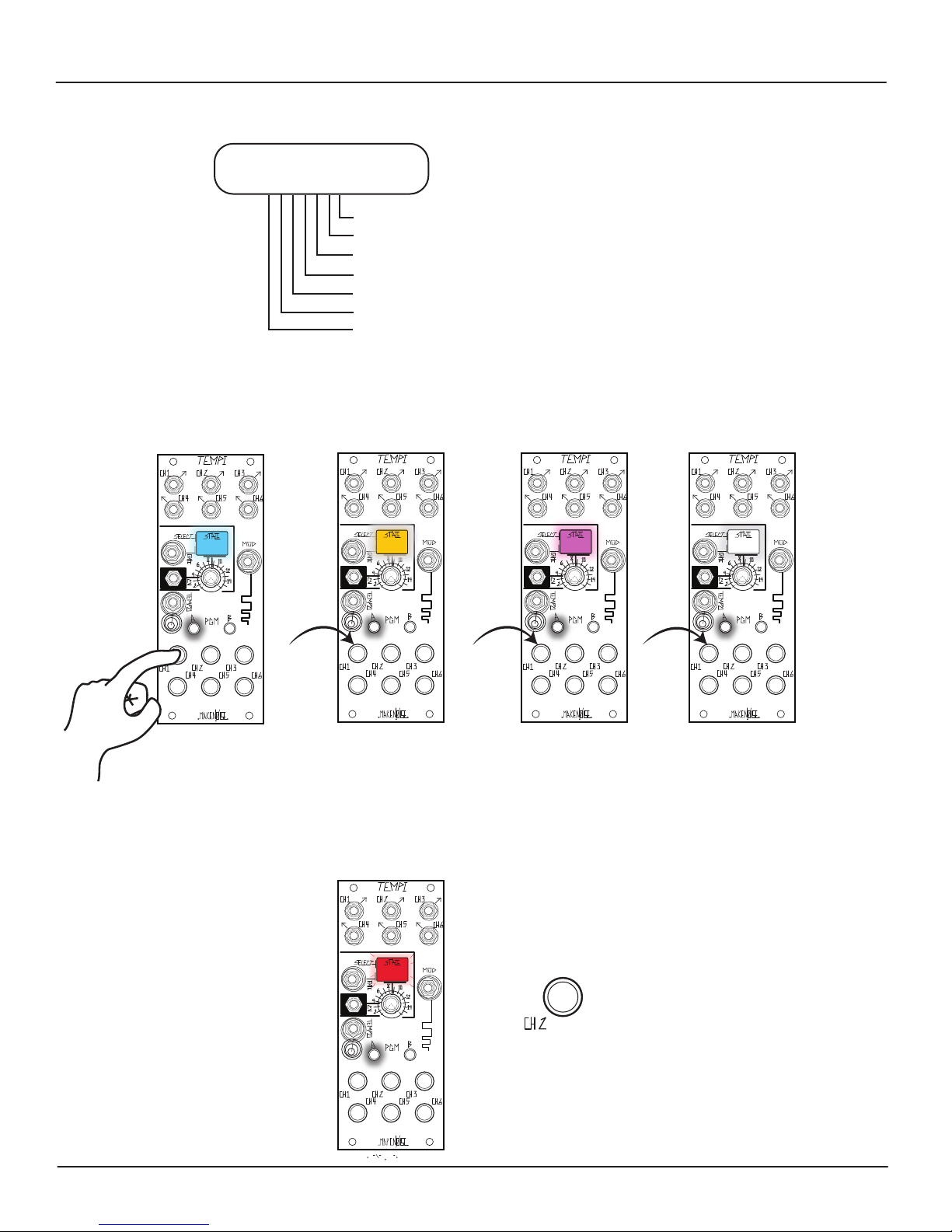
To Mute a Channel output, press PGM_A to toggle access the Mute Page. In order to exit the Mute Page, press PGM_A again. The
associated PGM_A LED lights to indicate that the Mute page is active. While active, State changes are ignored. To Mute a Channel, now
press its associated Channel Button to toggle its Variable Clock Output on/o. When Muted, the associated Channel Button LED is red and
ashes with each Rising Edge of each Clock to indicate the currently Programmed Variable Clock.
When a Channel is Active, its associated Channel Button is blue. If a Channel is Mod enabled while Active, the associated Channel Button
is purple. Alternatively, if a Channel is both Mod enabled and Muted, its associated Channel Button is pink (see below).
The purpose of Mute is to stop the Clock activity at the Channel Outputs while still allowing the user to Program desired changes. In this
way,
it is possible to Program a new Variable Clock into a Muted Channel. This is useful for cueing changes during live
performance by Machine or Human Programming. Exit the Mute page by pressing PGM_A.
Muted,
Mod disabled
Active,
Mod disabled
Active,
Mod enabled
Muted
and
Mod enabled
It is possible to Mute several Channels at once. This makes it more intuitive to create interesting timing arrangements.
Please note: these changes ARE NOT SAVED until you Store the State. Without running the Store State operation, changes are not
held when the power is cycled. This is useful for improvising with alternate versions of a Stored theme.
= RED
= BLUE
= PURPLE
= PINK
Page 18
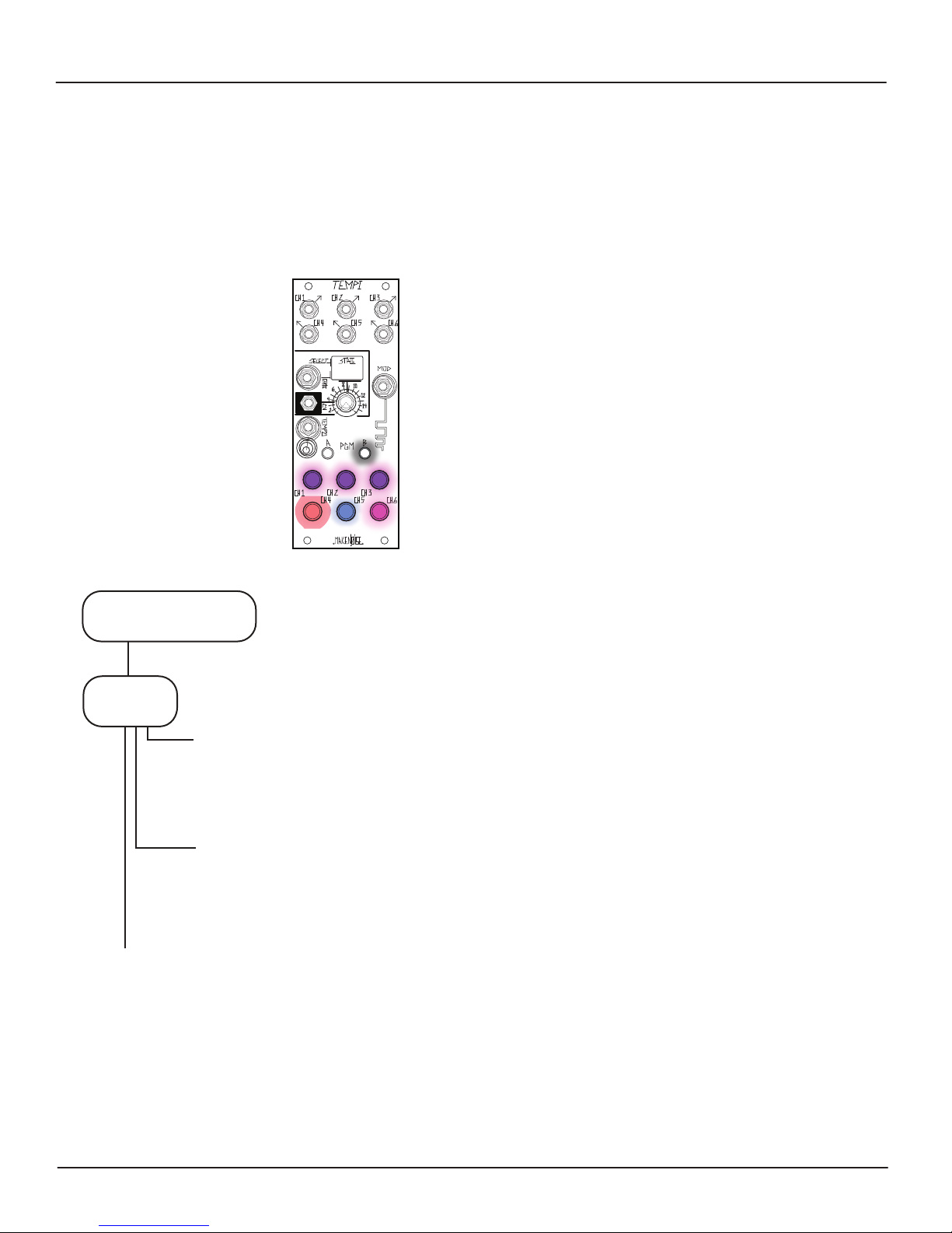
Mod Enable
18
The Mod function allows you to Program Shift or Run/Stop behavior. To Program the Mod function, press PGM_B to access the
Mod Page, indicated by the PGM_B LED. While on the Mod page, State changes are ignored. To Mod Enable a Channel, press its
associated Channel Button. Channels that are Active and Mod Enabled are purple. Channels that are both Mod Enabled and
Muted appear pink. If a Channel is Mod disabled, it is either Blue or Red. All Channels will continue to ash to indicate
currently-Programmed Variable Clock.
To exit the Mod Page, press PGM_B again.
MOD disabled,
= RED
Muted
MOD disabled,
= BLUE
Active
MOD enabled,
= PURPLE
Active
MOD enabled
= PINK
and
Muted
While Human or Machine Progamming, Mod remains disabled until
Progam Edit
[Double Press] PGM_B
Programming is completed. This behavior may be used creatively
in order to manually "freeze" the Mod functionality.
In order to easily create interesting timing arrangements, it is
MOD
SETTINGS
[Press] Button4 for Shift:
Red
Blue
Purple
Random
O
=
CW
=
CCW
=
=
O
(must have Run Stop Enabled)
[Press] Button5 for Run / Stop
Run/Stop
Run/Stop All
Alt Run
= Red
= Blue
= Purple
O
= O
(must have Shift Enabled)
possible to Mod Program several Channels at once. The Mod
function is determined by the Programming of the Mod Settings in
the Program Edit page.
The Mod Input aects the TEMPI according
to the Shift Behavior (causes timing information to move between
Mod-enabled Channels at each new Gate) and Run/Stop (causes
some or all Channels to Run, Stop, and/or Reset). The Mod LED
ashes Magenta to indicate a Mod function has been performed.
If both Shift and Run/Stop are enabled, then the State Select
Gate Input is used for Shift and the Mod Input for Run/Stop.
When only one behavior is enabled, the Mod Input is used for
the selected behavior.
[PRESS] Button-6 for Jumbled Shift:
Not Jumbled Shift = O
Jumbled Shift = Red
Please note: these changes ARE NOT SAVED until you Store the State. Without running the Store operation, changes
ARE NOT held when the power is cycled. This is useful for improvising with alternate versions of a Stored theme.
Page 19
Program Edit: Shift
19
The Shift Function trades the values for the Variable Clock Outputs and is accessed from the Program Edit page (Double Press
PGM_B).
For example, if Channels 2, 3, and 5 are set to be Shifted, the Variable Clock value at Channel 2 is swapped with the Variable Clock
value at Channel 5 at the Rising Edge of the Gate patched to the Mod Input, simultaneously replacing the value of Variable Clock 3
with that of the previous Variable Clock 2, allowing Channel 5 to take on the original value of Channel 3…. In other words, it
behaves as a Shift Register for the Variable Clock parameter values, where at each Shift command received, the values are passed
to the next active Mod Enabled Channel. These changes always occur at the Rising Edge of the signal patched to the Mod Input so
that when a Gate High is read, the Mod LED ashes Magenta and the Shift occurs immediately, allowing for an TEMPI Channel
patched to the Mod Input to control the Variable Clocks Shifts.
Types of Shift and Reset:
There are (2) Types of Shift behaviors, Programmed using Button-6 on the Program Edit Page:
• Not-Jumbled Shift is the Default and recalls the last stored settings when navigating away and back to State; Button-6 = OFF
• Jumbled Shift recalls to the values last utilized at that State when navigating away and back to a State; Button-6 = Red
Disengage Jumbled Shift when you want to easily return to a State’s Programmed Variable Clocks after Shifting Channels.
Note: Muted Channels are not Shifted. One could emulate a Shifted Mute by Programming a large Division and Shifting.
If both Shift and Run/Stop are both enabled (See Page 21), all State selection must be done using the State Select CV and
Combo Pot.
Tip: Shift is also useful for Programming variations of States where you want use the same Channels:
1. Create your initial State.
2. Copy and then Paste to another State.
3. Press PGM_B to enter the Mod Programming Page and set two Channels to be Shift Enabled, Purple.
4. Send a Gate signal to the Mod Input to swap their Variable Clock values.
5. Set these two Channels back to being Mod disabled.
Use this technique to trade Variable Clock values and create new States.
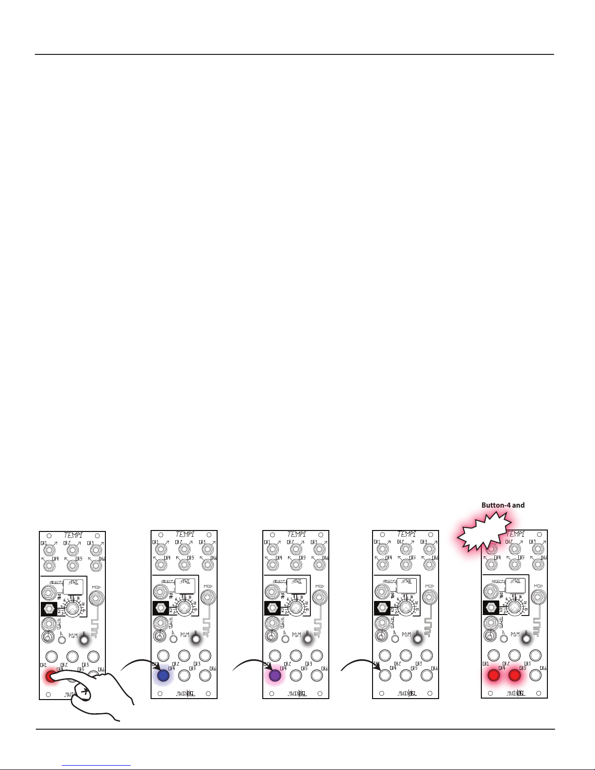
Using Button-4 on the Program Edit Page, Shift may be Programmed to operate in the following directions:
Clockwise, CW
Button-4 = Red
Counterclockwise, CCW
Button-4 = Blue
Random
Button-4 = Purple
(aka RODENT Mode)
Shift = O
Button-5 = O
Run/Stop and Shift
Button-4 and 5 = Red
New to v.31
Page 20
Program Edit: Run / Stop
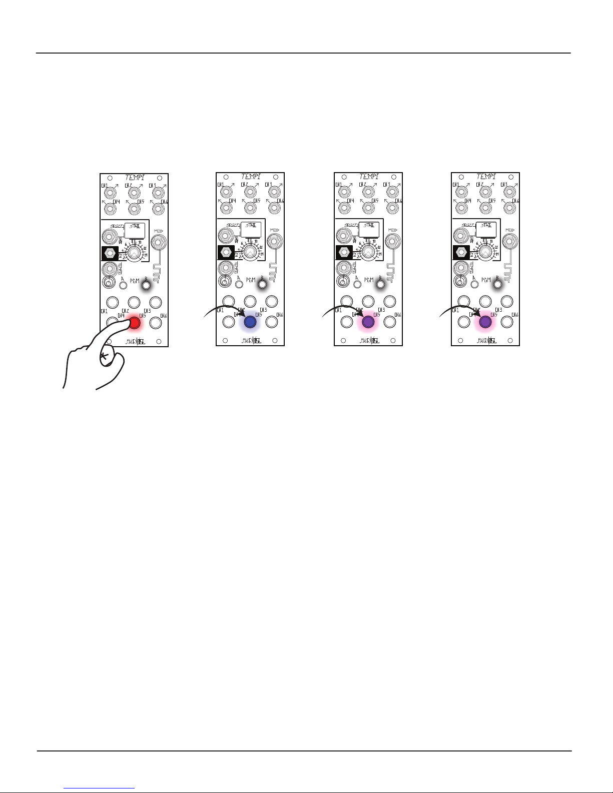
The Run/Stop Functions allows for modulating the phase relationship, resting, and re-setting the Variable Clock Outputs. When
set to Run, the Variable Clock Outputs operate as Programmed. When set to Stop, the Variable Clock Outputs are resting at 0V,
or O.
There are several types of Run/Stop behaviors to choose from that are Programmed using Button-5 in the Program Edit Page
(Double Press PGM_B):
20
Run/Stop
Button-5 = Red
Run/Stop
Run/Stop makes Mod Enabled Channels Run when a signal at the Mod Gate Input goes High and Stop when the Mod Gate Input signal
goes Low. The Mod LED is on when the Mod Gate is High and is o when it is Low. Run starts the channel immediately, regardless of
phase relationship to the Leading Tempo and preserves that Phase Oset until there is a State change or a Stop (ie. Mod Gate Low). This
allows for external modulation of a Channel's Phase relationaship to the Leading Tempo. Mod Disabled Channels are not aected. If a
signal patched to the Mod Input is an integer of the Leading Tempo (e.g. 1/1, 1/2, 1/4, 2/1...), Run/ Stop may also be used to Reset a
Channel.
Button-5 = Red
Run/Stop All
Button-5 = Blue
Alt Run/Stop
Button-5 = Purple
Run/Stop O
Button-5 = O
Run/Stop All
Makes all Channels Run on when a signal at the Mod Gate Input goes High and Stop when the Mod Gate Input signal goes Low, reseting
all CHannels on Run. The Mod LED is on when the Mod Gate signal is High and is o when it is Low. Mod Enabled Channels start
immediately regardless of phase relationship to the Leading Tempo, preserving that Phase Oset until there is State change or a Stop
(i.e. Mod Gate Low). Mod Disabled Channels start in Phase with the Leading Tempo. This behavior is nice for creating compositional
structures where you would like a Beginning or End. If synchronizing the TEMPI to DAW project, with the sync clock running, include 2
bars of silence at the beginning of composition so that TEMPI is locked into sync when it rst receives the Run signal at the Mod Input.
Run/ Stop All is also nice when used with a MIDI to CV module to convert MIDI Note On/Note O messages to Gate signals that may be
used to drive the TEMPI.
Alt Run/Stop
Alt Run/Stop makes Mod Enabled Channels Run when a signal at the Mod Gate Input goes High and Stop when the Mod Gate Input
signal goes Low. Mod Disabled Channels have the inverse behavior, Stopping when the Mod Gate Input is High and Running when the
Mod Gate Input is Low. The Mod LED is on when the Mod Gate signal is High and is o when it is Low. Channels start immediately,
regardless of their phase relationship to the Leading Tempo, preserving their Phase Oset until there is a State change or a Stop (i.e. Mod
Gate Low). This allows for external modulation of a Channel's Phase relationaship to the Leading Tempo. If a signal patched to Mod
Input is an integer of the Leading Tempo (e.g. 1/1, 1/2, 1/4, 2/1...), it may also be used to Reset a Channel while maintaining Phase with
Leading Tempo.
(a.k.a. James Cigler Mode) Button-5 = Blue
(a.k.a. Robert A.A. Lowe Mode) Button-5 = Purple
Page 21
Progam Edit: Run/Stop (cont’d)
21
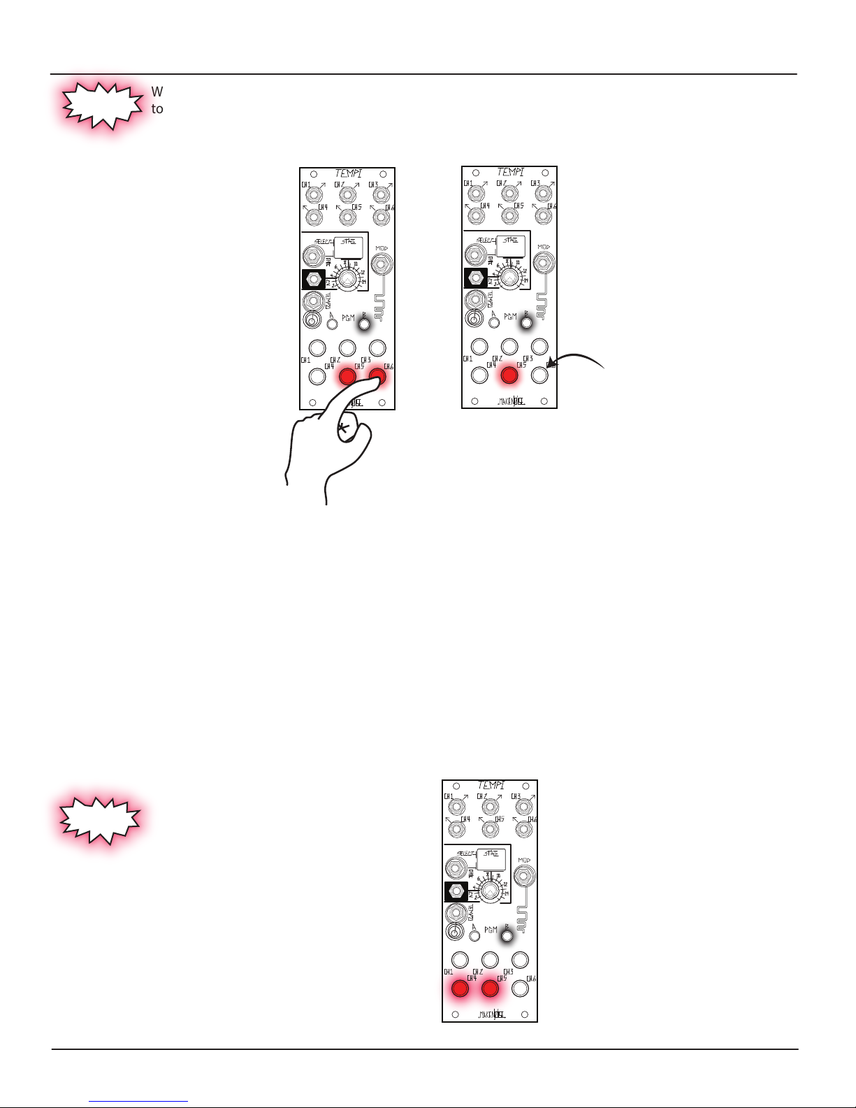
While on the Program Edit Page, Button-6 sets the behavior of the Mod Input jack for Shift and Reset behaviors
New to v.31
to be Jumbled or Unjumbled.
Jumbled
Button-6 = Red
Unjumbled
Button-6 = O
Jumbled Button-6 = Red
Any Phase O set changes created by Run/Stop messages will be preserved when navigating away from and back to a given
State. Phase O set changes are not saved upon power cycle.
Unjumbled Button-6 = O
Any Phase O set changes created by Run/Stop messages will NOT be preserved when navigating away from and back to a given
State.
Run/Stop and Shift
Button-4 and 5 = Red
Run/Stop and Shift
New to v.31
On the Program Edit Page, Run/Stop and
Shift can both be enabled at once.
The State Select Gate Input is used to Shift Variable Clock
Values (see page 19) while the Mod Input is used for
Programming Run/Stop behavior (see page 20).
Note: If both Shift and Run/Stop are both enabled, all
State selection must be done using the State Select CV
and Combo Pot.
Page 22
State Edit : States
TEMPI stores up to (64) timing scenarios referred to as States arranged into (4) Banks of (16). The State LED indicates Bank by color
and a change in State by ashing.
State is selected by either State Select CV or Select Gate, with State Select CV having top priority. The State Select Gate increments
the State value at the Rising edge of each Gate. In other words, when a State change is read at State Select CV, that change is
absolute and takes priority over State Select Gate changes.
There is a Gate Input for State Select Gate and a Combo Pot/CV Input for State Select CV. With nothing patched to State Select CV
Input, the State Select CV Combo Pot operates as a Panel Control which manually selects the State. The State Select CV Range is
0V to 5V.
To Reset to State 1, patch a Gate to the State Select CV Input and set the Combo Pot/attenuator so at Gate High, TEMPI goes to the
last State you would like to use (e.g. State 8). Next, patch a Clock or Gate to the State Select Gate Input and step through States 1
through 8. Send a Reset Gate with a short duty cycle to the State Select CV Input and at Gate Low, you will return to State 1. In
this way, it is possible to sequence any number of States linearly from State 1 to State n before Resetting.
Note: while on the Mute, Mod, Human, Machine, or Phase Programming Pages, State does not reect State Select changes via
CV or Gate until the active Programming Page is exited or completed. This behavior may be used creatively in order to manually
"freeze" the Mod functionality or State Select modulation. Also, if both Shift and Run/Stop are both enabled, all State selection
must be done using the State Select CV and Combo Pot, as the State Select Gate is used to Shift values.
22
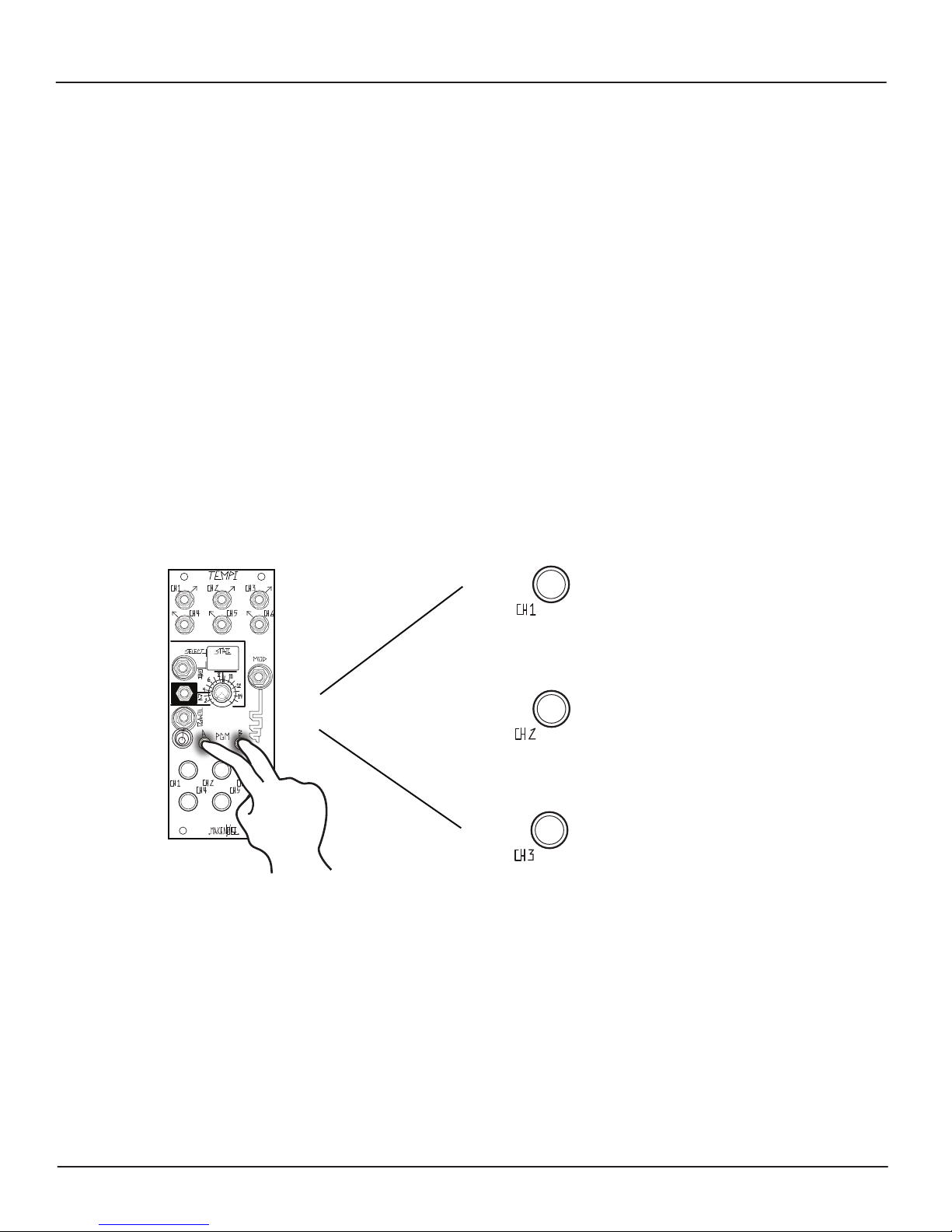
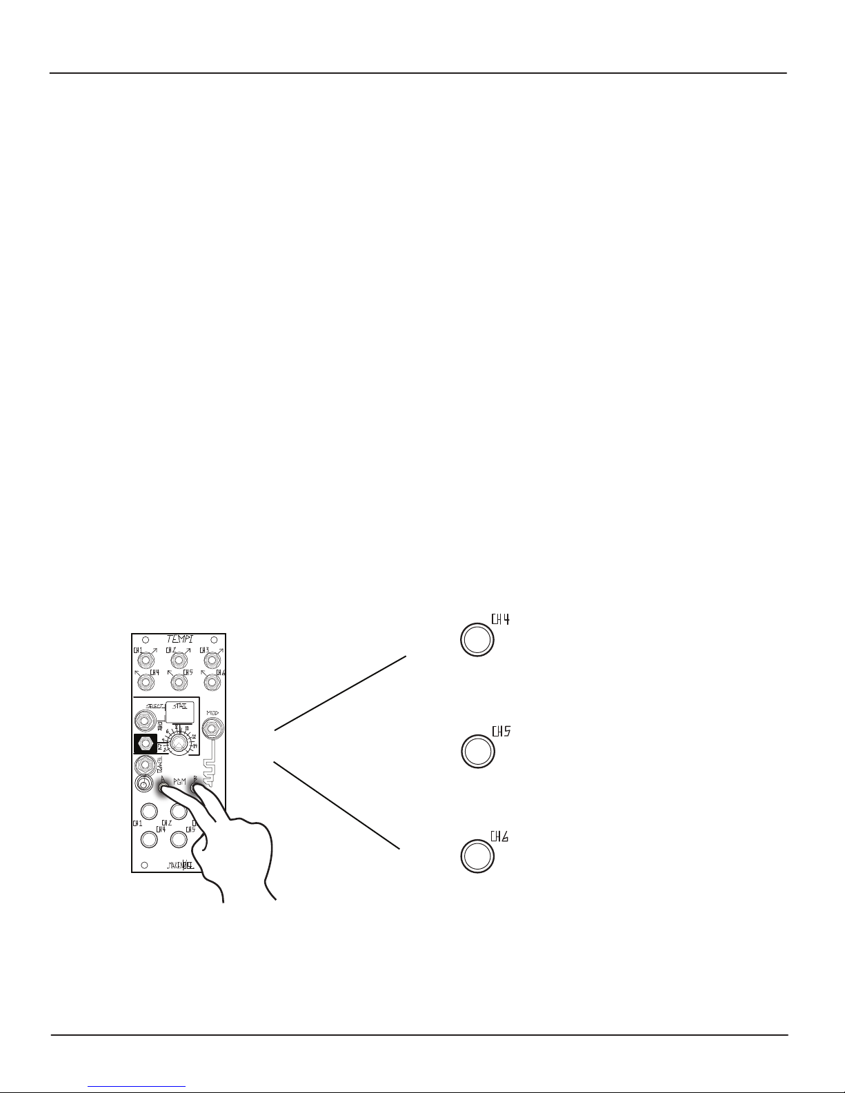
[Hold] PGM_A + PGM_B
To Store or Recall a State
+
Note: State Edit settings are saved on State Store.
[Press] Button-1
to Recall current State
or
[Press] Button-2
to Store current State
or
[Press] Button-3
to Recall current Bank from Memory
Page 23
State Edit: Copy, Paste, and Mutate State
In order to audition and select a State to Copy, rst use the State Select Panel Control to accurately choose the desired State. Note:
you may have to remove any modulation source patched to the Select CV Input. When you nd the desired State, hold both
PGM_A + PGM_B and press Button-4 to Copy. After a State is Copied, you may then decide to Paste an exact duplicate or a
Mutated version of the Copied State.
Once Copied, use the State Select Panel Control to audition and select a State into which you would like to Paste. Keep in mind,
you will be overwriting what is Stored in the currently-Selected State! To nalize the Paste operation, hold PGM_A and PGM_B
and press Button-5.
Alternatively, once a State has been Copied, you may use the State Select Panel Control to select a State over which you would like
to paste a Mutated copy. Mutate is very similar to the Paste operation, so keep in mind, you will be overwriting what is Stored in
the currently-Selected State!
When you nd the desired State to overwrite, hold both PGM_A + PGM_B and press Button-6 in order to paste a Mutated version
of the previously-Copied State. Mutate works by deviating to a small degree from the values that are already Progranmed within a
Copied State. To create more dramatic and alarming Mutations, simply, repeat the Copy and Mutate procedures again… and
again. Note: is possible to Copy, Paste, and Mutate several times to quickly and easily Program States or Banks.
Please note that these changes ARE NOT saved until you Store the State or Bank. Without running the Store operation,
changes are not held after power is cycled. This is useful for improvising alternate versions of a Stored theme.
23
To Copy, Paste, or Mutate a State:
[Hold] PGM_A + PGM_B
[Press] Button-4
to Copy a State
or
+
[Press] Button-5
to Paste a previously-Copied State
or
[Press] Button-6
to Mutate a previously-Copied State
Page 24
Bank Edit Settings
In order to enter the Bank Edit Programming page, double press PGM_A. The PGM_A LED ashes in order to indicate Bank Edit.
To exit the Bank Edit Programming page, double press PGM_A again.
24
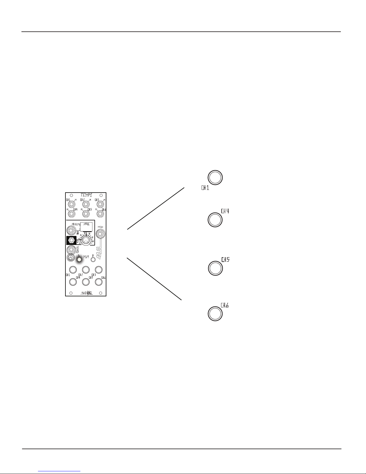
Bank Edit
[Double Press] PGM_A:
[Press] Button-1 to Select Bank
[Press] Button-2 to Store All Banks and current Leading Tempo
[Press] Button-3 to Follow Select & Tempo Busses
[Press] Button-4 to Copy selected Bank
[Press] Button-5 to Paste over selected Bank
[Press] Button-6 to Mutate over selected Bank
[Press] PGM_A to Exit Bank Edit
Select Bank:
While on the Bank Edit Programming page, press Button-1 in order to sequential Select Bank1, Bank2, Bank3, or Bank4.
The State LED color reects Bank change as follows:
Bank1 = Blue Bank2 = Amber Bank3 = Pink
Bank4 =White
(LED Colors May Vary)
Store All Banks:
While on the Bank Edit Page, to Store all contents of all Banks (i.e. All States and Leading Tempo), press Button-2. The State LED
ashes Red in order to indicate Store complete.
[Double Press] PGM_A
+
[Press] Button-2
to Store All Banks
Page 25
Bank Edit Settings (CONT’d)
25
COPY, PASTE, and MUTATE BANKS:
While on the Bank Edit Page, Press Button-1 to select the Bank to Copy. When you nd the desired Bank, press Button-4 to Copy.
In order to Paste, press Button1 to select the Bank into which you would like to Paste. Keep in mind: you will be overwriting what
is Stored in the selected Bank! Lastly, press Button-5 to complete the Paste operation.
Mutate works by deviating to a small degree from the values that are already Programmed within a Copied Bank. While on the
Bank Edit Page, press Button-1 to select the desired Bank to Mutate copy. In order to Mutate Paste, press Button-6 to paste a
Mutated copy. To create more dramatic and alarming mutations, simply repeat the Copy and Mutate procedures again… and
again.
Note: it is possible to Copy, Paste, and Mutate several times to quickly and easily Program a Bank.
Programmed with a 1:1 Multiple or Divisor Variable Clock value will have very little eect.
To Copy, Paste, or Mutate a Bank:
[Double Press] PGM_A
[Press] Button-1
to Select Bank
or
[Press] Button-4
to Copy selected Bank
+
or
[Press] Button-5
to Paste over selected Bank
Mutating a Channel that is
or
[Press] Button-6
to Mutate over selected Bank
Page 26
Bank Edit Settings (CONT’d)
26
Free / Follow
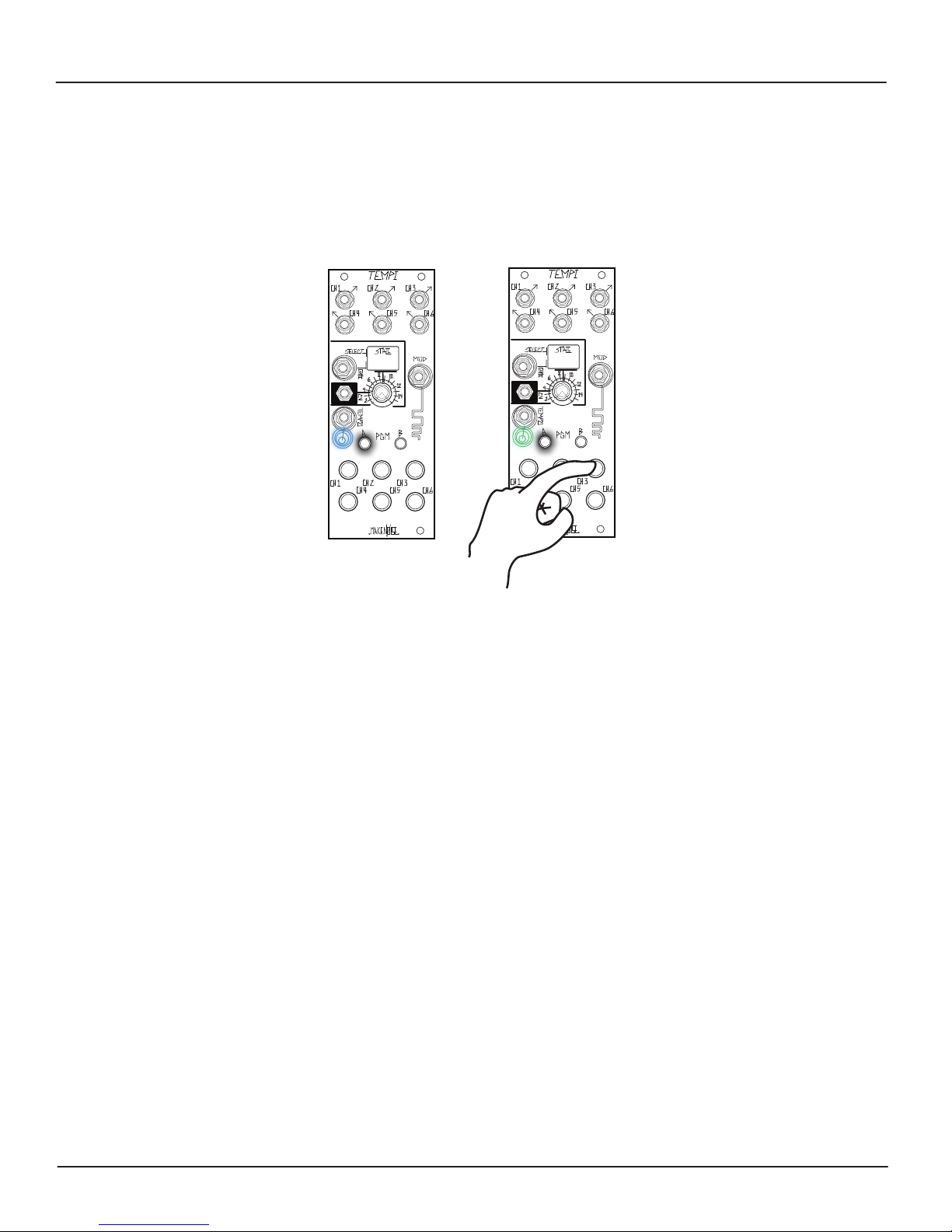
While on the Bank Edit Page, press Button-3 to set the TEMPI to Follow the Tempo and Select Busses. The TEMPO LED changes to
GREEN in order to indicate Follow. Press BUTTON-3 again to set TEMPI to be Free of the Tempo and Select Busses, indicated by the
Blue Tempo LED.
Free
Tempo LED = BLUE
Follow
Tempo LED = GREEN
While set to Follow, the TEMPI receives messages from the Select Bus that help determine the State and a Clock from the Tempo
Bus to determine the Leading Tempo. It does not transmit messages. The Panel Controls for State and Tempo are still useful
when the TEMPI is set to Follow. The State Select CV and Gate allow for osetting and modulating around the State that is
selected by the Select Bus. The Tempo Bus may be completely overridden by patching a Clock to the External Tempo Input, thus
allowing for an independent Leading Tempo.
Please note: changes ARE NOT saved until you go to the Bank Edit Page and press Button-2 to Store All Banks. Without
running the Store All Banks operation, changes are held only until the power is cycled. This is useful for improvising
alternate versions of a theme.
Page 27
Bank Edit: Select and Tempo Buses
27
The Select Bus and Tempo Bus utilize the often-inactive CV and GATE Busses in the Eurorack system in order to allow remote (i.e.
patch-less) control of State Selection and Tempo for TEMPI and other modules designed with this standard in mind. Any number
of TEMPI on the same Bus Board can be controlled simultaneously by these signals, simplifying the process of macro-control over
complex changes in a patch.
It is worth noting, TEMPI only recieves messages over the Select/Tempo Busses. It does not transmit. To engage Bus Control,
enter the Bank Edit page and press Button-3. When the Select and Tempo Busses are enabled, the Tempo LED will ash Green
instead of Blue. Now, the TEMPI will be controllable by Clock and State Select signals coming through these Busses.
Select and Tempo Busses Disabled
TEMPO LED = BLUE
Select and Tempo Busses Enabled
TEMPO LED = GREEN
Before engaging, make sure that no other modules are sending CV, Gate, or other signals (other than Select and Tempo signals)
through the Busses. More information regarding Select and Tempo Buses will become available as the standard is developed.
Clock Edit Page
New to v.31
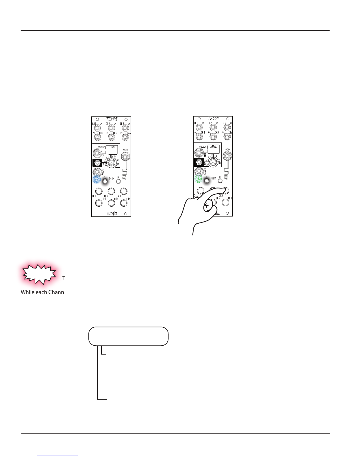
To Access Clock Edit Page by double-pressing PGM_A and PGM_B simultaneously.
While each Channel defaults to Clock Output with a 50% Duty Cycle, it may also be set as a 10ms Trigger. Additionally, Channel 1
can be used to set the Leading Tap Tempo. This replaces the Channel 1 Coarse Human Programming behavior until Leading Tap
Tempo is disabled again.
Clock Edit
[Double-Press] PGM_A and PGM_B
[Press] Channel Button-1 Clock Width and Tap Tempo Settings:
Leading Tap Tempo/50% duty cycle, Clock = Purple
Leading Tap Tempo/10ms, Trigger = Red
Leading Tap Tempo O/50% duty cycle, Clock = Blue
Leading Tap Tempo O/10ms Trigger = O
[Press] Channel Button-2-6 for Clock Width:
50% duty cycle Clock Output = Blue
10ms Trigger Output = O
Page 28

Tips and Tricks
28
• It is possible to Program several Channels at once. This makes it more intuitive to create interesting timing arrangements while
Machine, Human, Mod, Mute, and Phase Programming.
• Coarse Phase adjustments override Fine Phase adjustments. In this way, Coarse adjustments return to Integral Divisors and Multipliers,
for instance, 1:1 ratio.
• Mutes are not Shifted. One could emulated a Shifted Mute by programming a large Division and Shifting. For example, this allows for
turning o a voice within a patch or stopping a sequence.
• You must rst Copy a State or Bank before you can Mutate it.
• If Human Programming and you would like to use only Integer Divisions or Multiples, set Human Resolution to 100% ([PRESS] Button-3
while on Program Edit Page). This will ensure instantly perfect Programming of ‘four on the oor’ beats, or something similar.
• If using Shift, and changing States, turn Jumbled Shift On to preserve Shifted channels after leaving and returning States. This is useful
for creating Live modications to timing arrangements. This is also the default.
• If you would like to return Shifted channels to their original positions, turn Jumbled Shift O and then leave and return to State. This is
useful for creation Live modications to timing arrangements without messing up the original settings.
• The State Select CV and Panel Control override any State stepping that occurs. So if you stepped through States with State Select Gate
and then changed State Select Panel Control, it immediately takes it back to the Panel Control (or CV) setting. For example, if you
set to State 1 then State Step (6) times with State Select Gate to State 6 and then turn the State Select Panel Control to State 2,
the next State would be State 3, as the knob position and State Select CV takes priority.
• It is possible to Program a new Variable Clock into a Muted Channel. This is useful for cueing changes during live performance.
• The Shift function and Modded Channels do not activate without a Trigger or Gate patched to the Mod Gate Input. For
Shift, at least (2) Channels must be Mod Enabled. If only (1) Channel is Mod Enabled, it can only Shift with itself (i.e. no
audible eect).
• Mutating a Channel that is Programmed with a 1:1 Divisor or Multiple value will have very little eect.
• If a State or Bank is Copied and then Mutated, it is still possible to Paste an un-Mutated iteration of the associated State or Bank.
•To create more dramatic and alarming Mutations, simply repeat the Copy and Mutate procedures again… and again. In this way, it is
possible to Copy, Paste, and Mutate for easily Progranming a State or Bank.
• For a stable Tempo, once the Leading Tempo is learned, unpatch the Clock from the Leading Tempo Input. As such, to create Clock
Jitter, pre-process your External Clock before it is patched to the Leading Tempo Input. Even as the External Clock rate changes,
the TEMPI’s Variable Clock Outputs will remain synchronized with each other, as long as the External Clock remains patched to its
Leading Tempo Input.
•Self-patching the TEMPI's Outputs to the Mod, State Select Gate Input, and even State Select CV Input can be very useful. However, be
aware that self-patching to the Leading Tempo input will result in a feedback loop that causes the module to quickly reach
maximum or minimum Tempo value (unless the Channel patched to the Leading Tempo Input is set to 1:1, in which case it will
have no eect).
•To Reset to State 1, patch a Gate to the State Select CV Input and set the Combo Pot/attenuator so at Gate High, TEMPI goes to the last
State you would like to use (e.g. State 8). Next, patch a Clock or Gate to the State Select Gate Input and step through States 1
through 8. Send a Reset Gate to the State Select CV Input and at Gate Low, and return to State 1. In this way, it is possible to
sequence any number of States linearly from State 1 to State n before Resetting.
Page 29
Patch Ideas
29
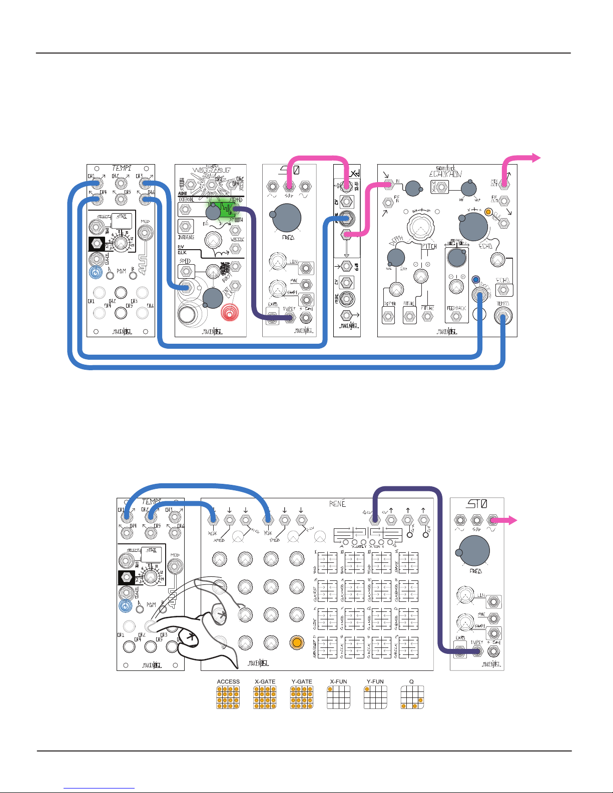
Stutterphon:
Patch external Master Clock to ECHOPHON’s Tempo Input. Set Echo Time to 12:00 or less for Multiple of Master Clock. Use TEMPI
to patch a division of the Master Clock to ECHOPHON’s Freeze Gate Input to create stutter eects synchronized to a multiple of
master clock. Experiment with Depth setting for subtle pitch-shifting of these stutters or deep harmonizing to add counter
melodies.
1:1
÷4
Using TEMPI to drive Rene:
Patch from two Channels of TEMPI’s output to Rene’s X-CLK and Y-CLK Inputs. Human Program one of the clocks to be a division
of the other. Observe the Rene’s Cartesian behavior. Optionally, try patching the remaining clocks from the TEMPI to the Rene’s
X-Mod and Y-Mod inputs and experiment with the various Gate Logic settings on the X-Fun and Y-Fun pages (see Rene Manual,
Appendix D ).
1:1
1:1
1:1
÷4
Page 30
Patch Ideas
30
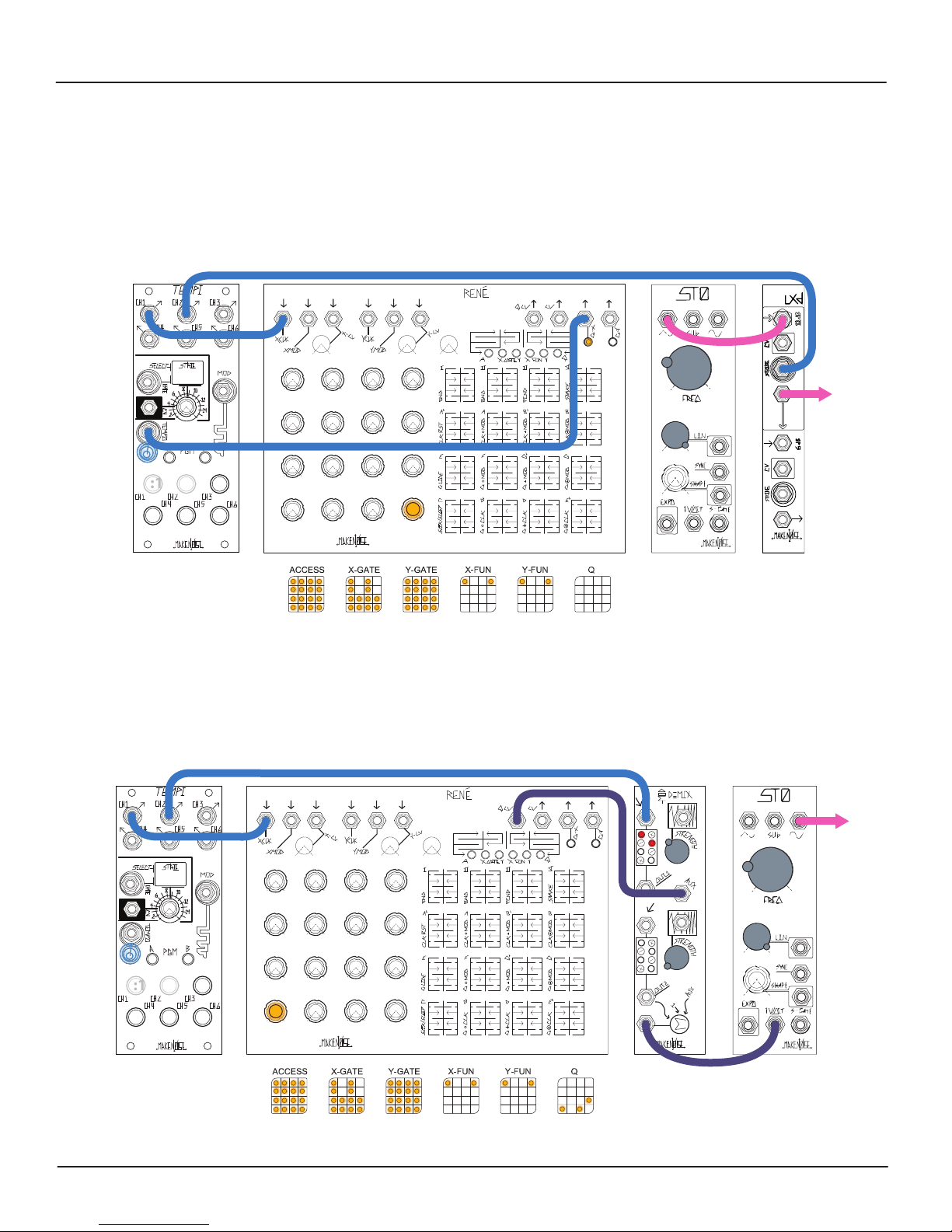
Clock Murmur:
Patch an Output of the Tempi to Rene’s X-CLK input to start the sequence. Make sure Snake Mode is engaged via the X-Fun Page.
Now, patch from Rene’s X-Gate Output back into TEMPI’s Tempo Input. Back on Rene, migrate to the X-Gate page and remove
every other gate on the top two rows, as illustrated in the chart below. This feedback loop causes the TEMPI to hickup slightly
every time the Gates driving the Leading Tempo change from half-time to 1:1 and back. (Recall: it takes two clock pulses in order
for TEMPI to program a new Leading Tempo). To best hear this eect, use one or more of the TEMPI’s Outputs to Strike a Low Pass
Gate like the Optomix or LxD.
1:1
1:1 1:1
TEMPI Transposition
Patch one of TEMPI’s Outputs programmed 1:1 with the Leading Tempo to Rene’s X-CLK input to start the sequence. Patch Rene’s Qcv
Output to the Signal Input on ModDemix Channel 1. Next, patch another TEMPI Output programmed to ÷16 to ModDemix’s Aux Input.
With Channel 2’s attenuverter full counter clockwise, patch from ModDemix’s SUM Output to the 1V/Oct input of an oscillator like the STO
in order to sequence it’s pitch. The Channel 1 attenuverter sets the degree of the transposition.
1:11:1 ÷16
 Loading...