

Page 1
v. 2.0
Page 2
This device complies with Part 15 of the FCC Rules. Operation is subject to the following two
conditions: (1) this device may not cause harmful interference, and (2) this device must accept
any interference received, including interference that may cause undesired operation.
Changes / modications not approved by the Make Noise Co. could void the user’s authority
to operate the equipment.
This equipment has been tested and found to comply with the limits for a Class A digital
device, pursuant to part 15 of the FCC Rules. These limits are designed to provide reasonable
protection against harmful interference when the equipment is operated in a commercial
environment. This equipment generates, uses, and can radiate radio frequency energy and, if
not installed and used in accordance with the instruction manual, may cause harmful
interference to radio communications.
makenoisemusic.com
Make Noise Co., 414 Haywood Road, Asheville, NC 28806
Page 3

Limited WARRANTY:
Make Noise warrants this product to be free of defects in materials or construction for a period of one year
from the date of purchase (proof of purchase/invoice required).
Malfunction resulting from wrong power supply voltages, backwards or reversed eurorack bus board cable
connection, abuse of the product or any other causes determined by Make Noise to be the fault of the user
are not covered by this warranty, and normal service rates will apply.
During the warranty period, any defective products will be repaired or replaced, at the option of Make Noise,
on a return-to-Make Noise basis with the customer paying the transit cost to Make Noise. Please contact
[email protected] for Return To Manufacturer Authorization.
Make Noise implies and accepts no responsibility for harm to person or apparatus caused through operation
of this product.
Please contact [email protected] with any questions, needs & comments, otherwise...
go MAKE NOISE!
http://www.makenoisemusic.com
THANK YOU:
DSP Wizard: Tom Erbe, Soundhack
Beta Analyst: James Cigler
Test Subjects: Surachai, Pete Speer, Aaron Abrams
Spiritual Advisor: Richard Devine
Special Thanx to the Springer Tempophon machine for inspiration
soundhack:http://www.soundhack.com
Page 4
Electrocution Hazard!
Always turn the Eurorack case o and unplug the power cord before plugging or un-plugging any Eurorack
bus board connection cable cable.
Do not touch any electrical terminals when attaching any Eurorack bus board cable.
The Make Noise Echophon is an electronic music module requiring 70mA of +12VDC and 40mA of -12VDC
regulated voltages and a properly formatted distribution receptacle to operate. It is designed to be used
within the Eurorack format modular synthesizer system.
Go to http://www.makenoisemusic.com/systems.shtml for examples of Eurorack Systems and Cases.
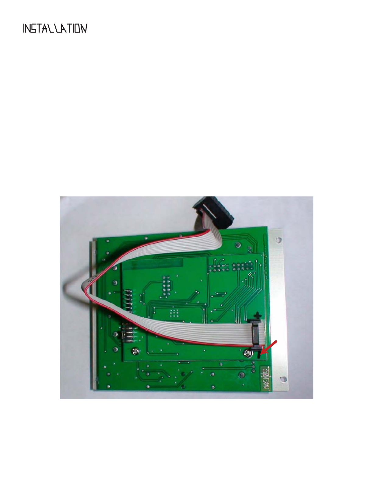
To install, nd necessary space in your Eurorack synthesizer case, conrm proper installation of included
eurorack bus board connector cable on backside of module (see picture below), plug the bus board
connector cable into the Eurorack style bus board, minding the polarity so that the RED stripe on the cable is
oriented to the NEGATIVE 12 Volt line on both the module and the bus board. On the Make Noise 6U or 3U
Busboard, the negative 12 Volt line is indicated by the white stripe.
-12V
Please refer to your case manufacturers’ specications for location of the negative
supply.
Page 5
1A
2A
3A
5A
6A
1B
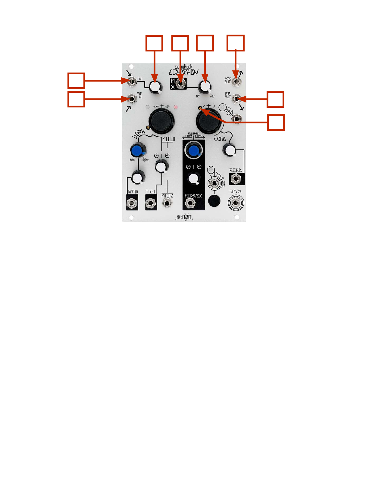
Echophon Panel Controls
Audio Input/ Output
1A. Signal IN: AC coupled, expects standard signal level of 10Vpp signal.
2B
4A
2A. Level Control for Signal IN: overloads at 70% to 100%
3A. Mix CV IN: unipolar control input. Range 0V to +5V.
4A. Trim for Mix Control (see calibration procedure)
5A. MIX Panel Control: blends between DRY (un-processed) signal & WET (processed) Signal. With nothing
patched to MIX CV IN, works as standard panel control. With Signal Patched to MIX CV IN, works as
attenuator for that signal.
6A. MIX OUT: 10Vpp (depending upon Level setting and source material), AC coupled.
External Feedback
1B. Feedback IN: AC coupled return for external FB loop. Expects standard signal level of 10Vpp.
2B. Feedback OUT: AC coupled, 10Vpp send for external FB loop.
Page 6
5C
1C
2C
3C
4C
6C
7C
9C
8C
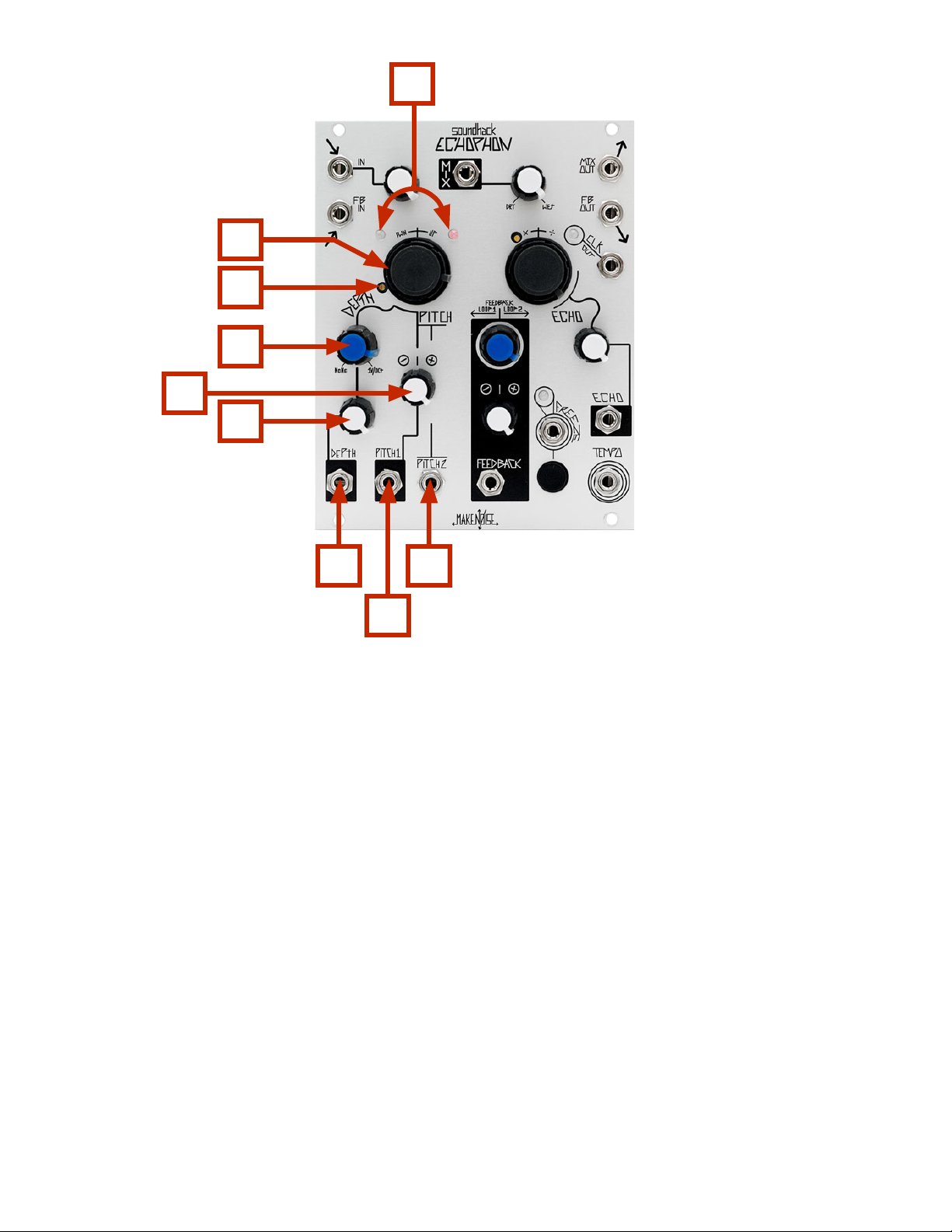
Echophon Panel Controls (cont’d)
Pitch Shift
1C. Temphonic LEDs: indicate mechanics of the pitch-shifting machine.
2C. Pitch Panel Control: bipolar panel control. At 50% no pitch shift, greater than 50% shifts pitch UP and
less than 50% shifts pitch DOWN. Range is ALWAYS dependent upon DEPTH setting.
3C. Pitch Trim (see calibration procedure)
4C. DEPTH Panel Control: unipolar panel control that sets the index of the pitch shift, ranging from
sub-microtonal chorusing to 4 octaves harmonizing.
5C. PITCH 1 CV Attenuator: bipolar attenuator for PITCH 1 CV IN.
6C. DEPTH CV Attenuator: unipolar attenuator for DEPTH CV IN.
7C. DEPTH CV IN: unipolar control signal input. Range 0V to +5V.
8C. PITCH 1 CV IN: bipolar control signal input. Range +/- 4V.
9C. PITCH 2 CV IN: bi-polar control signal input. Range +/- 2V for total of 4 octave range. Set Pitch Panel
Control to full CCW for uni-polar control such as analog sequencer, or to 50% for bi-polar control
signal such as CV Keyboard.
Page 7
3D
1D
2D
4D
3F
5D
6D
3E 1F
1E
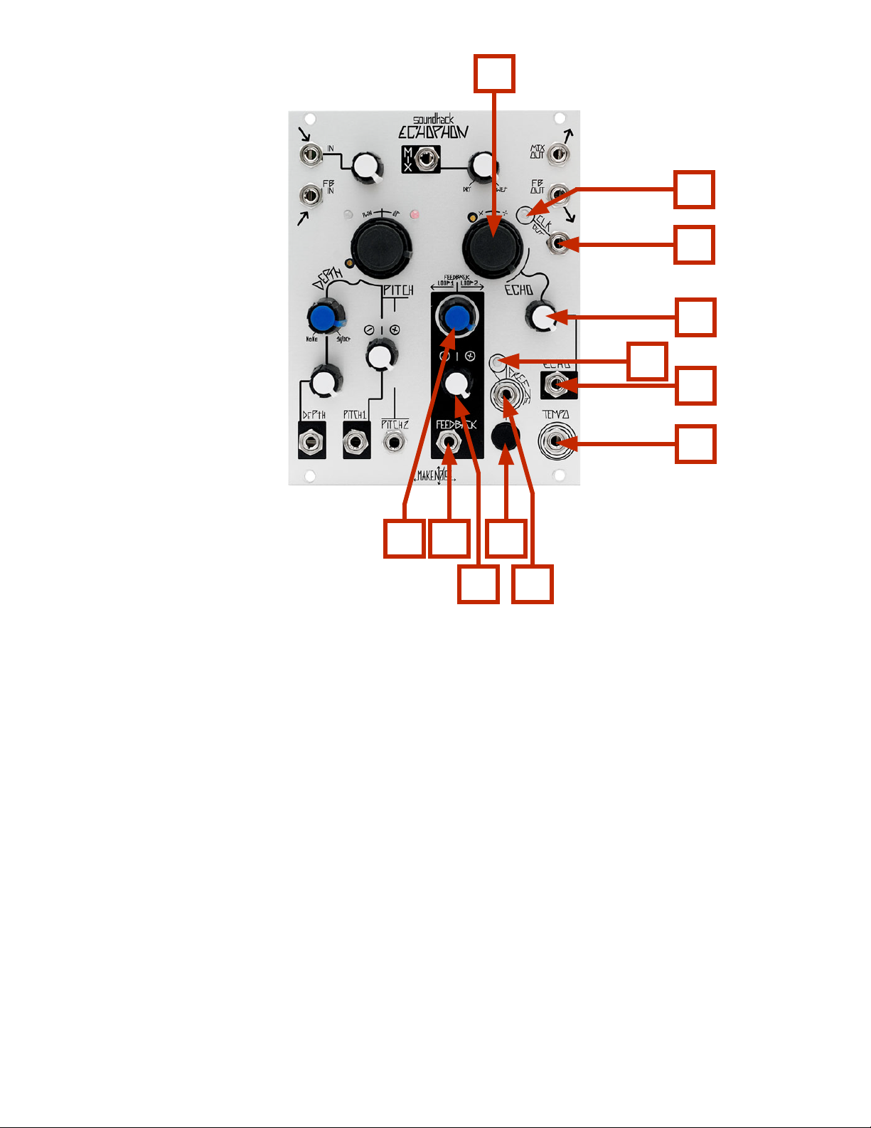
Echophon Panel Controls (cont’d)
2E
Echo
1D ECHO TIME LED: Indicates Tempo of the ECHO CLOCK
2D ECHO CLOCK OUT: outputs the ECHO TIME as 4ms wide clock pulse. 0V-5Vpp
3D ECHO TIME Panel Control: sets time/ length of Echo, from 7ms to 1.7 sec
4D ECHO TIME CV Attenuator: unipolar attenuator for Echo Time CV IN.
5D ECHO TIME CV IN: unipolar control signal input. Range 0V to +8V.
6D TEMPO IN: allows synchronization of Echoes to multiple or division of an external Clock. While following
external Tempo the Echo Time Controls will Multiply or Divide the incoming clock. Requires Clock/
Gate signal amplitude of at least 1.5V and width of at least 6ms.
Internal Feedback Loops
1E FEEDBACK CV IN: bipolar control signal input. +/- 8V.
2E FEEDBACK CV Attenuator: bi-polar attenuator for FEEDBACK CV IN.
3E FEEDBACK Panel Control: bipolar panel control that determines the amount and direction of feedback.
At 50% there is no feedback. Turning CCW from 49% to 0% sends increasing amounts of feedback to
the loop around the Pitch Shifter. Turning from 51% to 100% send increasing amounts of feedback to
the loop around the Echo.
2F
Freeze
1F FREEZE Button: toggles FREEZE on/ o. When FREEZE is ON, all sound in the ECHO chamber is held until
FREEZE is turned OFF.
2F FREEZE Gate IN: will FREEZE on Gate HIGH. 1.5V trigger signal to operate.
3F FREEZE LED: indicates status of the ECHO chamber. Lights when FREEZE is activated.
Page 8

Getting Started:
Patch the signal to be processed into the SIGNAL IN (1A). The associated Level Control (2A) accommodates
modular synthesizer signals of 10Vpp for the rst 70% of its rotation. Beyond 70% on the Level Control,
there will be clipping followed by digital overloading. Take your output from the MIX OUT (6A) and patch to
your nal mixer/ monitoring system. Set the MIX Panel Control (5A) to about 50% for the typical patch.
The DEPTH control (4C) acts to set the index or range of the PITCH Shifting. It could be thought of as a
Digital VCA for the control voltages patched to PITCH 1 (8C) and PITCH 2 (9C) as well as the PITCH Panel
Control (2C). At DEPTH 0% there is no Pitch Shifting. Up to around 50% the Pitch Shifting is subtle, introducing chorusing eects. Increasing the DEPTH beyond 50% will create increasingly deeper pitch shifting until
nally at 100% the full 4 octave range of harmonizing is possible. The DEPTH parameter is best modulated
with linear functions such as an envelope generated by the MATHS.
The PITCH controls alter the perceived pitch of the sound. PITCH 1 (8C) has an associated bi-polar attenuator (5C) allowing you to add or subtract the control signal patched from the setting of the PITCH Panel
Control (2C) and PITCH 2 (9C). PITCH 1 is perfect for patching an LFO for Vibrato eects. By adjusting the
associated attenuator (5C) the depth of the Vibrato is programmable. PITCH 2 (9C) is well suited for patching a sequencer CV or Keyboard CV. Since most analog sequencers generate uni-polar CV in the range of 0V
to 5V, you will need to set the PITCH Panel Control (2C) to Full CCW (0%) in order to control the entire range
of PITCH.
The ECHO Time panel control (3D) sets the length of the Delay line, ranging from 7ms at Full CCW to 1.7sec
at Full CW. Patch into ECHO CV IN (5D) and adjust the associated uni-polar attenuator (4D) to modulate
ECHO Time. Just about any source will work wonderfully as this parameter has a smooth exponential
response tailored for great modulations.
If you patch an external Clock signal to the TEMPO INput (6D), the ECHOPHON will follow that Clock, and the
ECHO Time controls act to set a Divisor or Multiplier of that Master Tempo. The slowest clock (input or
output) is limited to the delay time, so to get a 12/1 out, you need a fairly fast clock in (1.7s/12 or .15s).
The FEEDBACK Panel Control (3E) is bi-polar with 0 to 49% sending FEEDBACK through LOOP1, 50% sending
no feedback and 51% to 100% sending Feedback to LOOP 2. Loop 1 goes around the PITCH Shifter, and so
each regeneration will be pitch shifting again, resulting in spiraling echoes that rise out of audibility or fall
into sub sonic obscurity. LOOP 2 will create traditional ECHO Repeats. Bi-polar modulation of FEEDBACK is a
unique element of the ECHOPHON allowing the two feedback loops to be continuously cross-faded. When
FEEDBACK goes to ZERO (at 50%, 0V), the delay line empties out after one echo, so the ratio between ECHO
Time and the rate of the signal modulating FEEDBACK will be an important factor in bi-polar modulation. A
pronounced bi-polar modulation of FEEDBACK is achieved with a mid-range LFO (around 4hz). Audio Rate
bi-polar modulation is subtle and gorgeously resonant. Signals such as an ASR envelope with a long Fall
Time or a sequenced program change from Pressure Points are useful for animating a sound within a composition. For example, a cluster of notes is emphasized by increasing feedback resulting multiple repeats.
Using FREEZE:
Once your signal is passing through the ECHOPHON, pushing the FREEZE button (1F) or sending a Gate
HIGH to the FREEZE Gate IN (2F), will cause the ECHOPHON close the ECHO chamber and hold the sound
inside. The FREEZE LED (3F) will light to indicate this state. While the ECHOPHON is FREEZEd the PITCH may
be controlled using the PITCH parameters. The ECHO Time parameters will change the sound destructively.
Feedback controls will do nothing while the ECHOPHON is FREEZEd. Note is that the REEZE Button is Top
Priority, meaning that the FREEZE Gate in will have no eect when FREEZE has already been toggled ON
using the FREEZE Button.
Page 9

Using the External Feedback Loop:
Patch the FB OUT (2B) to an external module such as the modDemix. Set up the external module to process
the FB OUT signal. For the modDemix you could set up the typical Ring Modulation patch where you have a
sine or triangle waveform from a VCO patched to the CARRIER input on the modDemix. The FB OUT signal
would be patched to the Signal IN on the modDemix. Take modDemix Signal OUT and patch to the nal
stage in the external feedback loop, the VCA. The Optomix works nicely as the nal VCA stage in an external
feedback loop patch. Patch the Signal OUT from the modDemix to the Signal IN on the Optomix. Take the
Signal OUT from the Optomix to the FB IN (1B) on the ECHOPHON. Set the Optomix CONTROL Level to
determine the amount of regenerations.
Other modules could be placed in the loop to create more complex sounds, but it is important to have a
VCA (or manual attenuator) at the end of the loop for gain control. Without this nal gain control stage, the
external feedback loop might be hard to tame and utilize in a musical way.
CLOCK Division/ Multiple: While a Master Clock is patched to the TEMPO IN, the ECHO Time control acts to
multiply or divide the Master Clock. Below is a list of the possible ratios:
ECHO Time <50% 1/16, 3/32, 1/8, 3/16, 1/4. 3/8, 1/2, 3/4,
ECHO Time 50% = 1/1
ECHO Time >50% = 3/2. 2/1, 3/1, 4/1, 6/1, 8/1, 12/1
The slowest clock (input or output) is limited to the delay time, so to get a 12/1 out, you need a fairly fast
clock in (1.7s/12 or .15s).
TIP & TRICKS:
-The Signal IN is optimized for 10Vpp signals; however, it is possible to create much more powerful signals
within the euro system, so use the Level Control to achieve clean sounds.
-Patch a VCA or attenuator in front of the FB IN.
-Use FB IN for a secret sound that will occur only as an echo repeat.
-Use FB OUT to skip the pitch shifting machine.
-Modulate DEPTH to create Harmonic sequences.
-To achieve pitch-shifting, DEPTH must be set to greater than 10%
-Subtle PITCH Shifts (low DEPTH setting)
-To sequence full range of PITCH, set PITCH Panel Control to FULL CCW and patch sequencer CV to PITCH 2.
-When the delay time is below 20 milliseconds, the delay is acting like a comb lter. FEEDBACK will aect the
harmonics being emphasized.
-The slowest CLOCK OUT is limited to the delay time, so to get a 12/1 out, you need a fairly fast clock (1.7s/12
or .15s) patched to TEMPO IN.
Page 10

Patch Ideas:
All patches require signal to be processed patched to Signal IN with Level Control set to accommodate
incoming signal and MIX OUT patched to nal mixer/ monitoring system.
The Pillars of Hercules: this patch is designed for processing percussive sounds.
Mix 50%, DEPTH 75%, PITCH 0%, FEEDBACK 0% (for LOOP 1), ECHO Time 0%
Mult Envelope used for controlling Amplitude of the percussive sound to ECHOPHON DEPTH CV IN and set
associated attenuator to 50%
Sliding Universal Phonogene: create loops, transpose, maintain original tempo.
DEPTH to 0% (no pitch shift), MIX 100%, FEEDBACK 50% (no feedback)
Patch external Master Clock to TEMPO IN. Set ECHO Time to 50% or more for division of Master Clock. Utilize
FREEZE Button to grab a loop. Now set DEPTH to 100% and use PITCH to play FREEZEd sound melodically
without changing tempo.
Digicello:
Patch Pink Noise to Signal IN of Optomix channel. Signal Out from Optomix channel to Signal IN
ECHOPHON. Make the following settings: Level 80%, MIX 100%, DEPTH 100%, PITCH 0%, ECHO Time 10%
Create a CV and Gate sequence (using René for example), and patch CV to ECHOPHON PITCH 2 and Gate to
Optomix STRIKE IN. The FEEDBACK should be adjusted so ECHOPHON is on the brink of oscillations. The
DAMP parameter on the Optomix will create more or less ambience in the sound. The ECHO parameter on
ECHOPHON will alter to range and timbre of the sound. The ECHOPHON PITCH parameter will control the
pitch of the sound.
StutterPhon: wonderful patch for creating rhythmic variations.
MIX 50%, DEPTH 0% (no pitch shift), FEEDBACK 50% (no feedback)
Patch external Master Clock to TEMPO IN. Set ECHO Time to 50% or less for Multiple of Master Clock. Patch
Gate or division of Master Clock to FREEZE Gate IN or utilize FREEZE Button manually to create stutter eects
synchronized to multiple of master clock. Experiment with subtle pitch-shifting of these stutters or deep
harmonizing to add counter melodies.
 Loading...