

Page 1
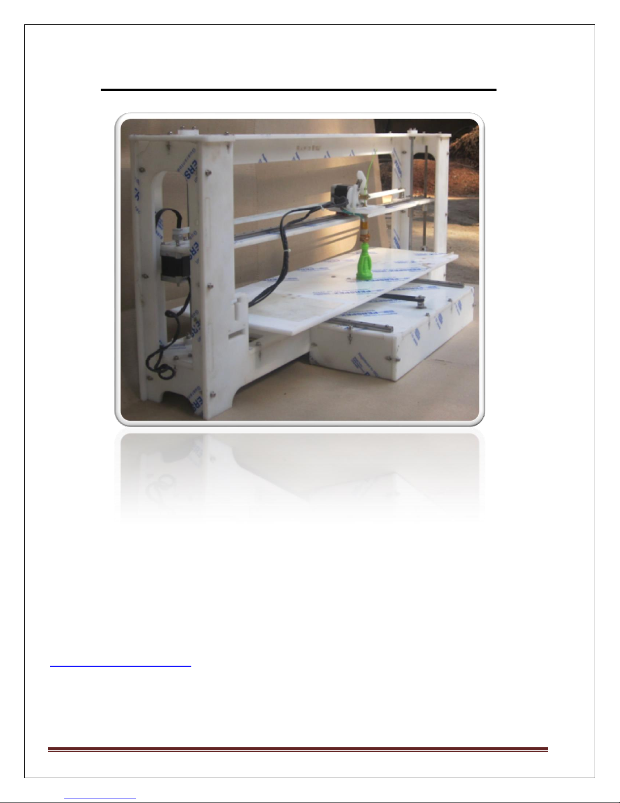
RapidBot Mega 3D Printer
RapidBot Mega is a latest generation 3D printer, capable of printing 3D objects of PLA plastic.
RapidBot Mega uses high quality Linear motion guides. So it is very easy to build. Self locking
design ensures rigid frame with easy steps(Without need of any measurements, during building)
Any person can easily build it by following our Manual.
If you have any queries or requests related to RapidBot Mega 3D Printer, Kindly drop a mail at :
support@makemendel.com, Our team will be ready to help you, and to answer your querries.
MAKE MENDEL Page 1
Page 2

Technical Specification :
• Machine size 900 x 350 x 500 mm
• Build size 750x250x200 mm
• Nozzle Diameter : 0.4mm
• Layer Thickness : 0.1 mm
• Speed (mm/s) : 60
• Positioning Precision : 27 microns
• Input Format : STL
• Software : Pronterface
• System Compatibility : Windows 7 and Vista
• Power Supply : ATX, 450W
• Weight : 25 Kg
Features :
1. It uses high quality linear motion guide.
2. Compact Design.
3. Printrboard and Power Supply are placed at the bottom to give clean and neat look.
4. Mechanically more Stable design.
5. Improved the PrintBed Adjustment.
6. Improved Extruder Design and Z axis.
7. Accurate and easy belt placement.
8. Large build volume with easy accessibility.
9. Uses high quality acrylic from:www.perspex.co.uk
10. Integrated power supply for both Printrboard and Heatbed.
11. Uses high quality aluminium pulley with T2.5 belts, to give high accuracy.
12. Self locking design ensures rigid frame.
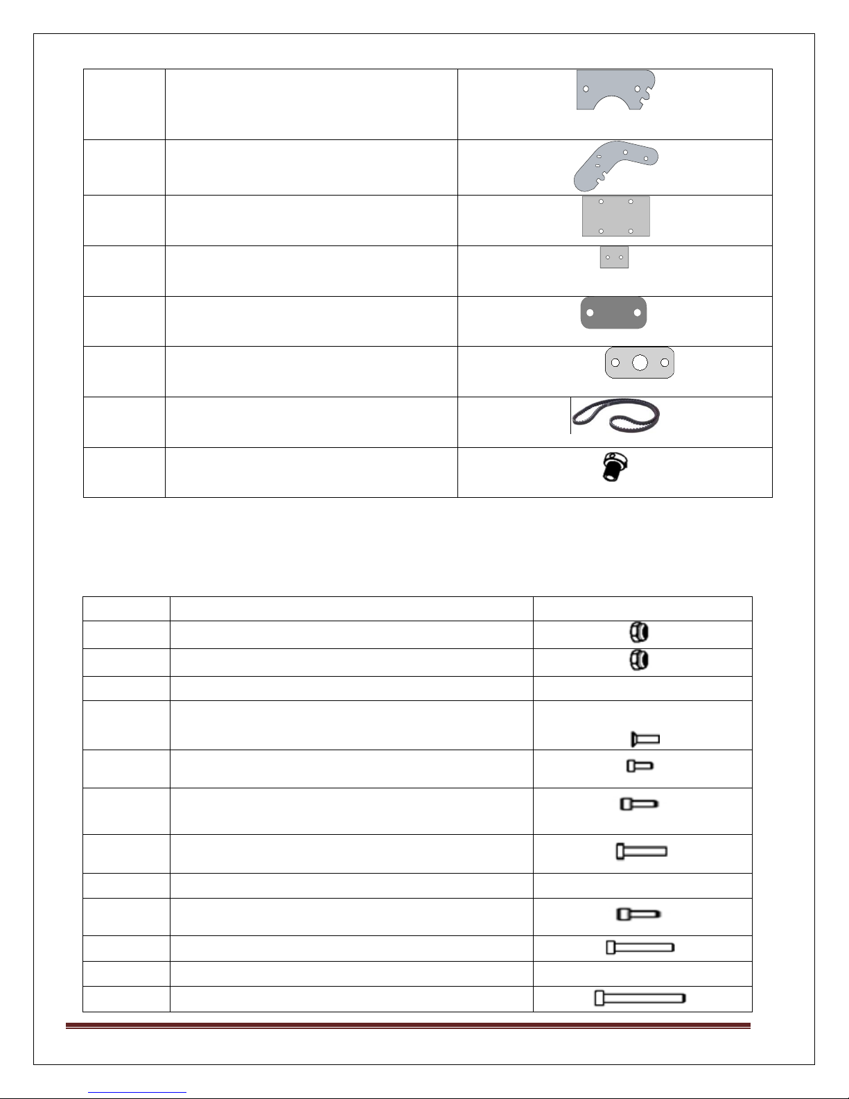
Part List For RapidBotMega Acrylic Sheets
MAKE MENDEL Page 2
Page 3

Qty
Part
Drawing
2
Side Plates
1
Middle Plate
1
Support plate for X plate
1
Front Plate
1
Back Plate
1
Top Plate
1
Y Kite support
1
Heated Print Bed
1
Aupport Plate for PCB Heatbed
1
Acrylic plate to connect two Y
Rails
1
Support for Y Plate
2
Support for Y Plate
3
Linear Motion(LM) Guide
1
Extruder Base
1
Extruder Motor Plate
MAKE MENDEL Page 3
Page 4
1
Driven Holder
1
Idler Holder
1
Y-Rail Top Plate
1
Acrylic support for Z Mechanical
switch
2
Smooth Rod Cap
2
Cap screw for smooth rod
2
X and Y Belts(GT2-700 mm)
4
Brass Insert piece
Qty
Part
Drawing
17
M3 Nylock Nut
40
M4 Nylock Nut
10
M2.5 Nut – & Screw Philips
4
M3 X 8 Philips Screw
22
M3 x 12 Socket Cap Screw
5
M3 x 15 Socket Cap Screw
17
M3 x 20 Socket Cap screw
4
M3 x 25 Counter Sink Cap Screw
14
M4 x 20 Socket Cap screw
19
M4 x 25 Socket Cap Screw
2
M4 x 25 Counter sink Cap Screw
2
M4 x 40 Socket Cap Screw
HARDWARE
MAKE MENDEL Page 4
Page 5

6
Screw for SMPS mounting
4
M2.5x20 Mechanical switch screw
&nut x & y switch for use
2
M2.5x25 Mechanical switch for z aliment
90
M3 Washer
70
M4 Washer
2
M4x10 Washer for mechanical switch
7
624-Bearing
2
Flange nut
2
Flange bearing
2
Coupling 5 _8
2
Soft Spring (1)(Extruder 2-Opto)
Hard spring (2)
1
Heat sink Paste
1
Dummy Rails
1
Forceps
1
FeviQuick
1
Plastic Tie
Qty
Part
Drawing
5
Stepper Motors-NEMA 17
HOTEND AND ELECTRONICS
MAKE MENDEL Page 5
Page 6

2
GT2 Timing Pulley_5mmBore (For X-Y Motor)
1
J HotEnd Extruder
3
Heater Blocks and Extra wire with Power
Connector
1
PTFE Strain Relief
1
Printrboard REV D Electronics Board
3
Mechanical switch with 3 pin Molex Connector
1
Z Prusa Cable
1
Resistor (3 watt 6.8 Ohm)
1
Thermistor G550 EPCOS
2
Teflon sleeve
2
4 pin and 2 pin Teflon Molex connector
1
Cooling Fan 60 x 60
1
USB Printer cable
1
Universal Travel Adaptor
1
Mini SMPS
2
Kapton Tapes (50mm + 15mm)
1
Magnetic Leveler
1
10m sample PLA
1
M8 Threaded Rod-285mm
2
M8 Threaded Rod of Spool Holder-125mm
2
Smooth Rod-292mm
MAKE MENDEL Page 6
Page 7
M2.5 Details
1
M2.5 Philips
Countersink Belts &
nuts(10)
Heated Print Bed (10)
2
M2.5x20 philips
Countersink
screw(4)
X & Y mechanical switch
3
M2.5x25
Countersink
screw(2)
Z mechanical switch
aliment
M3 Details
1
M3 Nylock(43)
LMG Rail (26)
Idler Excle (1)
Flange Bearing (8)
Flange Nut (8)
2
M3x8 Philips
Countersink (4)
Extruder base Plate (4)
3
M3 X 12 Socket Cap
(21)
Motor (X,Y,Z) (17)
SMPS(4)
4
M3x15 Socket Cap
(35)
LMG Rail (22) fitting
item
Extruder Motor (3)
5
M3 X 20 Socket Cap
(21)
Flange Nut (8)
LNG Rail Fitting (4)
623 Ugra Bearing (1)
Flange Bearing (8)
6
M3 x 25 Socket
Counter Sink Cap (4)
Print Bed (4)
7
M3 Nut (8)
LMG (2 at each end)
fitting (8)
8
M3 Washer (90)
LMG Rail (26)
Flange Bearing (16)
X-Y-Z Motor (16)
SMPS (4)
Flange Nut(16)
Extruder Motor Plate (8)
M4 Details
1
M4 Nylock Nut (40
Smooth Rod Cap (8)
Acrylic Side Fitting (26)
Bed Adjustment (2)
MAKE MENDEL Page 7
Page 8

Acrylic Base Plate Fitting
(2)
Z- Opto (1)
2
M4 x 20 Socket
Cap (14)
Acrylic Support (12)
Acrylic Base Plate (2)
3
M4x25 Counter
Sink (2)
294 mm Smooth Rod
Cap (6)
4
M4 X 25 Socket cap
(19)
300 mm Smooth Rod(6)
Acrylic Support(13)
5
M4 X 40 Socket cap
(2)
Belt Adjustment X,Y (2)
6
M4 X 20 Mudguard
Washer (4)
Belt Adjustment (4)
7
M4 Washer (80)
Main Structure Panel
(50)
624 Bearing Belt (11)
Extruder Motor Support
Plate (4)
Smooth Rod Cap (14)
Other Parts
1
624 Bearing (7)
X, Y Adjusting Belt (7)
2
623 Bearing (1)
Extruder Idler Holder
Part (1)
3
608 Bearing (2)
PLA Spool Holder (2)
4
M8 Nuts (12)
PLA Spool Holder
(8)
5
M6 Brass Nut (2)
Extruder (2)
6
Flange Nut (2)
Y Plate Threaded Rod
7
Flange Bearing (2)
Y Plate Smooth Rod
8
Smooth Rod Cap (4)
Smooth Rod Cap (4)
[Top Plate
Bottom Plate]
Note : How to Increase the build dimensions for Mega in Pronterface
1) Start ProntrFace
2) Go to Settings->Options->Set Build_dimensions to “750x250x165+0+0+0”.
3) Press Ok, and then close and restart the Prontrface
4) It will show you updated PrintBed grid.
MAKE MENDEL Page 8
Page 9

Assembly of Mega
MAKE MENDEL Page 9
Page 10

Part
Number
Name of Part
1
Back Plate
2
Aupport Plate for PCB Heatbed
3
Top Plate
4,5
Cap Screw for smooth rod
6
Acrylic plate to connect two Y Rails
7
X Plate
8
Extruder base Plate
9
Support plate for X plate
10, 11
Fan Support Piece
12,13,14
Acrylic piece use in Printbed assembly
15, 16
Cap screw for smooth rod
17
Y Plate
18
Side Plate
19
Front Plate
20,21
Support for Y Plate
22
Side Plate
23
Z-mechanical switch
24
Support for Y Plate
Picture 1.1
Index for Picture 1.1
MAKE MENDEL Page 10
Page 11

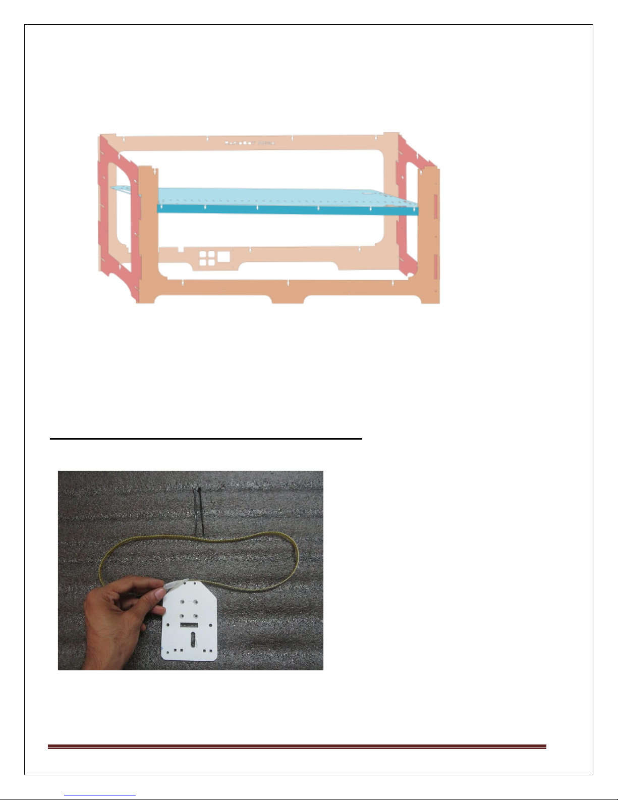
Step 1: Frame Assembly.
1. Assemble Front (Part No.19), back (Part No.1) and side (Part No.18 & 22) plates using M4 x
20 cap screws.
2. For Top plate to assemble with front, back and side plates use M4 x 25 screws.
MAKE MENDEL Page 11
Page 12

Assemble a set of 624 Bearings, M4x40 Socket, Mudguard, M4 washer, and M4
Nylock nut.
MAKE MENDEL Page 12
Page 13

Step 2: Y Plate
1. Part No: 17 is Y Plate. Fix three Motors (2Z and 1Y) using M3 x 12 Screws.
2. On Y plate place two small size rails along with block. Use M3 x 20 screws at both the corners
of each rail. Use M3 x 15 screws at the middle of each rail alternatively.
MAKE MENDEL Page 13
Page 14

3. Fix GT2 Pulley to the shaft of Y Motor and opposite to it place 624 bearing.
4. On Both the rails place acrylic piece (part no 12 & 14). Attach part no.13 with the GT2 belt
using ties. Fix the GT2 belt between GT2 pulley and 624 bearing.
MAKE MENDEL Page 14
Page 15

PTFE Stain Relief
Aluminium Printbed
Mechanical
Switch
5. Place Part no.6 on part no. 12, 13 & 14.
6. Use PTFE stain relief above part no.6.
7. Place aluminium printbed above PTFE stain relief. Use M2.5 x 20 screws for mechanical
switch to fix. Part no. 23 .
MAKE MENDEL Page 15
Page 16

8. Use M3 x 25 screws at each corner of aluminium printbed to set 1 and set 3. Use M4 x 25
countersink screws to fix set 2.
(Refer image of Step 6. for set 1, 2 & 3).
9. Use Part no. 20, 21 &24 to give support to Y plate at bottom side. Use M4 x 25 screws.
STEP 3: Z Mechanical Switch Assembly
1. Using Acrylic part and Screws given place the mechanical switch Under X
Motor, behind Threaded rod On Left side of the machine.
2. Assemble M4 Nylock, M4x40 Screw, Soft Spring, Washer and place above the
Mechanical switch to limit the switch.
MAKE MENDEL Page 16
Page 17

Step 4: X plate
1. Place Larger rail on X plate (Part No.7). Use M3 x 20 screw at the corner of rail Use M3 x 15
screws alternatively in the middle of rail.
2. Use flange nut at both the ends of Rail. Use M3 x 20 screws to fix the Flange nut.
3. Fix 2 flange bearings opposite to flange nut using M3 x 20 screws.
MAKE MENDEL Page 17
Page 18

4. Fix X-Motor using M3 x 12 screws. Fix T2.5 Pulley to the motor shaft.
5. Fix 624 bearing next to right flange bearing. Attach T2.5 Belt between T2.5 Pulley and 624
Bearing.
6. Place X mechanical switch using M2.5 x 20 Screws.
MAKE MENDEL Page 18
Page 19
7. Part No.9 is support to X plate. Use at Bottom side.
Attaching belt to the Extruder Base Plate:
1. Take the Extruder Base Plate, apply some glue on side face (this is not must), then just use
Plastic ties to tie it.
MAKE MENDEL Page 19
Page 20

2. Attach the Extruder base plate on the Rail Block.
3. Pass the T2.5 belt through the Pulley and Belt Adjuster.
Step 5: Assembly of Rods
1. Put the 2 Threaded rods inside the FlangeNut.
2. Place X-Axis inside the structure, by putting the bottom of the Threaded Rod inside the
Coupling.
3. Put the smooth rod inside the Flange Bearings. Use Caps Part no. 4,5,15 &16).
MAKE MENDEL Page 20
Page 21

SET 1
SET 2
SET 3
Solder to 4 Pin Molex connector.
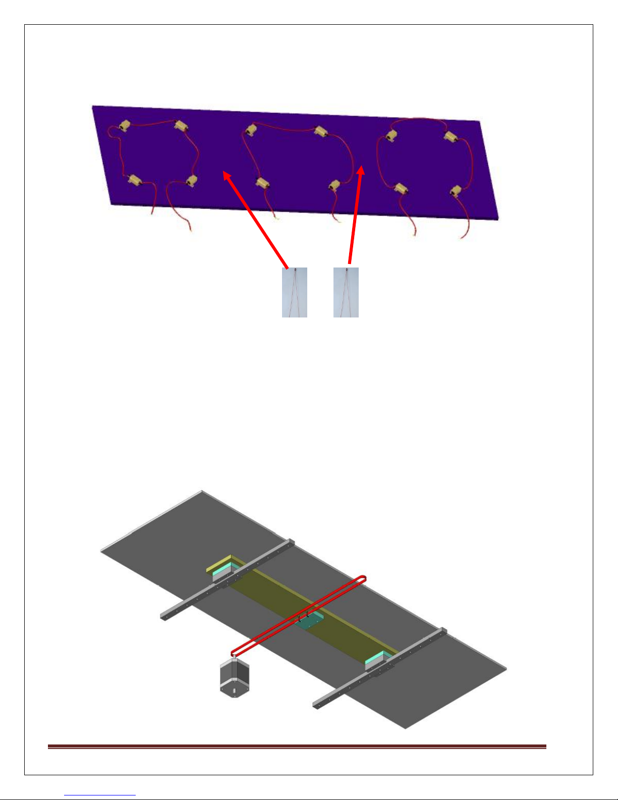
Step 6: Printbed assembly
1. Wiring of Heater Blocks :
First Place all the Heater blocks on Printbed as shown below. There are total 12 Heater
Blocks. Make 3 set of 4 heater blocks in each set.
Now connect each set of heater block in series. Leave one side of each set open for further
connection.
2. Solder wires of SET 1 with the 4 pin molex connector which will go to Printrboard.
MAKE MENDEL Page 21
Page 22

3. Solder the wires SET 2 and SET 3 to the female green connector given each.
4. In the ATX power supply cut yellow and black wires and solder it to male green connector given.
5. Now connect SET 2 & 3 female connector to the each male connector of ATX power supply.
MAKE MENDEL Page 22
Page 23
Solder wires of both thermistors to each other and
connect it to 2 pin connector which will go to Printrboard.
6. Place each thermistor at the centre of SET 1&2, SET 2&3 , and fix using kapton Tape.
7. Another ends of both the thermistors solder together to the 2 pin connector, which will go to
printrboard.
Final view of Printbed.
MAKE MENDEL Page 23
Page 24

STEP 7: Electrical wiring (Printrboard REV D)
Place PrintrBoard on Acrylic Board with Cap Screw M3x12
Cable connection on Printrboard.
MAKE MENDEL Page 24
Page 25

Steps to be followed while using Printrboard Electronics:
1. Check whether all the connections made on your Printrboard Board are proper.
2. Printrboard comes ready to print with Marlin RC 2 Firmware and LUFA CDC
BootLoader, So you do not need to change any firmware, if you have purchased entire
Rapidbot 3.0/Mega Kit from us.
3. Install Pronterface (With Slic3r) http://makemendel.com/support-1/downloads
4. Set Baud rate as 250000
5. Note: You have to connect the Hotend thermister to PrintrBoard, then this
“MinTemprature triggered” error will go away.
6. Remove the Boot Loader(Black) Jumper from the printrBoard, before connecting it
to the PC. The jumper is only needed only during the firmware update.
Front View
Printer Images :
MAKE MENDEL Page 25
Page 26

Back View
Left Side View
MAKE MENDEL Page 26
Page 27

Right Side View
MAKE MENDEL Page 27
 Loading...