

Page 1
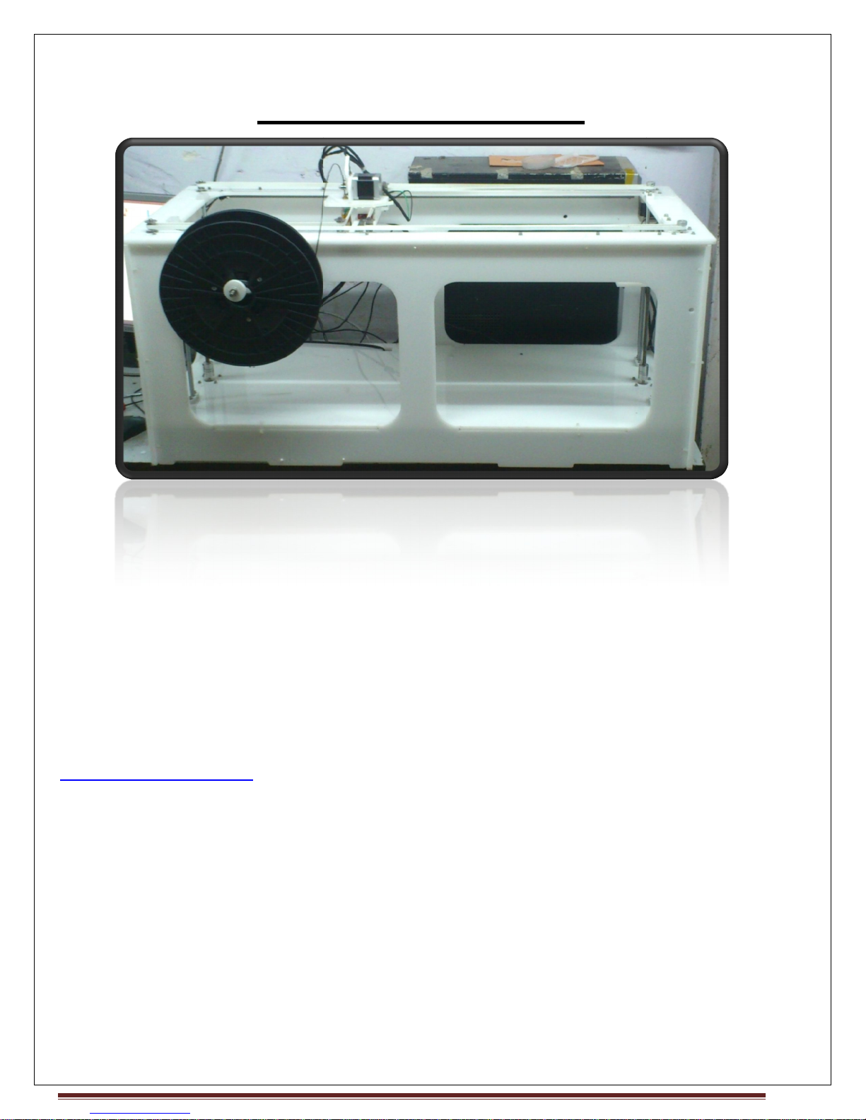
MegaBot
is a latest generation 3D printer, capable of printing 3D objects
uses high quality Linear motion guides. So it is very easy to build. Self locking design
ensures rigid frame with easy steps(Without need of any measurements, during building)
Any person can easily build it by following our Manual.
If you have any queries or requests related to
, Our team will be ready to help you, and
3D Printer
plastic.
3D Printer, Kindly drop a mail at :
answer your querries.
MegaBot
MegaBot
of PLA
MegaBot
to
MAKE MENDEL
Page 1
Page 2

Technical Specification :
• Machine size 400 x 1000 x 400 mm
• Build size 220 x 740 x 165 mm
• Nozzle Diameter : 0.4mm
• Layer Thickness : 0.1mm
• Speed : 60 mm/s
• Positioning Precision : 27 microns
• Input Format : STL
• Software : Pronterface (Available on site for free under Download section)
•System Compatibility : Windows 7 and Vista
• Power Supply : ATX, 450W
• Weight (Kg) : 32
Features :
1) It uses high quality linear motion guides.
2) LCD Controller Support
3) Acme Lead screw with nut
4) Spring Printrbed Adjustment, which keep Printbed more stable.
5) Printrboard and Power Supply are adjusted at the bottom to give clean and neat look.
6) Very easy to build, just 8-10 hours.
7) High quality aluminium pulley with T2.5 belts for Accurate and easy belt placement.
8) Large build volume with easy accesibility.
9) Uses high quality acrylic from http://www.perspex.co.uk
10) Self locking design ensures rigid frame with easy steps(Without need of any
measurements, during building).
MAKE MENDEL Page 2
Page 3
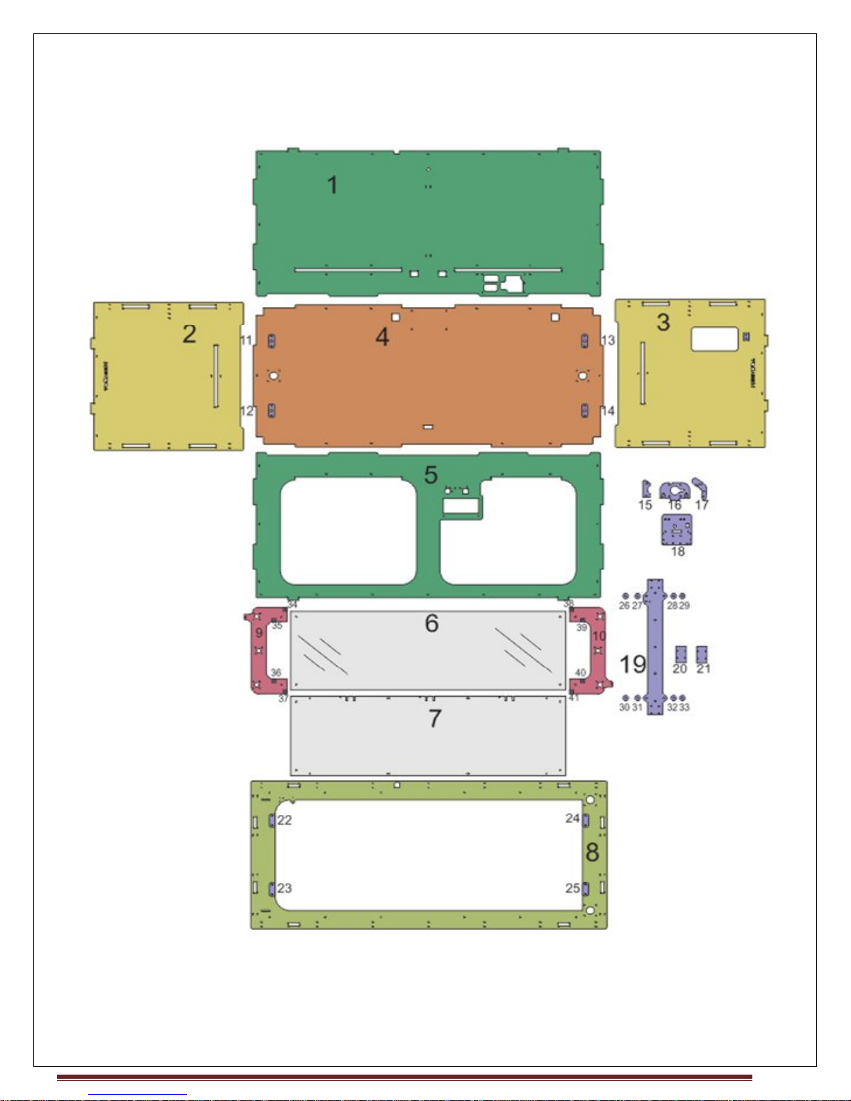
Assembly of MegaBot
MAKE MENDEL Page 3
Page 4
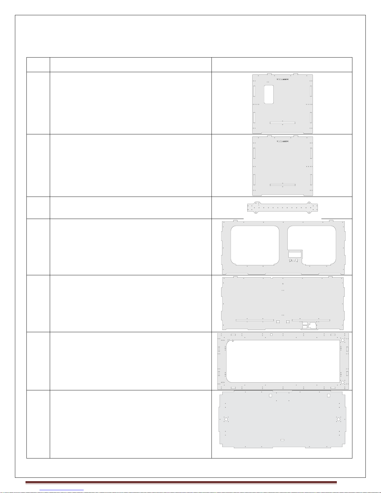
Part List For MegaBot-Acrylic Sheets
Qty Part Drawing
1 RightPlate
1 LeftPlate
1 XPlate
1 FrontPlate
1 BackPlate
1 TopPlate
1 BottomPlate
MAKE MENDEL Page 4
Page 5
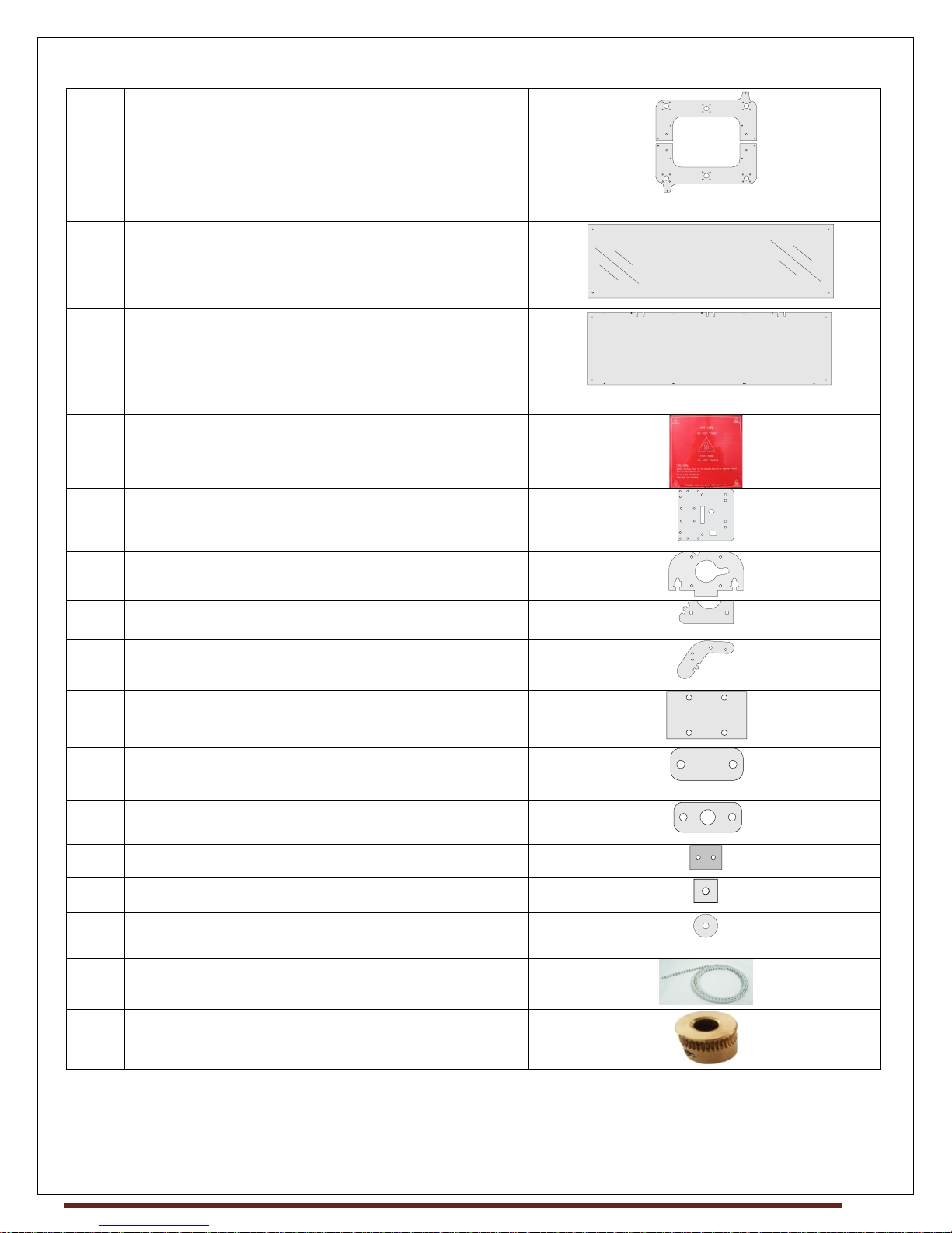
1 PrintBed-SupportPlate
1 GlassPrint Bed
1 AcrylicPrintBed
3 PCB HeatBed
1 ExtruderBasePlate
1 ExtruderMotorPlate
1 Driven Holder
1 Idler Holder
2 X-Rail Top Plate
4 TopSmoothRodCap(2 with Counter sink for
Front Side)
4 BottomSmoothRodCap
1 Acrylic Support for Z Mechanical switch
8 GlassSupportSquareBlocks
12 BearingSupport in XPlate
1 T2.5 Belt
1 MK7 Drive Gear
MAKE MENDEL Page 5
Page 6
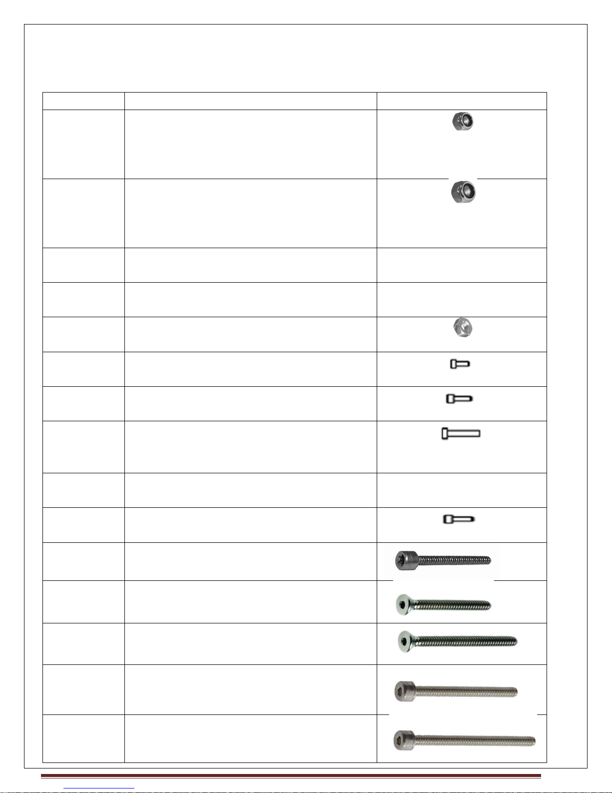
Hardware
Qty Part Drawing
57(36inBag+
21Attached)
M3 Nylock Nut
(16BigRail+ 8SmallRail, 16Flange
Bearing+8FlangeNut+ 1Extruder Idler+8
Glass support)
28 M4 Nylock Nut
(4 Belt idler+ 2 Belt Idler +
16SmoothRodCap+
2MotorMountingPlate+ 4PrintBed)
6 M2.5x20 Screw
(4Mechanical Switch+ 2LCD)
3 M2.5x25 Screw
(2Mechanical Switch+ 1LCD)
9 M2.5 Sada Nut,
(6Mechanical Switch+ 3LCD)
17 M3x12 SocketCap Screw
(Motor Mounting)
23 M3x15 SocketCap Screw
(20Rail + 3Extruder mounting plate)
31 M3x20 SocketCap screw
(16FlangeBearing+ 8FlangeNut + 6Rails +
1-623 Bearing)
12 M3x25 CounterSink
(4Extruder Base Plate+8GlassSupport)
2 M4 x20 SocketCap screw
(MotorMountingPlate)
12 M4x25 SocketCap Screw
(SmoothRodCap)
4 M4x25 Countersink Screw
(SmoothRodCap)
4 M4x50 CounterSink
(4PrintBed)
3 M4x40 SocketCap Screw
(2Belt Idleon TopPlate + 1ZSwitch)
4 M4x60 SocketCap
(Belt Idler)
MAKE MENDEL Page 6
Page 7
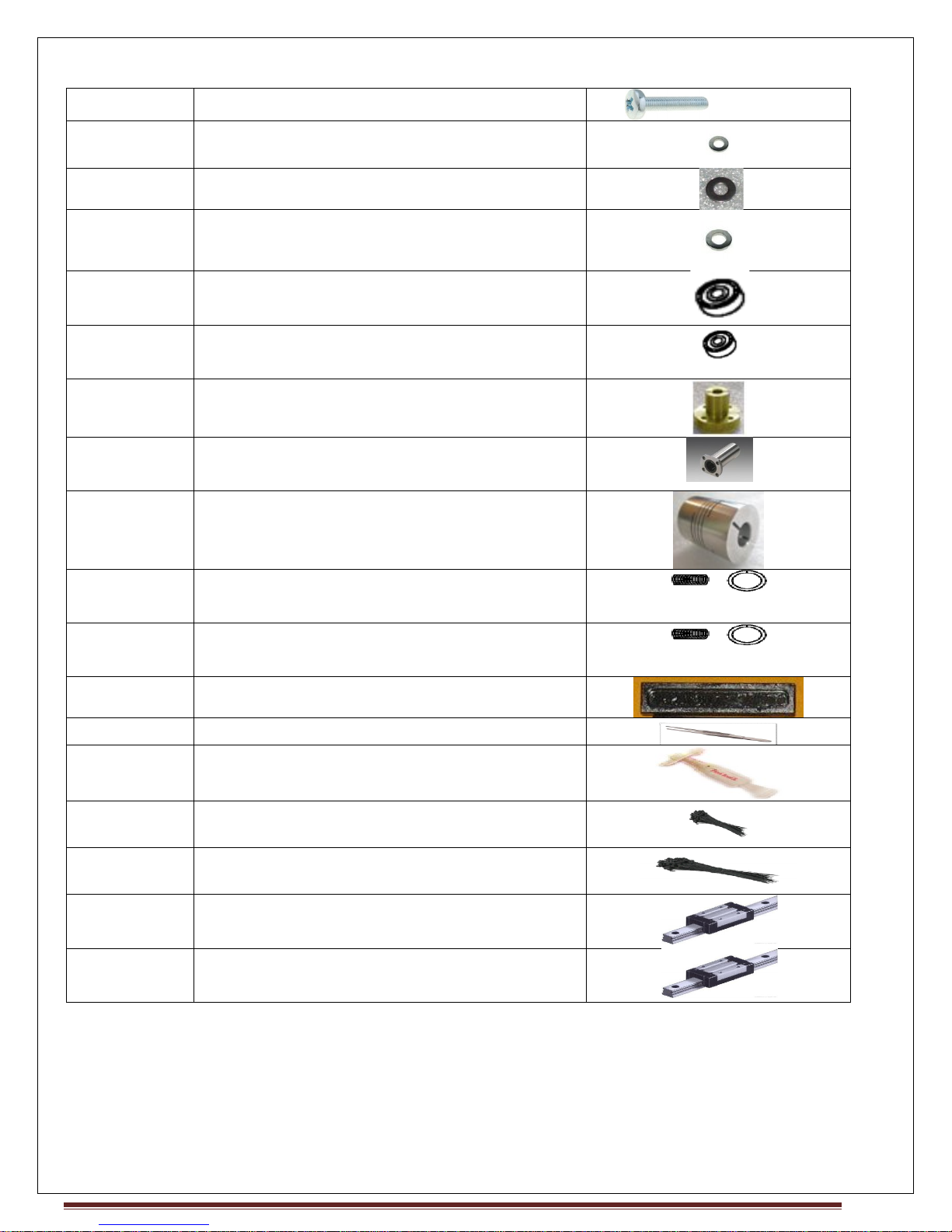
5 SMPS mountingScrew
103 M3 Washer
54 M4 Washer
14 M4x10 Washer
(12Belt Idler+ 2Z Mechanical switch)
22 624-Bearing
(Belt Idler)
2 623-Bearing
(Extruder)
2 Flange nut
4 Flange bearing
2 Coupling 5 _8
2 Soft Spring
(1Extruder+ 1ZSwitch)
4 Hard spring
(PrintBed)
3 Dummy Rails
1 Forceps
1 FeviQuick
35 Small Plastic Tie
35 Big Plastic Tie
1 Small Linear Motion Guide
(XAxis)
2 Large Linear MotionGuide
(2YAxis)
MAKE MENDEL Page 7
Page 8
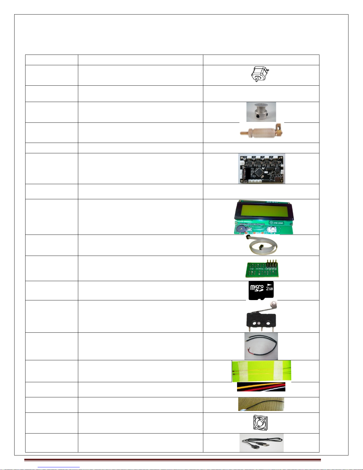
Hotend and Electronics
Quantity Part Drawing
5 Stepper Motors-NEMA 17
3 StepperMotor Extension Cable
2 T2.5 Timing Pulley_5mmBore(For
X-Y Motor)
1 J HotEnd with Cartridge heater
2 J-Hotend Extension Cable
1 Printrboard REV D Electronics
Board
1 Jumper for PrintrBoard
1 LCD
1 LCD flat cable
1 LCD connection PCB
1 Micro SD
3 Mechanical switch with 3 pin
Molex Connector
1 Z Prusa cable
1 Thermistor G550 EPCOS
2 Teflon sleeve
3 2 pin Teflon Molex connector
1 Cooling Fan 60 x 60
1 USB Printer cable
MAKE MENDEL Page 8
Page 9
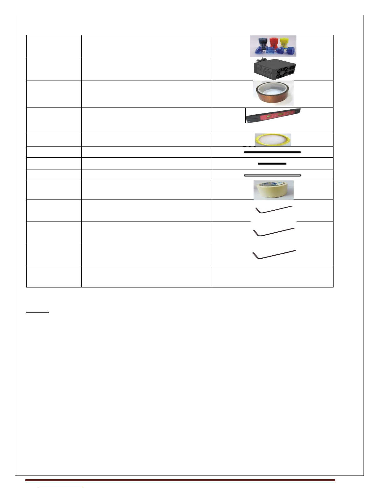
1 Universal Travel Adaptor
1 SMPS
2 Kapton Tapes (50mm + 15mm)
1 Magnetic Leveler
1 10m sample PLA
2 M8 Threaded Rod -285mm
1 Spool Holder-125mm
4 Smooth Rod(8mm Dia)-333mm
1 Paper Tape 50mm wide
1 Allan Key 2
(M4-GrubScrew, Pulley+MK7)
1 Allan Key 2.5
(M3 Socket Cap Head)
1 Allan Key 3
(M4 Socket Cap Head)
1 Wrench 5mm, 7mm
(For M3 and M4)
NOTE:
Dummy Rails: Dummy rails are given for maintenance purpose, if you will need in future. Be
careful while removing the LM block from the Rail. Put dummy rail on block before removing it.
4 pin Molex Connector: We give one extra.
Cooling Fan: Cooling Fan are needed for ABS , If you are using PLA there is no need of Cooling fan
Hotend: We provide are pre-solder Hotend
End Stops: When you press Print button, basically all 3 axis move to its HOME position. HOME
position is detected by Mechanical Switch. When switch is pressed, then printer understands that,
it has reached its home.
So there are 3 mechanical switch, 1 for each axis(X,Y,Z).
So, there is a Z Flag, which should go into the Z Optical switch, If z switch is moved during
shipping, then adjust it, so that it is pressed when nozzle is around 0.2 mm distance from
PrintBed..
MAKE MENDEL Page 9
Page 10
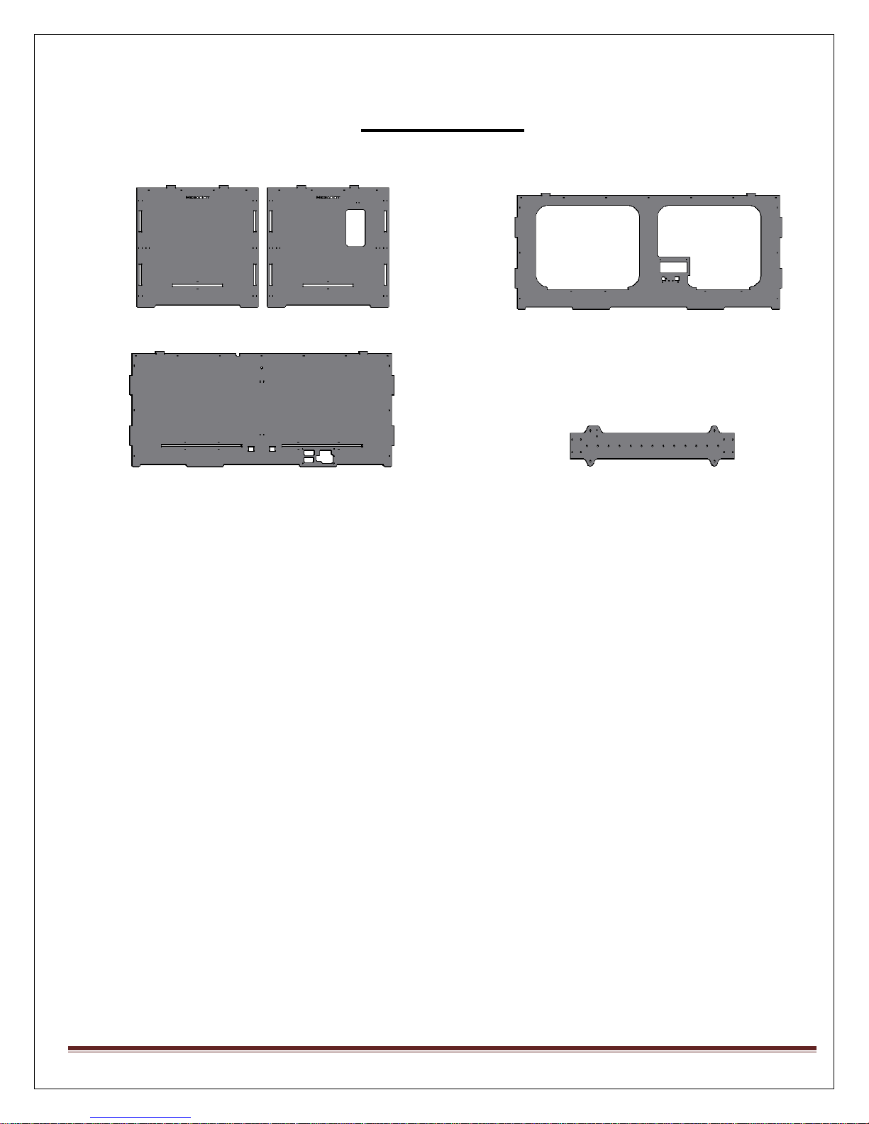
XPlate
List of Frames
2x Side Plates: Front Plate:
Back Plate :
MAKE MENDEL Page 10
Page 11
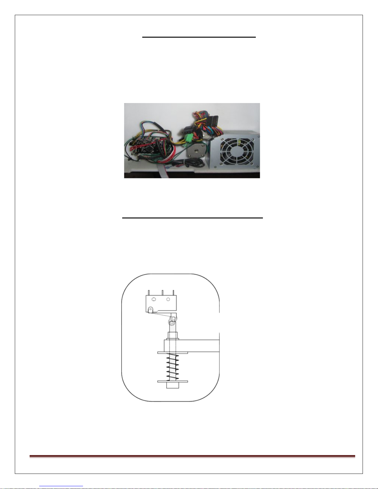
Assemble Bottom Plate :
1) Attach the Circuit board (Printrboard) at the bottom of the bottom-Plate, using Plastic
Ties.
2) Attach two Z motors at the Bottom plate.
3) Use Z Prusa cable to connect two Z motors, whose one end will go to Printrboard.
Z Mechanical Switch Assembly
1) Using Acrylic part and Screws (M2.5 x 25) given place the mechanical switch at the Side plate.
2) Assemble M4 Nylock, M4x40 Screw, Soft Spring, Mudguard Washer and place above the
Mechanical switch to limit the switch.
MAKE MENDEL Page 11
Page 12
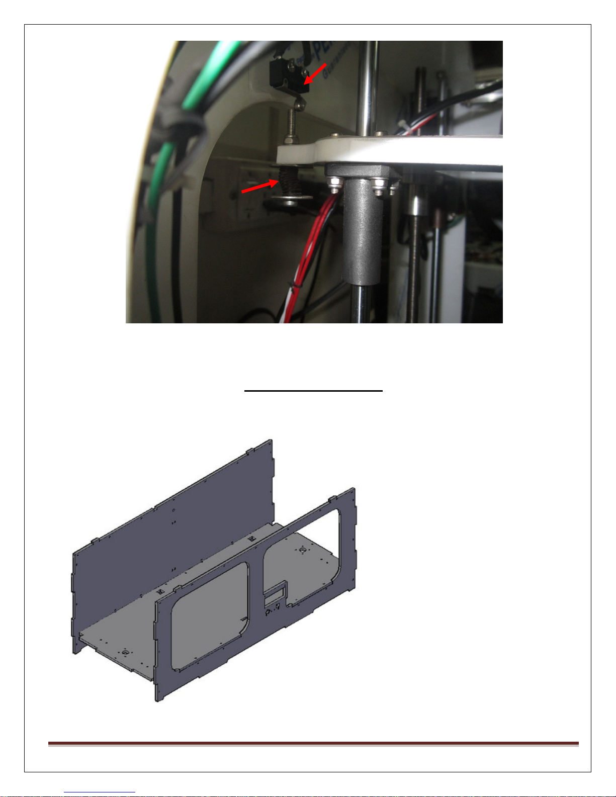
To Limit the
Mechanical Switch
Mechanical Switch
FRAME ASSEMBLY
Fix Two side plates with Bottom Plate Using plastic ties.
MAKE MENDEL Page 12
Page 13
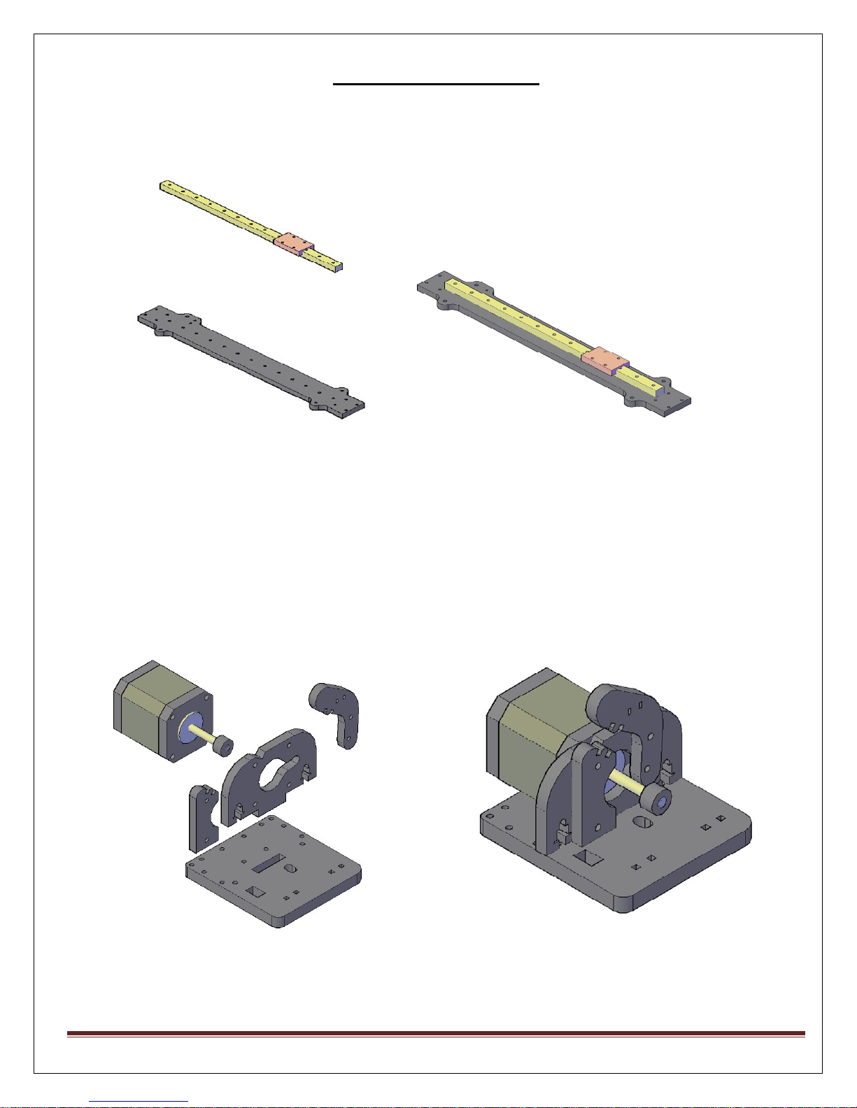
Assembly of X Plate
1. Now we will assemble X Plate.
2. Put Rail along with block on X Plate. Rail is pre assembly by our team.
3. Put two acrylic blocks on Rail Block.
4. On Top of that put the extruder, which is pre assembled. Use Screws to fix the
extruder on Rail.
MAKE MENDEL Page 13
Page 14
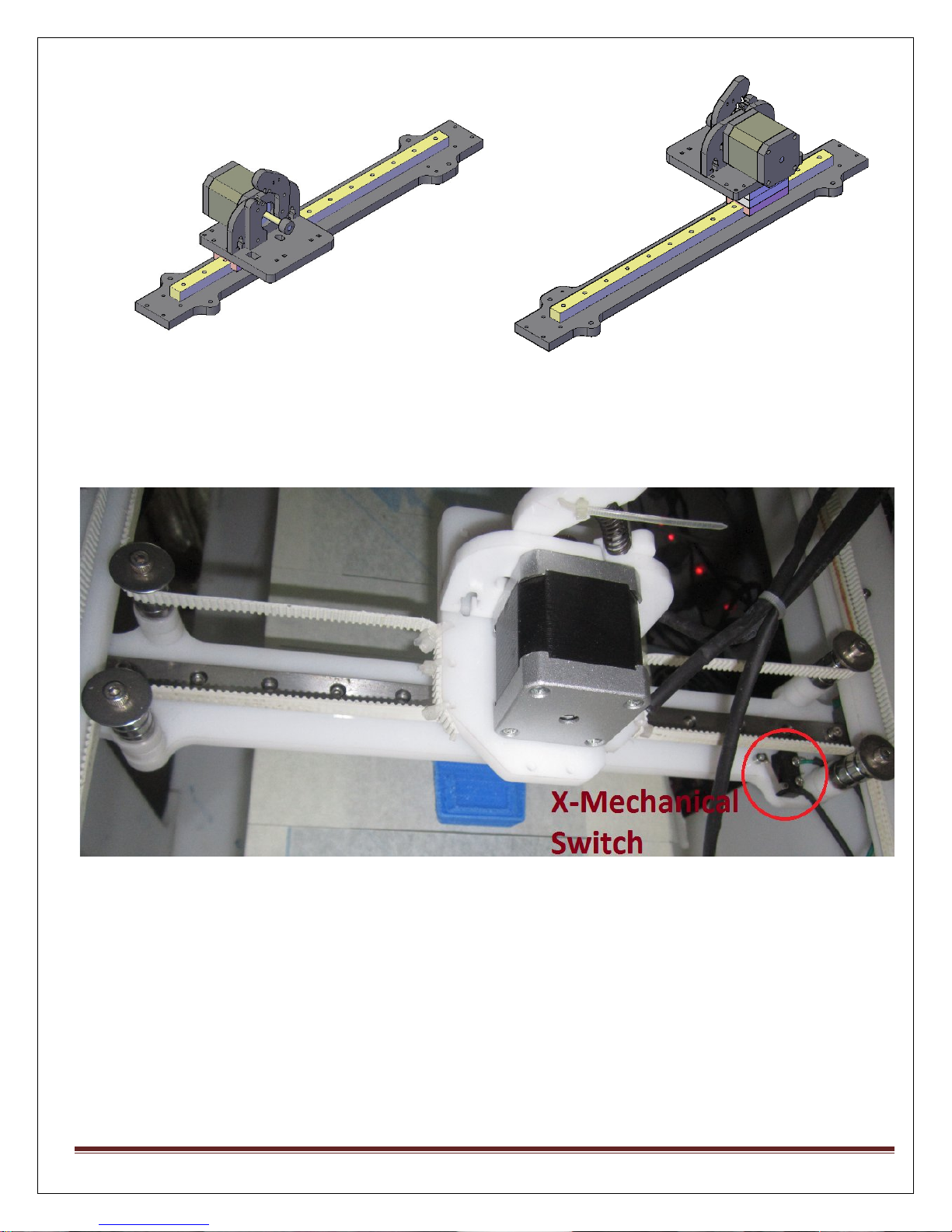
5. Now will assemble X Mechanical switch on X plate. Use M2.5 x 25 Screw to fix it at
proper place. Mechanical switch is soldered to two pin Molex already which will go
to Printrboard (X-STOP).
6. Your X Plate is readywith complete Extruder placed on it.
MAKE MENDEL Page 14
Page 15
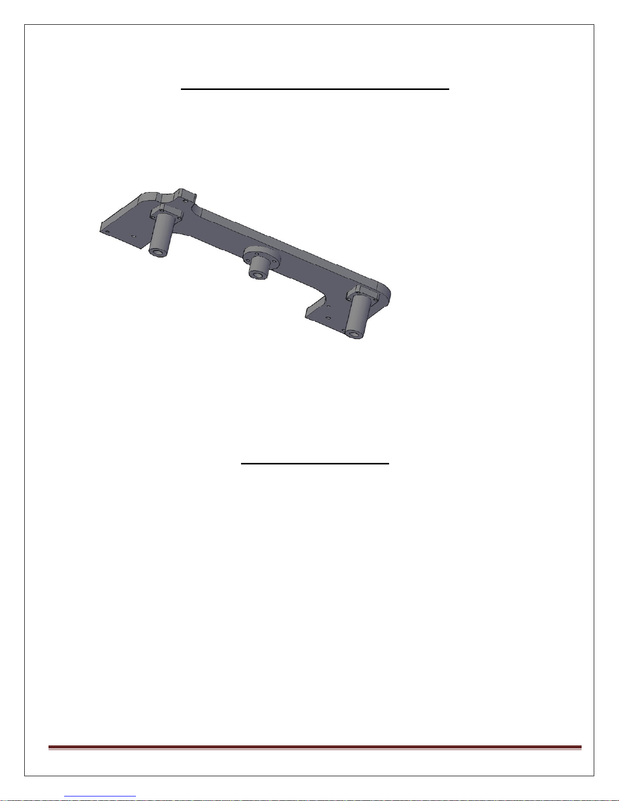
Assembly of Printbed Support Plate
1. Assemble Flange bearing at both corners of Printbed Support Plate using M3x20 Cap
Screws.
2. Fix the flange nut of Lead screw using
M3x20 Cap Screws.
3. Assemble the other side Support plate following step no.1 & 2.
4. Both Side Printbed Support plates are ready with us.
Assembly of Rods
1. Facing machine from front, rod assembly for left side as follows.
2. Put the coupling at the bottom side of Lead screw (8mm side). Other side of
coupling will be fixed in motor shaft (5mm side). Motor is already fixed on Bottom
plate.
MAKE MENDEL Page 15
Page 16
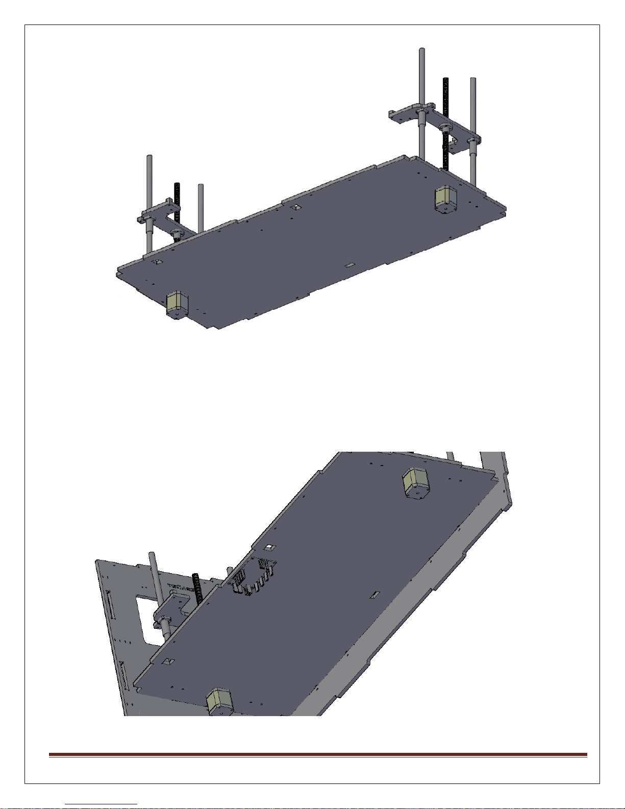
3. Place Lead screw (Threaded) at the center of Bottom plate. Place Smooth rods on
either side of lead screw. Fix the base of smooth rod in smooth rod caps using
screws.
4. Repeat step no.2 & 3 to do assembly of rods on right hand side.
5. Now your rods are fixed on Bottom plate.
MAKE MENDEL Page 16
Page 17
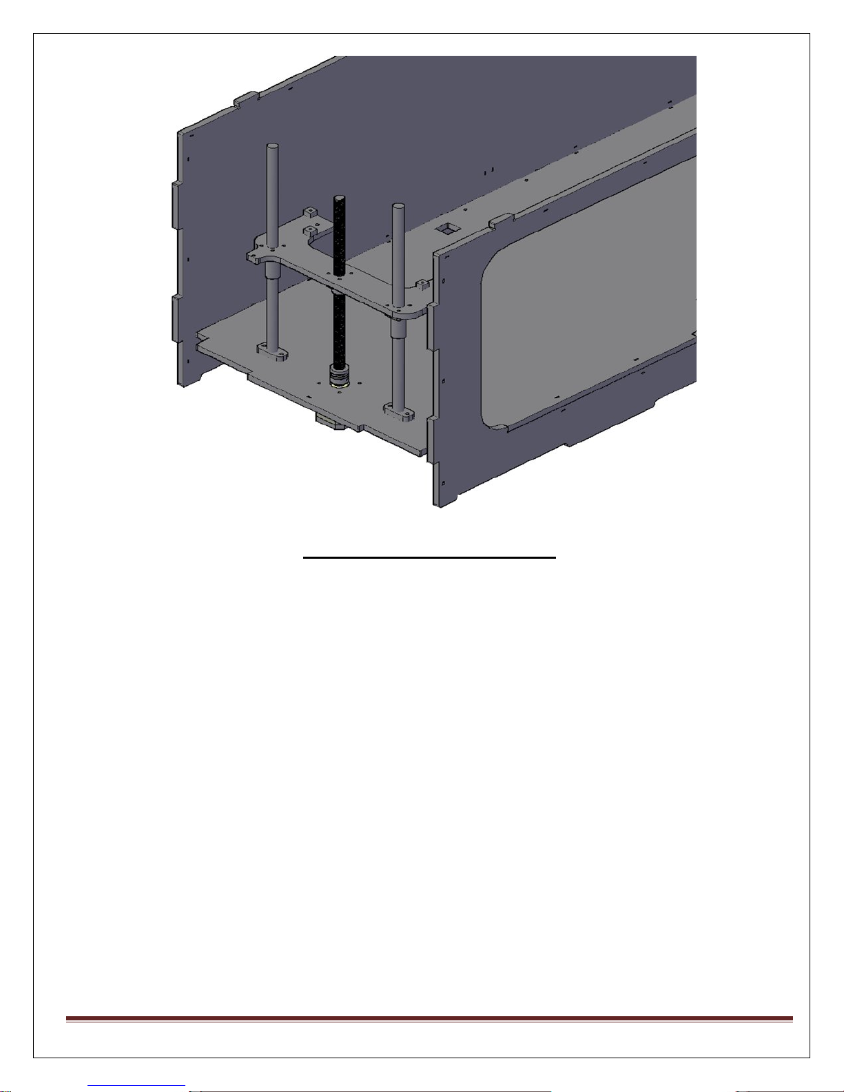
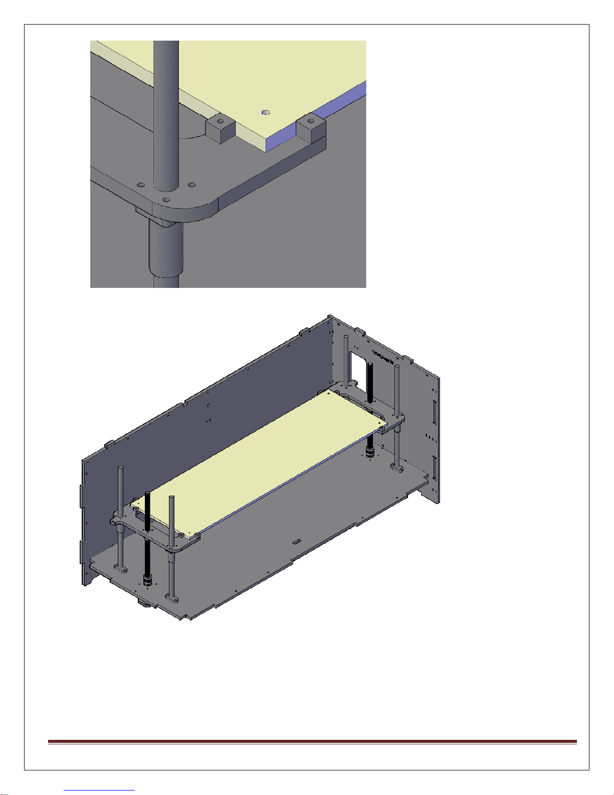
Glass Printbed Assembly
1. Place glass on Printbed Support plate. Be very careful with glass. Take your friends
help while fixing glass to hold it from other side.
2. Using plasticZiplock ties fix the Glass from all the 4 Corners.
3. Use the small 8 xacrylic Blocks given. They are to give support to glass printbed, so
that it will not shake and will keep the glass in a fix place.
4. Use plastic tiesto fix those 8 x small acrylic blocks.
MAKE MENDEL Page 17
Page 18
MAKE MENDEL Page 18
Page 19
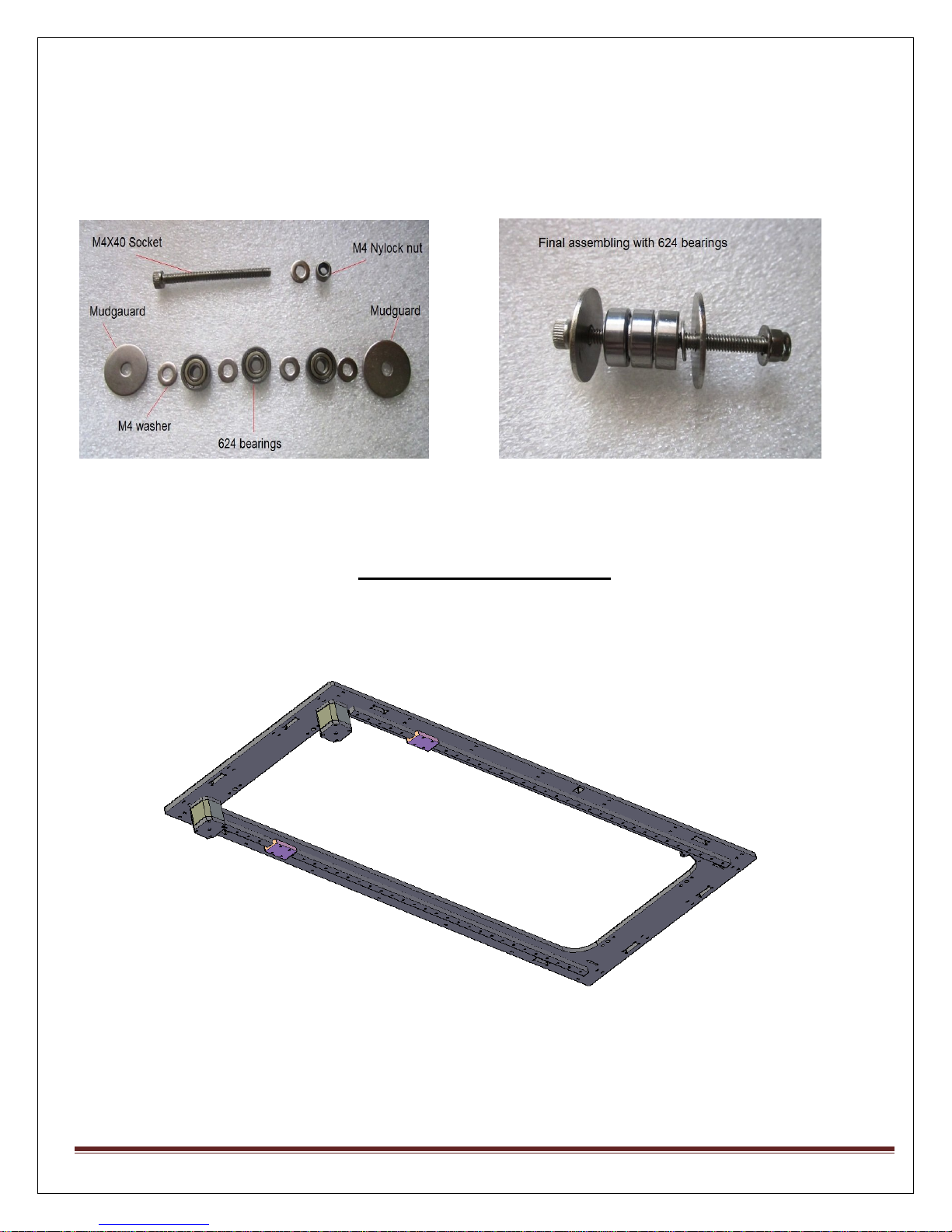
Before moving to Top plate assembly will keep the belt adjuster ready, so that belt placement
will be much handy.
Assemble a set of 624 Bearings, M4x40 Socket, Mudguard, M4 washer, and M4 Nylock nut.
Top Plate Assembly
1. Place the two motors at each corner of Top plate using M3 x 12 screws, fix T2.5
pulleys to the motor shaft.
2. On the Bottom side of Top plate fix rails using screws at the end of each rail, use
screws at alternative holes on rail to keep to properly place.
MAKE MENDEL Page 19
Page 20
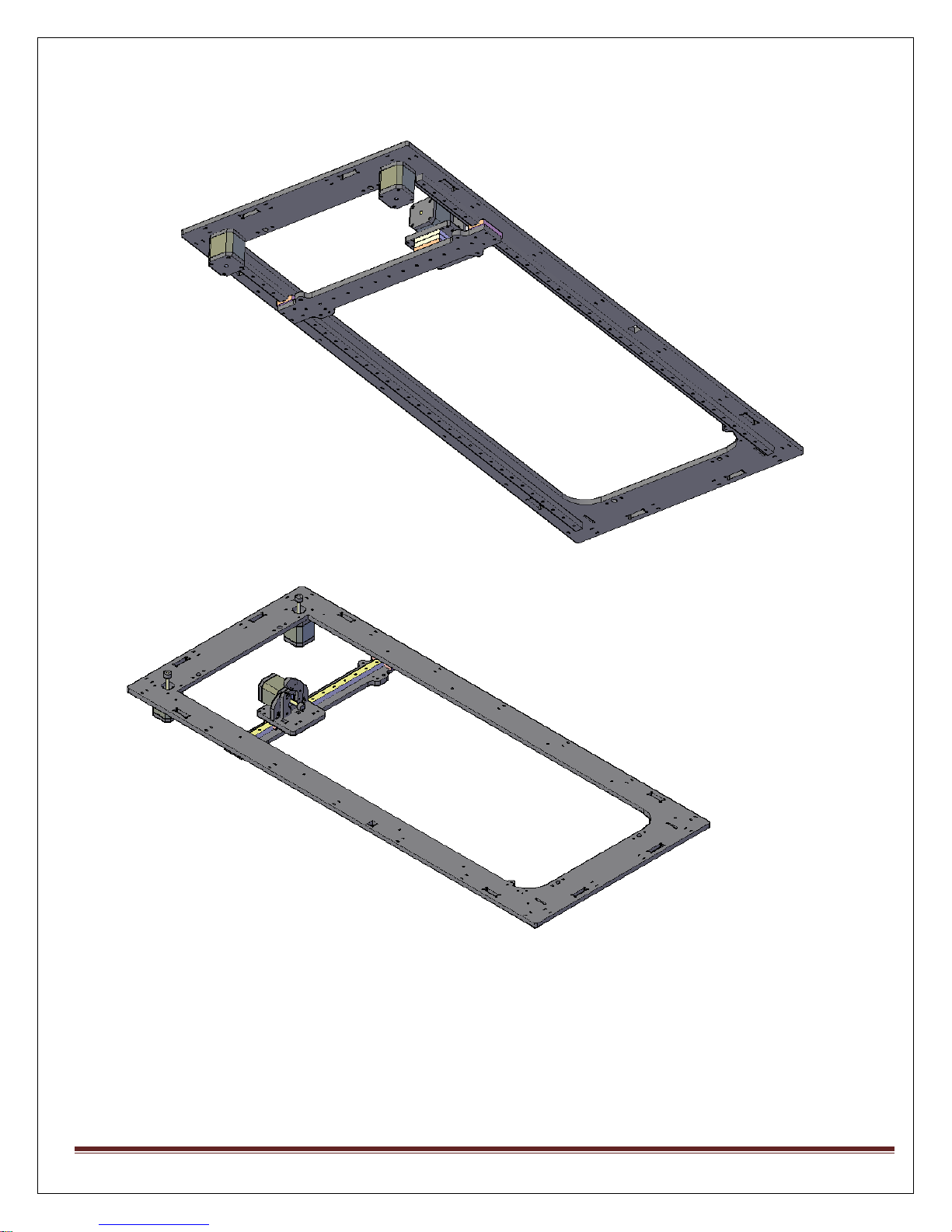
3. Turn around your Top plate, Put already assembled X plate on rail blocks. Use
screws to fix it. move X plate forth and back, just to check the Rapid movement.
MAKE MENDEL Page 20
Page 21
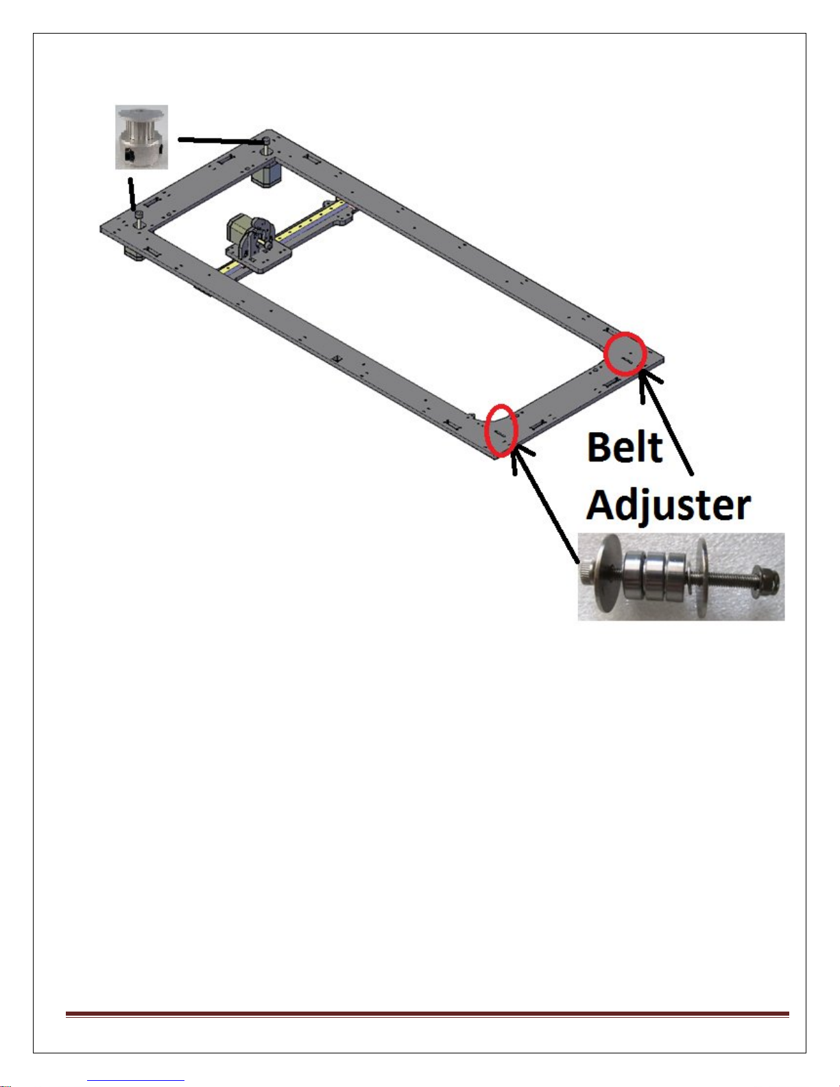
4. Place the belt adjusterand T2.5 Pulleyon Top plate. See below image for the places
where they should be placed.
5. Place Bearing stack on X plate. Use Bearing Support of X plate. They should be place
on four corners of x plate. 2bearing support at each corner.
MAKE MENDEL Page 21
Page 22
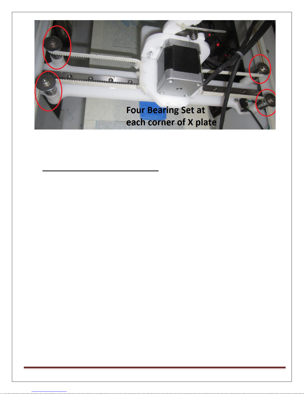
6. Now will assemble belt, follow the below sequence.
Attaching belt to the ExtruderBase Plate
1) Take the ExtruderBase Plate, apply some glue on side face (this is not must), then just use
Plastic ties to tie it. Start to fix the T2.5 belt from one side of Extruder base plate.
2) Complete the belt round through Pulley, belt Adjuster and Bearing stack at X plate and
finish it to opposite side of extruder base plate.
3) Attach the Extruder base plate on the Rail Block.
4) At the time of assembling belt Keep X plate at the center of Top plate, so that you can
judge how tight belt is to keep.
After Assembling of Complete Extruder
MAKE MENDEL Page 22
Page 23
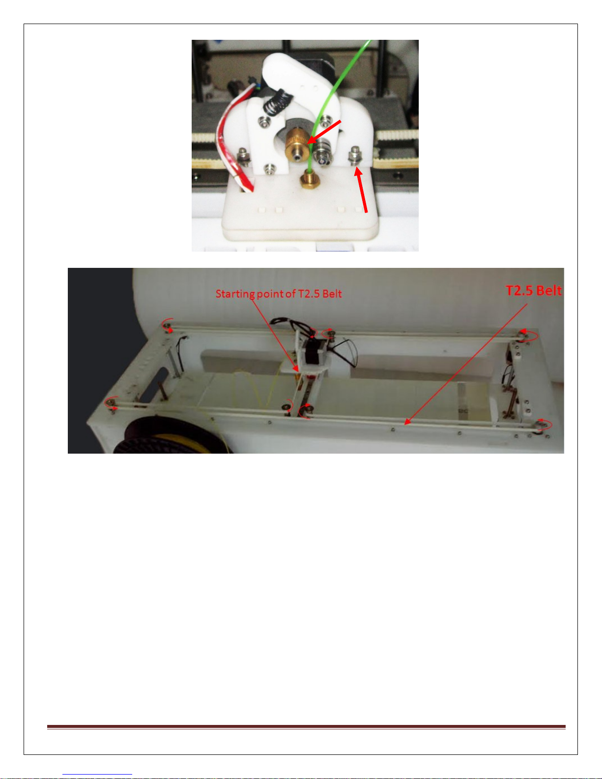
M4x20
Driver Gear
7. You are done with top plate assembly.
Now put all the frames together, Starting from Bottom plate.
Your frame with Rods , Glass Printbed is ready, Just put the top frame and your
machine is ready to print..
MAKE MENDEL Page 23
Page 24
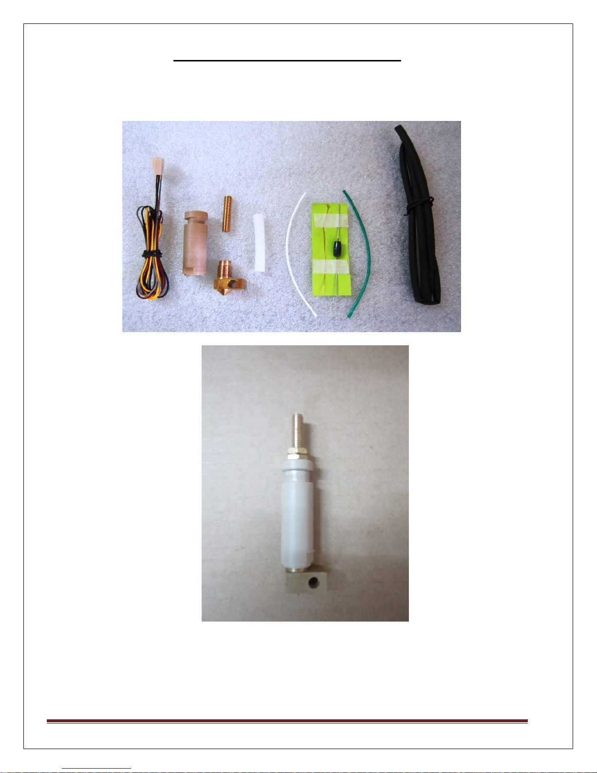
STEP 8 –J-HOTEND SOLDERING:
We have already, given you pre-soldered Hotend with the Kit. So you do not need to do
below steps.
MAKE MENDEL Page 24
Page 25
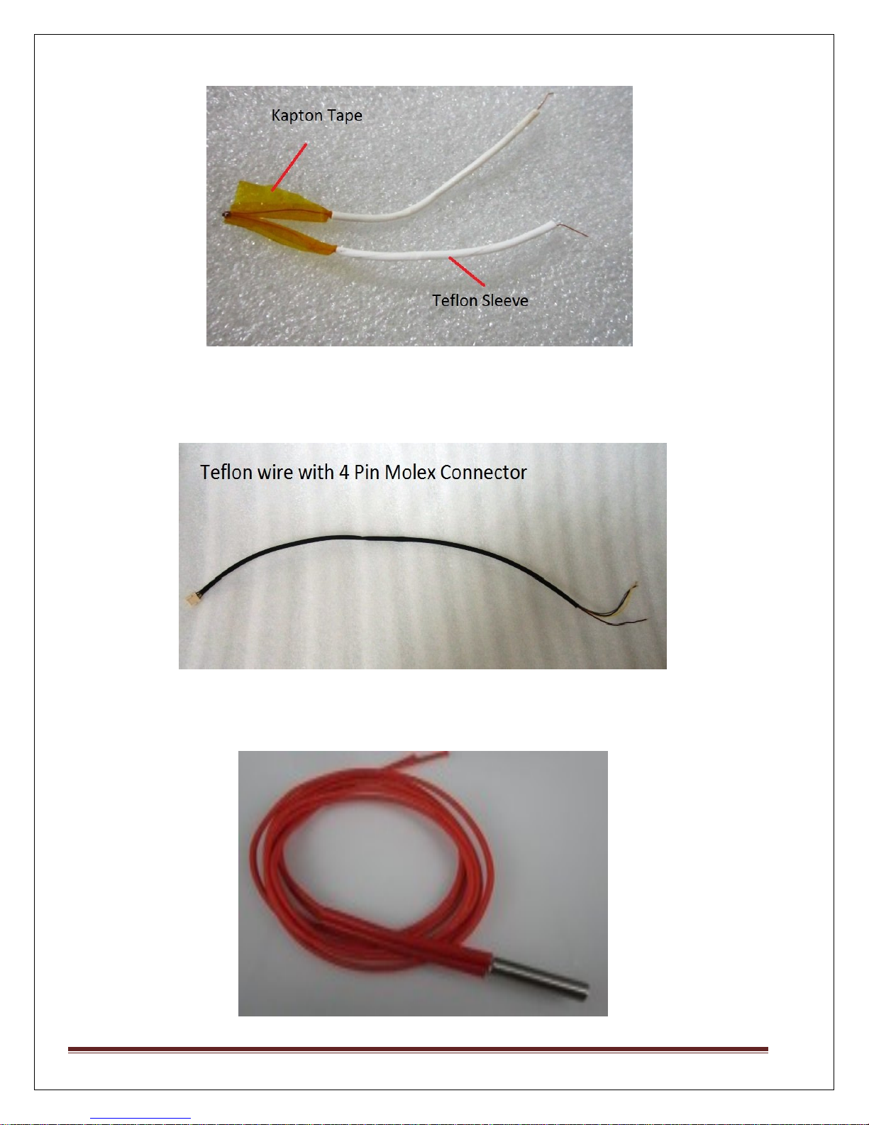
1) Thermistor with Kapton tape and Teflon sleeve
2) Teflon Wire with 4 Pin Molex connector
Solder the yellow and grey wire to resistor
Solder the Red wire to thermistor
MAKE MENDEL Page 25
Page 26
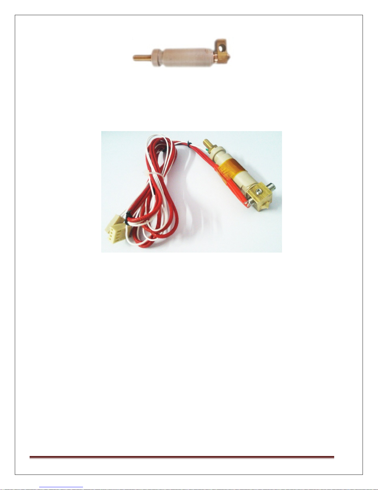
3) Use the silicon glue to fill the gap between resistor and brass block of hotend.
4) Final Assembling of J head hotend Extruder.
Note: Set Extuder Temperature to 185Degree, allow it to heat up to 180 degree then
only hit “Extrude” Button on Pronterfacesoftware. This will avoid clogging in Hotend
MAKE MENDEL Page 26
Page 27
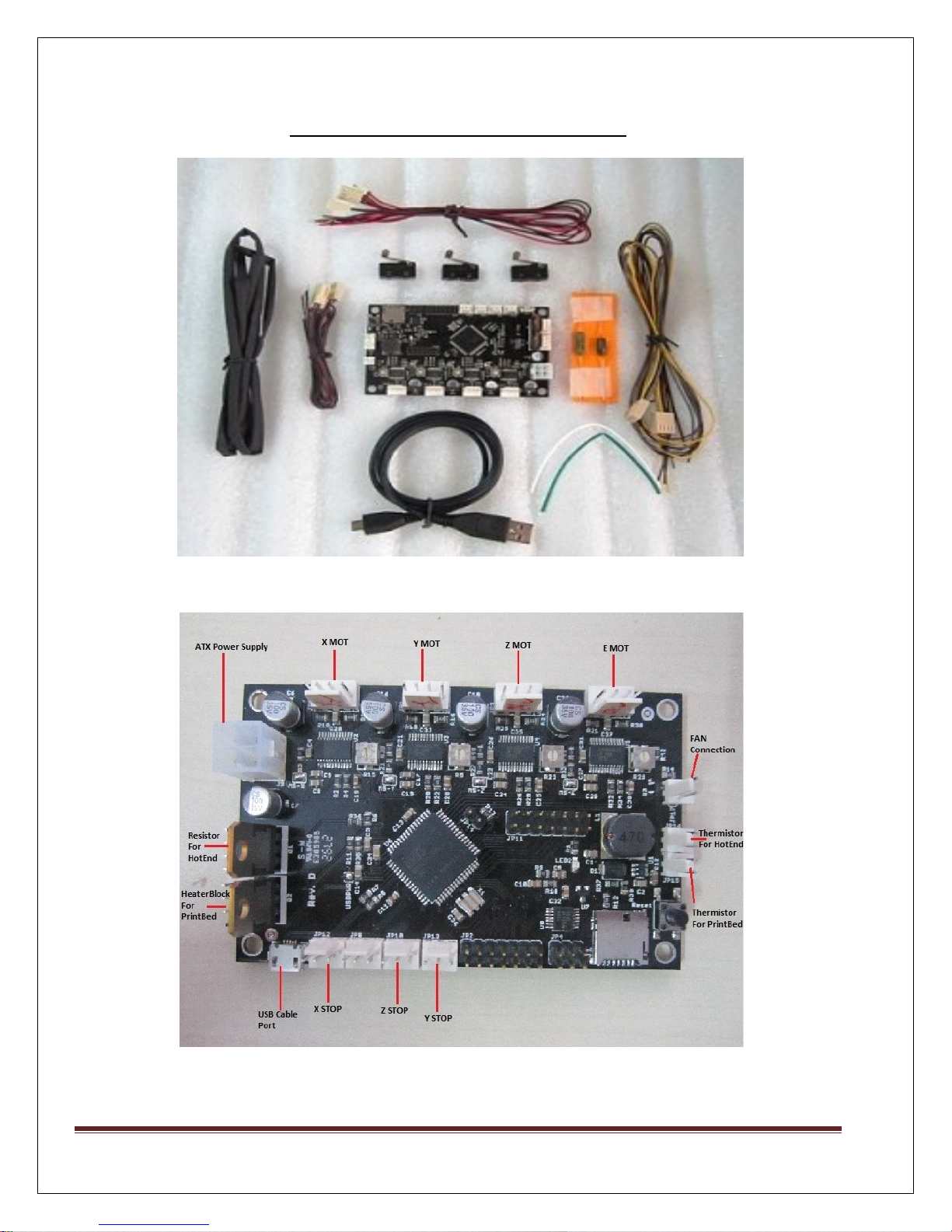
STEP 9: Electrical wiring (Printrboard)
Place PrintrBoard on Acrylic Board with Cap Screw M3x12
Connect the cables as shown above.
MAKE MENDEL
Page 27
Page 28
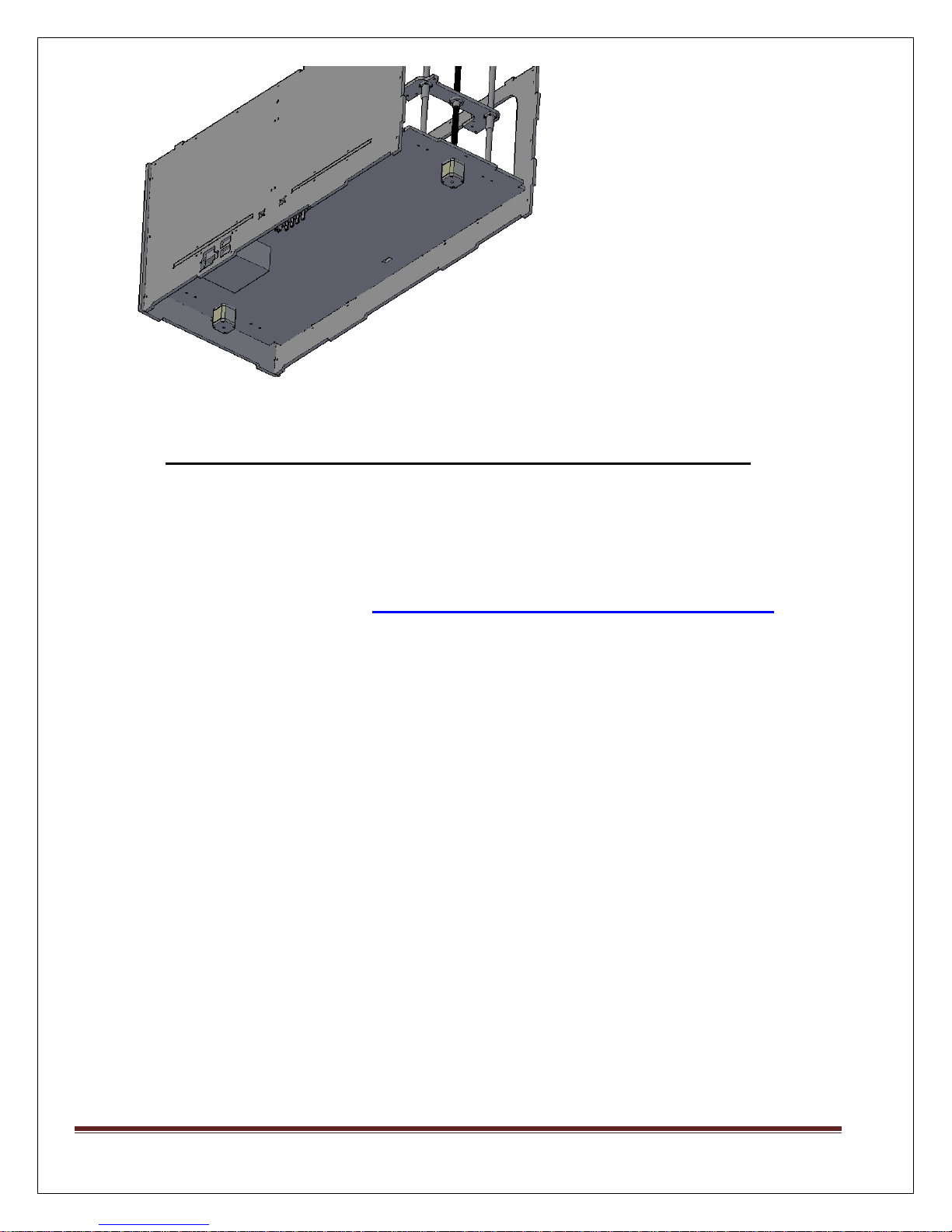
Steps to be followed while using Printrboard Electronics:
1. Check whether all the connections made on your Printrboard Board are proper.
2. Printrboard comes ready to print with Marlin RC 2 Firmware and LUFA CDC
BootLoader, So you do not need to change any firmware, if you have purchased entire
MegaBot/Orca Kit from us.
3. Install Pronterface (With Slic3r) http://makemendel.com/support-1/downloads
4. Set Baud rate as 250000
5. Note: You have to connect the Hotend thermister to PrintrBoard, then this “Min
Temprature triggered” error will go away.
6. Remove the Boot Loader(Black) Jumper from the printrBoard, before connecting it to
the PC. The jumper is only needed only during the firmware update
MAKE MENDEL
Page 28
Page 29
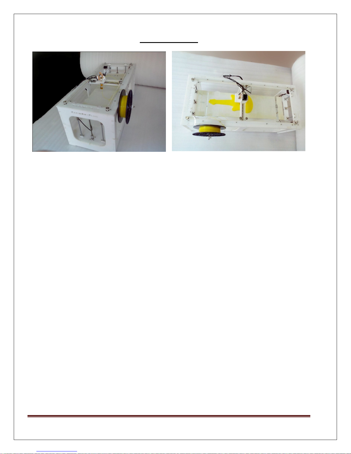
Printer Images:
MAKE MENDEL
Page 29
 Loading...