

MAKELSAN SE SERIES, SE906S, SE906H, SE9010HSE9015H, SE9020H User Manual
...
USER MANUAL
POWERPACK SE SERIES
6 - 20 KVA

POWERPACK SE SERIES 6-20 kVA CONTENTS
USER MANUAL
POWERPACK SE SERIES
6 - 20 KVA
UDD-SD-112
2
POWERPACK SE SERIES 6-20 kVA CONTENTS
About The Manual
This manual is prepared for the users of Powerpack SE Series 6-20 kVA.
Companion Manuals
For further information about this device and its options, please visit www.makelsan.com.tr
Updates
Please visit www.makelsan.com.tr for updates. Always use the latest manuals.
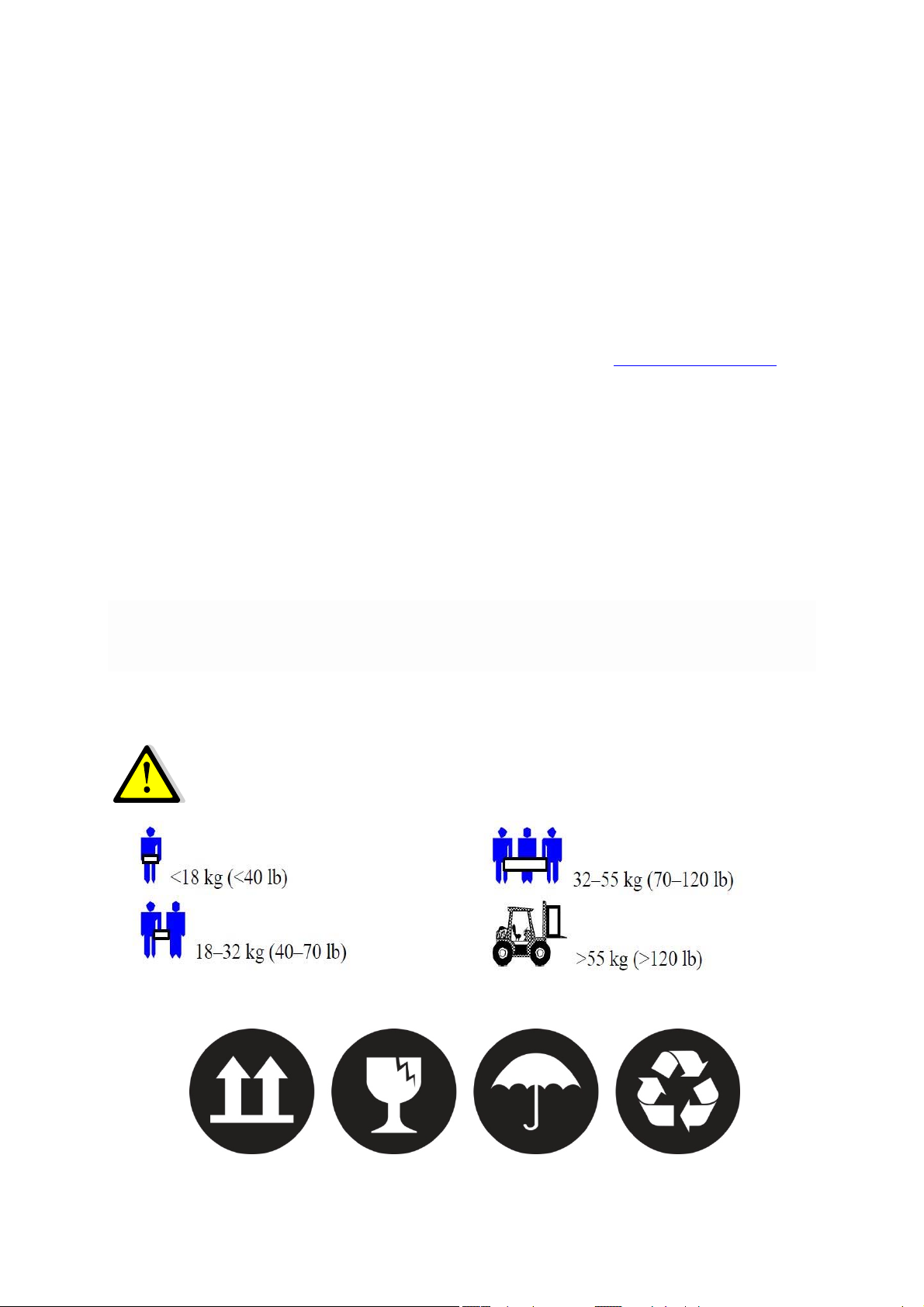
Shipment
Carrying vehicles or handling accessories must have enough features and characteristics to carry
UPS’s weight.
DO NOT LIFT HEAVY DUTY WEIGHT WITHOUT HELP
Be more careful of sudden movements, especially when batteries are inside of cabinet.
3

POWERPACK SE SERIES 6-20 kVA CONTENTS
CONTENTS
1 SAFETY INSTRUCTIONS .............................................................................................................................................. 6
1.1 UPS Safety Instructions ........................................................................................................................................ 6
1.2 Battery Safety Instructions ................................................................................................................................ 6
2 FEATURES ......................................................................................................................................................................... 7
2.1 Unpacking Inspection ........................................................................................................................................... 7
2.1 UPS Rear Panel View ............................................................................................................................................. 8
3 INSTALLATION INSTRUCTIONS .............................................................................................................................. 9
3.1 Attention items of Installation .......................................................................................................................... 9
3.2 Output Connection .............................................................................................................................................. 10
3.3 Parallel System of 6-20K UPS Installation ................................................................................................ 11
3.3.1 Parallel System Installation ........................................................................................................................ 11
3.3.2 Parallel System Operation and Maintenance ....................................................................................... 14
3.4 External Battery Connection Procedure for Long Back up Type ..................................................... 15
3.5 Network Functions ............................................................................................................................................. 16
3.5.1 Communication Port ...................................................................................................................................... 16
3.5.2 EPO Port .............................................................................................................................................................. 17
3.5.2 Intelligent Card (Option) .............................................................................................................................. 17
3.6 Maintenance Switch (Option) ........................................................................................................................ 18
3.7 Battery Pack Selecting ....................................................................................................................................... 19
4 PANEL FUNCTION and OPERATION ................................................................................................................... 20
4.1 Keys Function ....................................................................................................................................................... 20
4.2 LED Function .................................................................................................................................................... 21
4.3 LCD Display Function .................................................................................................................................... 21
4.4 Single UPS Turn On/Off Operation .......................................................................................................... 23
4.4.1 Turn On Operation ...................................................................................................................................... 23
4.4.2 Turn Off Operation ..................................................................................................................................... 23
4.5 Single UPS Self-Test/Mute Test Operation ........................................................................................... 24
4.6 Single UPS Panel Function Setting ........................................................................................................... 24
4.6.1 ECO Mode Setting ........................................................................................................................................ 24
4.6.2 Input Methods Setting ............................................................................................................................... 25
4.6.3 Output Voltage Setting .............................................................................................................................. 25
4

POWERPACK SE SERIES 6-20 kVA CONTENTS
4.6.4 Low Battery Voltage Shutdown Point Setting ................................................................................. 26
4.6.5 Frequency Converter Mode Setting ..................................................................................................... 27
4.6.6 Output Frequency Setting in CUCF Mode .......................................................................................... 28
4.6.6 ID Setting ........................................................................................................................................................ 28
4.7 Parameters Inquiring Operation .............................................................................................................. 29
5 WORKING MODE INTRODUCTION ...................................................................................................................... 31
5.1 Bypass Mode ......................................................................................................................................................... 31
5.2 Line Mode ............................................................................................................................................................... 31
5.3 Battery Mode ......................................................................................................................................................... 31
5.4 ECO Mode ............................................................................................................................................................... 32
5.4 Fault Mode.............................................................................................................................................................. 32
6 THE WARNING CODE LIST OF THE LED LIGHT and DISPLAY PANEL.................................................. 33
7 TROUBLE SHOOTING ................................................................................................................................................. 36
8 GUARANTEE .................................................................................................................................................................. 41
8.1 Terms of Guarantee ............................................................................................................................................ 41
8.2 Cases Not Covered by the Guarantee .......................................................................................................... 42
9 CONTACT INFORMATION ........................................................................................................................................ 45
5

1 SAFETY INSTRUCTIONS
1.1 UPS Safety Instructions
Before applying the UPS system, Please read through all safety information and operating
instructions carefully. It’s recommended to save this manual properly for future reading.
Do not install the UPS system near the water or in moist environments.
Do not install the UPS system where it would be exposed to direct sunlight or near the heater.
Place the UPS staying away from the wall for some distances, ensure enough space on each side
of UPS, do not block ventilation holes in the UPS housing. Install it by following the instructions
in the manual.
Please do not open the UPS case as you will, there is a high risk of electric shocks inside.
Do not connect to the equipment like hair dryer or electric heater, to ensure the safety for the
UPS.
Do not use liquid extinguisher if there is a fire, a dry powder extinguisher is recommended.
Attention:
UPS has high voltage inside, for personal safety, please do not repair by yourself. If any
questions, please contact local service center or dealer.
1.2 Battery Safety Instructions
Battery life cycle will be shortened as environment temperature rise. Replacing battery
periodically can help to keep UPS in normal state and assure backup time required.
Battery replacement should be done by authorized technician. If you want to replace the
battery cable, please purchase it from our local service center or distributors to avoid fever and
lighter which can cause fire from inadequate power capacity.
Batteries may cause electric shocks and have a high short-circuit current, for human being
safety, please follow the specifications as below when replace the batteries:
o Remove wristwatches, rings and other metal objects
o Use only tools with insulated grips and handles
o Wear insulated shoes and gloves
o Do not put the metal tools or parts on the battery
o Before disconnecting the terminals on battery, please cut off all the loads to battery first.
Do not dispose of the batteries with fire so as to avoid explosion.
Don’t open the battery, electrolyte inside will do harm to eyes and skin. Please use plenty of
clean water to wash if touching and go to see a doctor.
Do not connect the positive pole and negative pole directly, otherwise it cause electric shocks
or will be on fire.
The battery circuit is not isolated from the input voltage, high voltage may occur between the
battery terminals and ground, before touching, please verify no voltage is present.
UDD-SD-112/ Release Date: 25.12.2014/Rev No: 1 /Rev. Date: 18.05.2015
6
2 FEATURES
2.1 Unpacking Inspection
Open the UPS package, please check the enclosed accessories including user manual, RS232
communication cable, USB cable and CD-ROM.
Check the UPS if anything damaged in transport. If find something damaged or parts missing,
do not power on, please turn to the carrier and dealer.
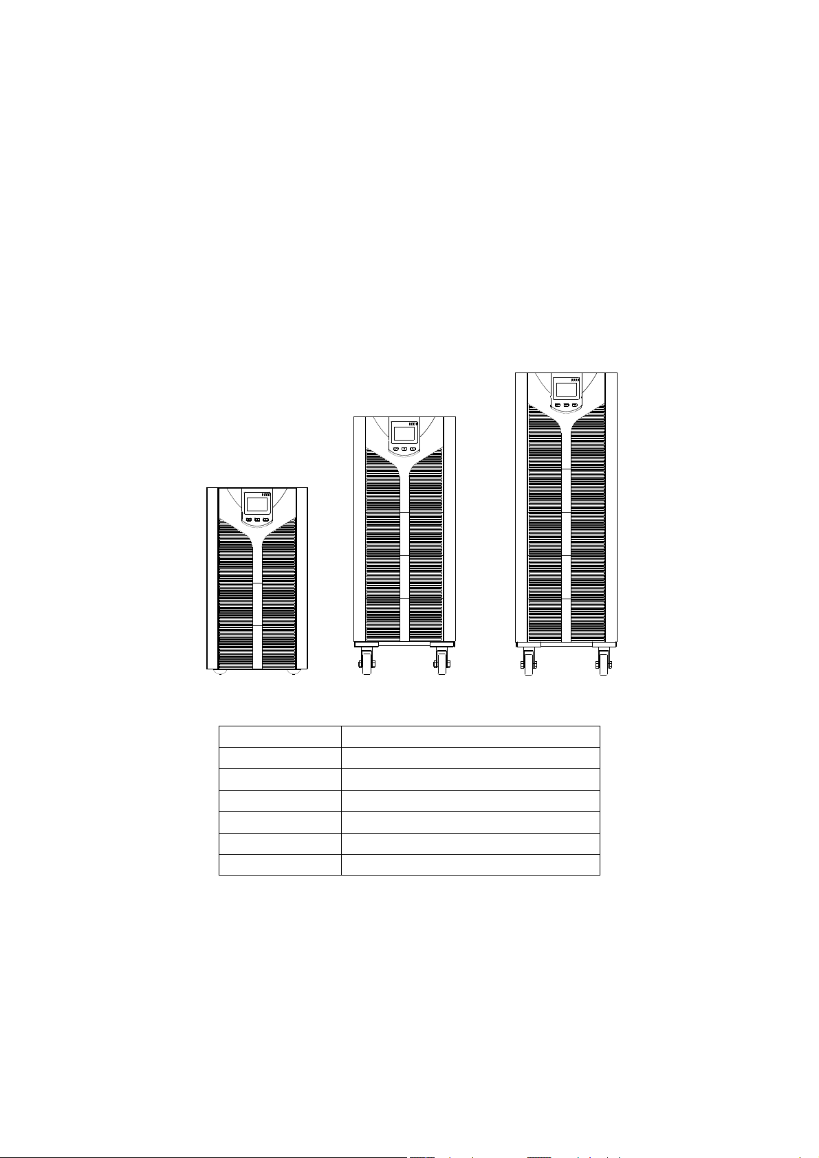
To determine whether this UPS is the model you want to buy. Check the model name showed
both on the front panel and rear panel of UPS to confirm.
Model Type
SE906S 6KVA Standard model
SE906H 6KVA Long backup model
SE9010S 10KVA Standard model
SE9010H 10KVA Long backup model
SE9015H 15KVA Long backup model
SE9020H 20KVA Long backup model
NOTE
Please save the packaging box and packaging materials for future transport use. As a heavy
product, please transit the UPS with care.
7
UDD-SD-112/ Release Date: 25.12.2014/Rev No: 1 /Rev. Date: 18.05.2015
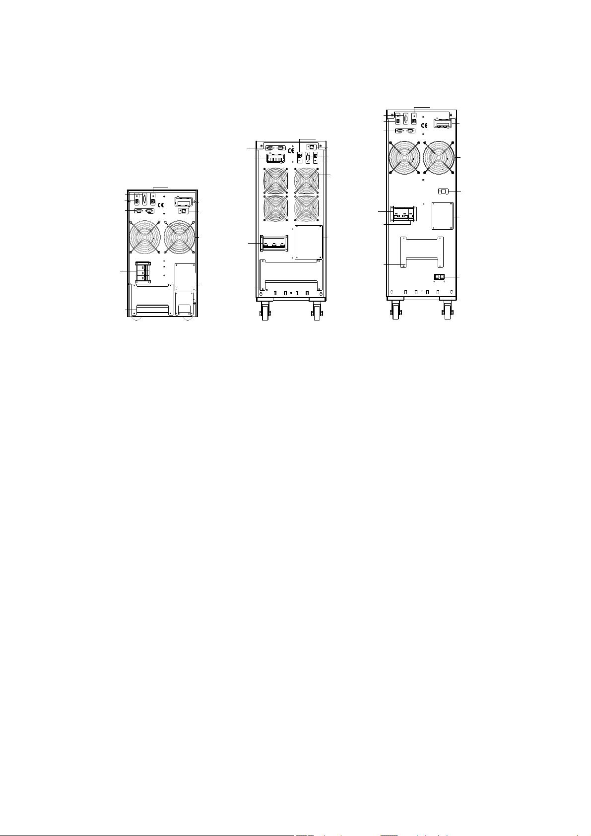
2.1 UPS Rear Panel View
USB
Parallel
Port
Intelligent
Slot
INTELLIGENT SLOT
RS232
USB
BAT_NTC
PARALLEL PORT
BAT_NTC
RS232
EPO
USB
RS232
EPO
Parallel
Port
EPO
EPO
RS232
PARALLEL PORT
Fan
USB
RS232
EPO
Parallel
Port
Input
Breaker
Terminal
Block
EPO
EPO
USB
USB
RS232
RS232
PARALLEL PORT
PARALLEL PORT
INPUT BREAKER
ON
OFF
WARNING
HIGH LEAKAGE CURREN T
EARTH CONNECTION ESSENTIAL
BEFORE CONNECTIN G SUPPLY
INTELLIGENT SLOT
INTELLIGENT SLOT
BAT_NTC
BAT_NTC
DO NOT OPEN EXCEPT
QUALIFIED TECHNICIAN
Intelligent
Slot
BAT_NTC
Fan
Manual
Bypass
Switch
Input
Breaker
Terminal
Block
INPUT BREAKER
ON
OFF
WARNING
HIGH LEAKAGE CURREN T
EARTH CONNECTION ESSENTIAL
BEFORE CONNECTIN G SUPPLY
DO NOT OPEN EXCEPT
QUALIFIED TECHNICIAN
Manual
Bypass
Switch
Input
Breaker
Battery
Breaker
Terminal
Block
INPUT
BATTERY
BREAKER
BREAKER
ON
a. 6KVA &10KVA Long back up b. 15KVA &20KVA Long back up c .6KVA & 10KVA Standard type
USB
ON
WARNING
HIGH LEAKAGE CURRENT
EARTH CONNECTION ESSENTIAL
BEFORE CONNECTING SUPPLY
INTELLIGENT SLOT
BAT_NTC
DO NOT OPEN EXCEPT
QUALIFIED TECHNICIAN
-+-+
EXT.BATTERY
Intellengent
Slot
Fan
BAT_NTC
Manual
Bypass
Switch
Ext.Battery
NOTE
Due to the technology upgrading and development, goods and diagrams might have some
differences.
UDD-SD-112/ Release Date: 25.12.2014/Rev No: 1 /Rev. Date: 18.05.2015
8

3 INSTALLATION INSTRUCTIONS
3.1 Attention items of Installation
1. The UPS installation environment must be with good ventilation, away from water,
flammable gases and corrosive entities.
2. Do not lie down the UPS against the wall so that front and side panel air intake hole, rear
panel air outtake hole will be unobstructed.
3. The peripheral environment temperature around the UPS should be within 0 ℃ ~ 40 ℃.
4. If dismantling the machine at low temperatures, there may be condensation droplets, users
can not install or operate it before UPS completely got dry both inside and outside,
otherwise there will be danger of electric shocks.
5. Place the UPS near the mains socket so that can cut off AC mains without any delay at any
emergent case.
6. Make sure the load connect to the UPS is off when users connect the load to UPS, and then
turn on the load one by one later.
7. Please connect the UPS with the socket which is over-current protected. Do not connect the
UPS with the socket which rated current is less than the Maximum input current of the UPS.
8. All the power socket should be configured with earthing device for safety.
9. UPS could be electrified or powered no matter the input power cable is tied or not, even
when the UPS is off. The only way to cut off the output is switching off the UPS and
disconnecting the mains power supply.
10. For all standard type UPS, it is advised to charge the battery over 8 hours before used. Once
the AC mains power energizes the UPS, it will automatically charge the battery. Without
prior charging, UPS output remains as usual but with shorter back-up time than normal.
11. When connected to motor, display equipment, laser printer etc, UPS power selection
should be based on the startup power of the load which is usually twice as rated power.
12. When wiring, please ensure input cables and output cables are connected firmly.
13. If install a leakage current protective switch, please install it on output cable.
14. For EA900II 6-20K Series UPS, before installing, prepare wires for terminal block of the
UPS based on the following tables.
Wiring spec
Model
Three-
phase
Input
6KVA S 6mm2 6 mm
6KVA H 6 mm2 6 mm
10KVA S 10 mm2 10 mm2 10 mm2 10 mm2 10 mm2 10 mm2
10KVA H 10 mm2 10 mm2 10 mm2 10 mm2 10 mm2 10 mm2
15KVA H 16 mm2 16 mm2 16 mm2 16 mm2 16 mm2 16 mm2
20KVA H 20 mm2 20 mm2 20 mm2 20 mm2 20 mm2 20 mm2
Single-
phase
Input
Output Battery
2
6 mm
2
6 mm
2
6 mm2 6 mm
2
6 mm2 6 mm
Non-
isolated
Neutral
2
2
Ground
6 mm
6 mm
2
2
UDD-SD-112/ Release Date: 25.12.2014/Rev No: 1 /Rev. Date: 18.05.2015
9
NOTE
When connecting, please make sure to connect input cables and output cables with terminals
firmly. When the input is three-phase, if the UPS is working on Bypass mode, the total current
goes through phase R, so the line widths of phase R must be the same as output. When the input
is single-phase, before doing input connection, users have to use two short wires to connect R&S
and S&T.
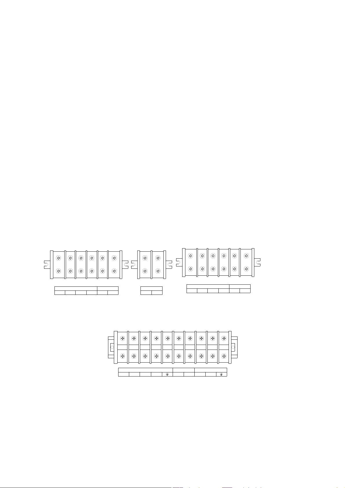
3.2 Output Connection
Output connection is configured with terminal blocks. Make sure the mains wire and breakers in
the building are enough for the rated capacity of UPS to avoid the hazards of electric shock or
fire.
NOTE
Do not use the wall receptacle as the input power source for the UPS, which rated current is less
than the UPS’s maximum input current. Otherwise the receptacle may be burned and destroyed.
INPUT
ABCN
OUTPUT
LN
BATTERY
++
INPUT
--
ABCN
OUTPUT
LN
a. 6KVA &10KVA Long back up terminal blocks b. 6KVA &10KVA Standard type terminal blocks
ABCNNL
c. 15KVA &20KVA terminal blocks
BATTERYINPUT
++--
OUTPUT
UDD-SD-112/ Release Date: 25.12.2014/Rev No: 1 /Rev. Date: 18.05.2015
10

3.3 Parallel System of 6-20K UPS Installation
Only 6-20K UPS and containing parallel ports can do parallel operation, other types is not
supported.
N+X parallel structure is the most reliable power supply structure at present, N stands for the
minimum number of UPS for the load, X stands for the number of redundant UPS,X absolutely
means how many UPS could be malfunctioning at the same time and the parallel UPS system is
still steady. The larger X is, the system is more reliable. N+X is the best method for high
reliability. Just install a little more simple accessories, at most 8 UPS could work together to form
a flexible parallel system.
This structure of power supply system increases the power safety and reliability. For example,
two single UPS make up a parallel system to load averagely, when one is malfunctioning, another
one can take all the load independently. It allows isolation repairs for malfunctioning UPS, and
according to users own different requirements, every single UPS could install manual
maintenance bypass switch.
3.3.1 Parallel System Installation
The function of parallel operation is an optional function of UPS, users can purchase parallel
function parts (including parallel card and parallel wire) and contact service personnel to install.
At most 8 UPS work together by using parallel wires to form a flexible parallel system. Each UPS
should be equipped individual battery pack.
>Parallel system installation requirement:
1. Install parallel wire, users need to purchase a specific parallel wire from our company, it’s not
recommended to use other type parallel wires. There are 2m length and 5m length to be
chosen.
2. Prepare wires for terminal block of the UPS based on the wiring spec table above in attention
items.
3. Each UPS input wiring please comply with the requirements of single UPS wiring.
4. Every UPS is recommended to connect together to one common utility power terminal block.
5. The output cables of each UPS are recommended to connect together on a common terminal
block, then output to the load.
6. Each UPS should be equipped individual battery pack.
7. Wiring installation for parallel UPS system please refer to the wiring diagrams are given
below, switches of 6KVA should withstand more than 50A/250VAC, and switches of 10KVA
should withstand more than 80A/250VAC, and switches of 15KVA should withstand more
than 100A/250VAC, and switches of 20KVA should withstand more than125A/250VAC.
8. Output wiring length requirements: when the distance between the load and each UPS is less
than 20 meters, the length difference of cables to the load should be less than 20%; when the
distance between the load and each UPS is more than 20 meters, the length difference of
cables to the load should be less than 10%.
11
UDD-SD-112/ Release Date: 25.12.2014/Rev No: 1 /Rev. Date: 18.05.2015
>Installation procedure:
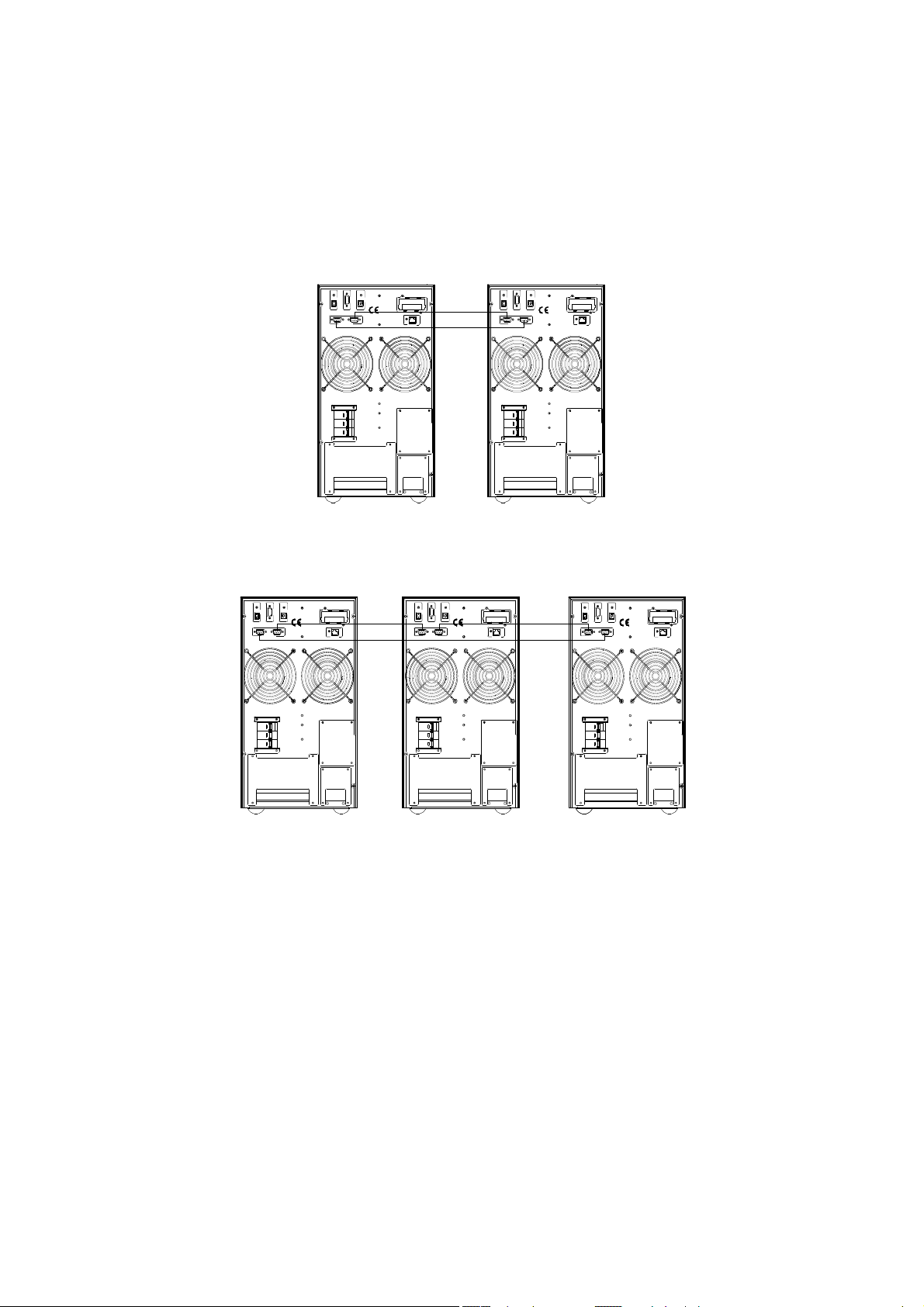
① Install parallel wires. Two UPS to form an UPS parallel system, in order to ensure the
reliability of the parallel system, there is only one way to wire two UPS, use two parallel wires to
connect two UPS like the diagram showing below, connection looks like a circle. If three or more
than three UPS are needed, the connection is similar, you can refer to the diagram as below. How
many UPS unit, how many parallel wires you need.
INTELLIGENT SLOT
EPO
EPO
RS232
RS232
PARALLEL PORT
PARALLEL PORT
INTELLIGENT SLOT
USB
USB
BAT_NTC
BAT_NTC
EPO
EPO
PARALLEL PORT
PARALLEL PORT
RS232
RS232
INTELLIGENT SLOT
INTELLIGENT SLOT
USB
USB
BAT_NTC
BAT_NTC
INPUT BREAKER
ON
OFF
ON
WARNING
HIGH LEAKAGE CURRENT
EARTH CONNECTION ESSENTIAL
BEFORE CONNECTING SUPPLY
DO NOT OPEN EXCEPT
QUALIFIED TECHNICIAN
INPUT BREAKER
ON
OFF
ON
WARNING
HIGH LEAKAGE CURRENT
EARTH CONNECTION ESSENTI AL
BEFORE CONNECTING SUPPLY
DO NOT OPEN EXCEPT
QUALIFIED TECHNICIAN
Parallel system of two UPS wiring
INTELLIGENT SLOT
USB
USB
WARNING
HIGH LEAKAGE CURRENT
EARTH CONNECTION ESSENTIAL
BEFORE CONNECTING SUPPLY
INTELLIGENT SLOT
BAT_NTC
BAT_NTC
DO NOT OPEN EXCEPT
QUALIFIED TECHNICIAN
EPO
EPO
RS232
RS232
PARALLEL PORT
PARALLEL PORT
INPUT BREAKER
ON
OFF
EPO
EPO
RS232
RS232
PARALLEL PORT
PARALLEL PORT
INPUT BREAKER
ON
OFF
USB
USB
WARNING
HIGH LEAKAGE CURRENT
EARTH CONNECTION ESSENTIAL
BEFORE CONNECTING SUPPLY
INTELLIGENT SLOT
INTELLIGENT SLOT
BAT_NTC
BAT_NTC
DO NOT OPEN EXCEPT
QUALIFIED TECHNICIAN
INTELLIGENT SLOT
USB
USB
WARNING
HIGH LEAKAGE CURRENT
HIGH LEAKAGE CURRENT
EARTH CONNECTION ESSENTIAL
EARTH CONNECTION ESSENTIAL
BEFORE CONNECTING SUPPLY
BEFORE CONNECTING SUPPLY
INTELLIGENT SLOT
BAT_NTC
BAT_NTC
DO NOT OPEN EXCEPT
QUALIFIED TECHNICIAN
EPO
EPO
RS232
RS232
PARALLEL PORT
PARALLEL PORT
INPUT BREAKER
ON
OFF
Parallel system of three UPS wiring
Caution
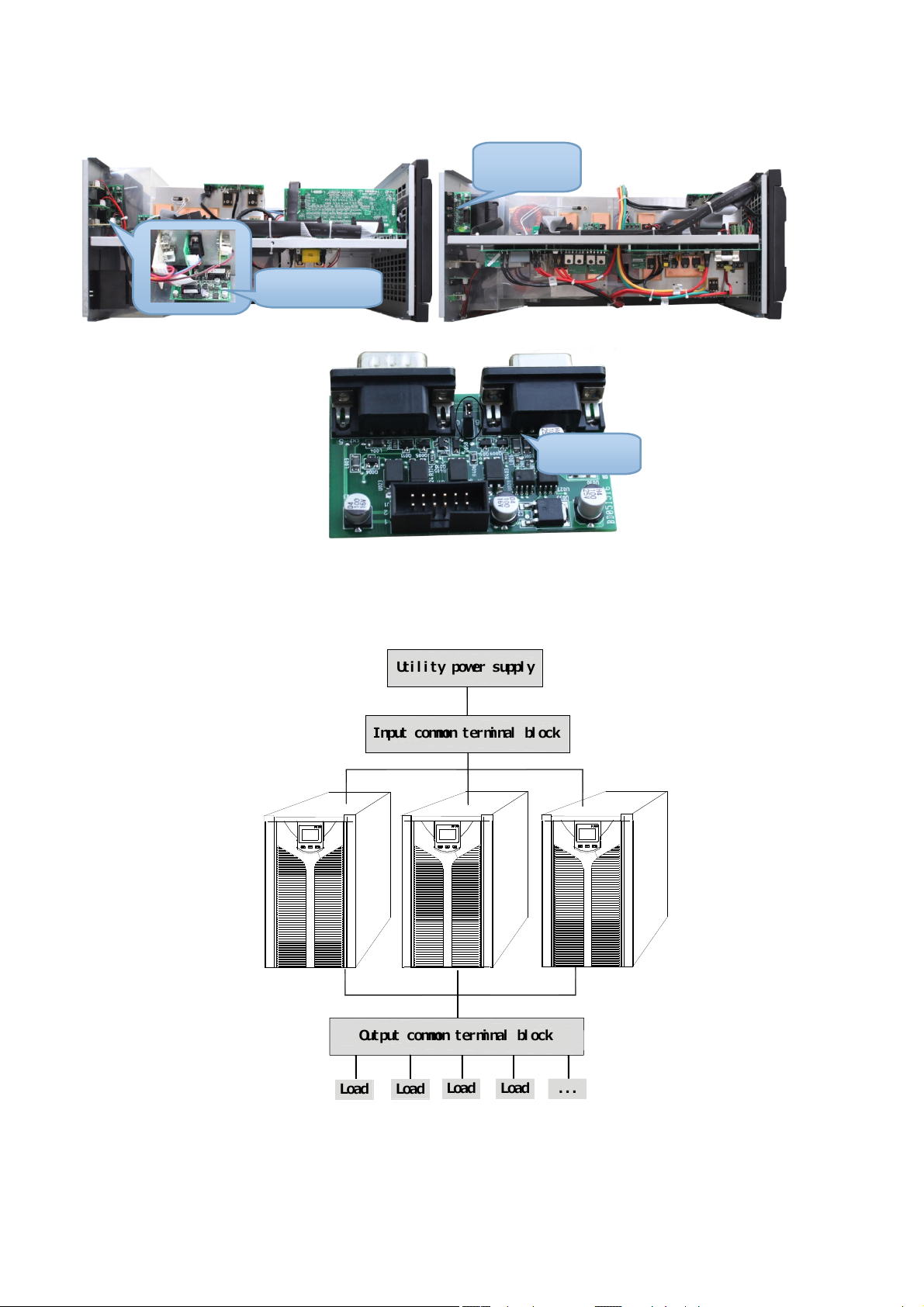
For three UPS parallel system or more than three unites system type, please remove the short
pin CN3 on the parallel card as following pictures, Only keep the first unit and the last unit shot
pin(CN3) connected and remove the rest ones. Open the UPS cover, find the parallel card, it’s
installed on the rear panel. Take off the short pin CN3, then screw the cover back. It’s advisable
to contact to local dealer to operate, if you have to operate by yourself, please be sure that you
have cut off all the electrical connection, be careful the electric shocks from the UPS inside.
UDD-SD-112/ Release Date: 25.12.2014/Rev No: 1 /Rev. Date: 18.05.2015
12
Parallel
Parallel Card
6KVA &10KVA Parallel Card 15KVA &20KVA Parallel Card
Short Pin
②Connect output cables of all UPS together to a common terminal block.
③Connect input cables of all UPS together to one common utility power terminal block.
Utility power suppl
Input common terminal block
y
Output common terminal bloc
Loa
Loa
Loa
d
d
Parallel UPS system view
d
Loa
k
...
d
UDD-SD-112/ Release Date: 25.12.2014/Rev No: 1 /Rev. Date: 18.05.2015
13
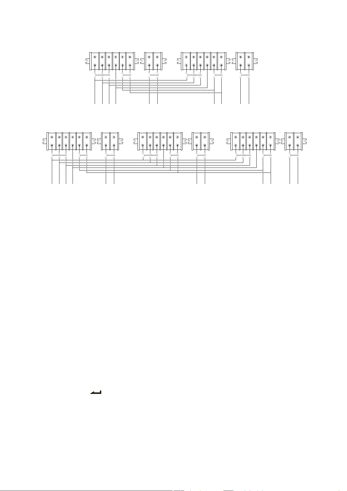
RS
INPUT
TNL
BAT+ BAT-
N
BAT1
RS
TNL
OUTPUT
BAT+ BAT-
N
BAT2
Wiring diagram for two UPS parallel system
RS
TNL
BAT+ BAT-
N
INPUT BAT1
RS
TNL
BAT+ BAT-
N
BAT2
Wiring diagram for thee UPS parallel system
RS
TNL
OUTPUT
BAT+ BAT-
N
BAT3
④ If the UPS is the standard type, each UPS has batteries inside already. If the UPS is the longrun type, each UPS should be equipped a individual battery pack.
⑤ After installation, check all the wiring carefully, be sure to conirm correct, then can operate
the system.
3.3.2 Parallel System Operation and Maintenance
General operation of parallel system, please refer to the operation instruction of single UPS.
Before starting the system, need to set up different ID for each UPS, specific settings please refer
to the instruction of ID setting which is given in single UPS panel function setting.
>Turn on the parallel system
Start the system with mains power: After inputting the mains power,turn on any one UPS of
system, others will start by themself at same time. All UPS will enter into Line mode.
Start the system without mains power: Make sure the battery pack is connected well and the
breaker is in “ON” position. There are two ways to start the UPS parallel system without utility
power supply:
A: Press the key on each UPS, make each LCD of each UPS light up, then turn on any one
UPS of system, others will start by themself at same time. All UPS will enter into BAT mode.
B: Turn on UPS one by one.
UDD-SD-112/ Release Date: 25.12.2014/Rev No: 1 /Rev. Date: 18.05.2015
14
 Loading...