

Page 1

USER MANUAL
POWERPACK PRIME SERIES
1 - 3 KVA
Page 2

UDD-SD-113/ Release Date: 26.12.2014/Rev No: 0/Rev. Date:
1
Page 3

UDD-SD-113/ Release Date: 26.12.2014/Rev No: 0/Rev. Date:
2
USER MANUAL
POWERPACK PRIME SERIES
1 - 3 KVA
UDD-SD-113
About The Manual
This manual is prepared for the users of Powerpack Prime Series 1-3 kVA.
Companion Manuals
For further information about this device and its options, please visit www.makelsan.com.tr
Updates
Please visit www.makelsan.com.tr for updates. Always use the latest manuals.
Page 4

POWERPACK PRIME SERIES 1-3 kVA CONTENTS
UDD-SD-113/ Release Date: 26.12.2014/Rev No: 0/Rev. Date:
3
CONTENTS
1 PRODUCT INTRODUCTION ........................................................................................................................................ 5
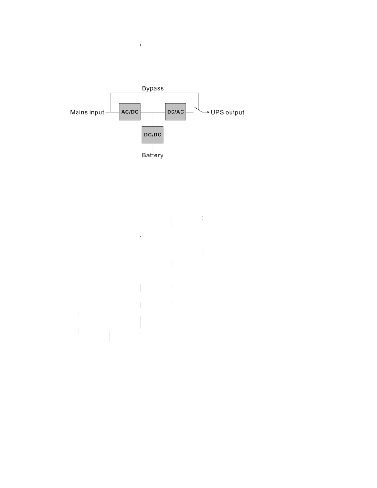
1.1 Function description ............................................................................................................................................. 5
1.2 Front Panel ................................................................................................................................................................ 6
1.2.1 Front View ............................................................................................................................................................. 6
1.2.2 LCD and LED Display ......................................................................................................................................... 6
1.2.3 Button ...................................................................................................................................................................... 7
1.3 Rear panel ................................................................................................................................................................. 8
1.4 Mode description .................................................................................................................................................... 9
1.5 Product Specification ......................................................................................................................................... 11
1.5.1 Model description ........................................................................................................................................... 11
1.5.2 Environment Specification ......................................................................................................................... 12
1.5.3 Mechanical Specification ............................................................................................................................. 12
1.5.4 Electrical Specification ................................................................................................................................. 13
1.6 Communication Port ......................................................................................................................................... 14
1.6.1 RS232................................................................................................................................................................... 14
1.6.2 Intelligent Card ................................................................................................................................................ 14
2 INSTALLATION ............................................................................................................................................................. 15
2.1 Safety Instructions for Installation .............................................................................................................. 15
2.2 Unpacking and Inspection ............................................................................................................................... 16
2.3 Installation Steps for Standard Model ........................................................................................................ 16
2.4 Installation for Communication Software (Optional) .......................................................................... 16
3 OPERATION ...................................................
................................................................................................................ 17
3.1 Operation Safety Instructions ........................................................................................................................ 17
3.2 Start the UPS with mains (AC source) ........................................................................................................ 18
3.3 Start the UPS with battery (DC source) only............................................................................................ 18
3.4 Connect loads to UPS ......................................................................................................................................... 19
3.5 Charge the batteries ........................................................................................................................................... 20
3.6 Discharge the batteries ..................................................................................................................................... 20
3.7 Test the batteries ................................................................................................................................................. 20
3.8 Turn off the UPS with mains (AC source) .................................................................................................. 20
3.9 Turn off the UPS with battery (DC) only .................................................................................................... 21
Page 5

POWERPACK PRIME SERIES 1-3 kVA CONTENTS
UDD-SD-113/ Release Date: 26.12.2014/Rev No: 0/Rev. Date:
4
4 MAINTENANCE ............................................................................................................................................................ 22
4.1 Maintenance Safety Instructions .................................................................................................................. 22
4.2 Typical Troubleshooting .................................................................................................................................. 24
4.3 Battery Maintenance .......................................................................................................................................... 25
4.4 Contact the service centre ............................................................................................................................... 26
5 TRAMSPORT and STORAGE .................................................................................................................................... 26
6 STANDARDS .................................................................................................................................................................. 26
7 GUARANTEE .................................................................................................................................................................. 27
7.1 Terms of Guarantee ............................................................................................................................................ 27
7.2 Cases Not Covered by the Guarantee .......................................................................................................... 28
8 CONTACT INFORMATION ........................................................................................................................................ 32
Page 6
POWE
R
1 P
R
1.1 Fu
n
This
prov
all
m
mai
n
outp
u
Whe
n
DC/
D
Afte
r
wor
k
the
U
The
U
dire
c
The
U
the
m
PACK PRIM
ODU
C
ction des
product is
ides perfec
t
ains power
s voltage, s
u
t voltage c
a
the main
s
C section i
m
the mains
s again. So
PS is turne
d
PS also pr
o
tly when th
PS is equi
p
ains are w
i
E SERIES 1
-
T IN
T
cription
a true on
l
protection
disturbanc
o it is a hig
h
n be a pur
e
input bec
o
mediatel
y
input come
the load is
on.
vides an in
t
e UPS is off
ped with
a
thin a reas
o
3 kVA
ROD
U
ine double
for critical
es. The inp
u
power fa
c
& stable si
me abnor
m
to make s
u
back to no
r
always po
w
ernal bypa
s
or failed.
n internal
c
nable rang
e
CTIO
N
-conversio
n
load such a
t AC curre
n
tor system.
ne wave A
C
al, the co
n
re the DC/
A
mal range,
er-supplie
d
s path so t
h
harger for
b
under “by
p
UPS (Uni
n
s computer
t can be co
Through t
h
voltage.
troller wil
l
C (inverte
r
the DC/DC
through i
n
at the load
atteries w
h
ass mode”
terruptibl
e
system. It
c
rrected to
a
e PWM co
n
stop the
A
) section c
a
will be sto
p
verter wit
h
can be po
w
ich charge
s
or “line mo
d
Power S
u
an elimina
t
wave follo
w
trol techno
C/DC and
s
n continue
ped and t
h
out any in
t
ered by ma
i
the batter
i
e”.
5
pply). It
e almost
ing the
logy, the
tart the
to work.
e AC/DC
errupt if
ns input
es when
Page 7
POWERPACK PRIME SERIES 1-3 kVA
6
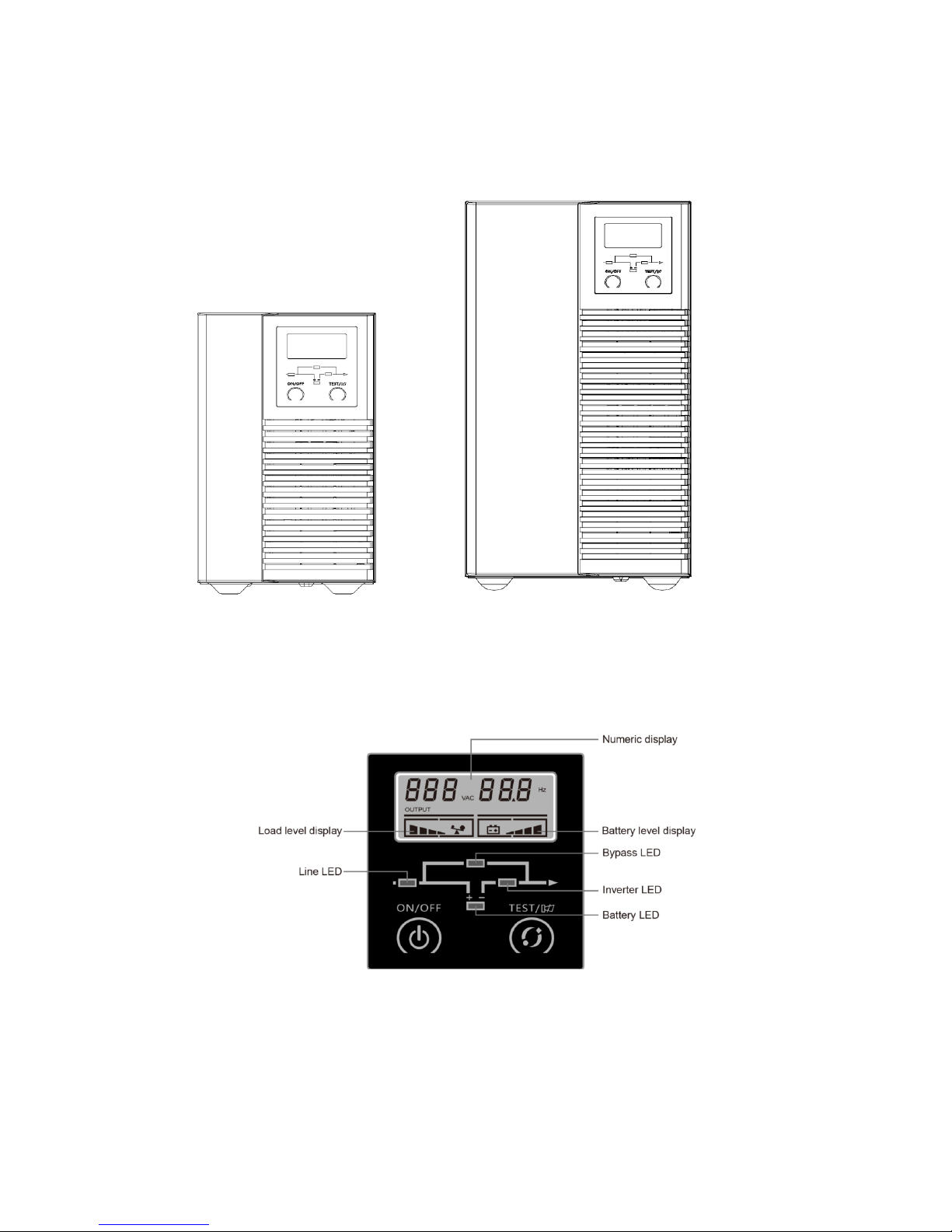
1.2 Front Panel
1.2.1 Front View
1K 2K/3K
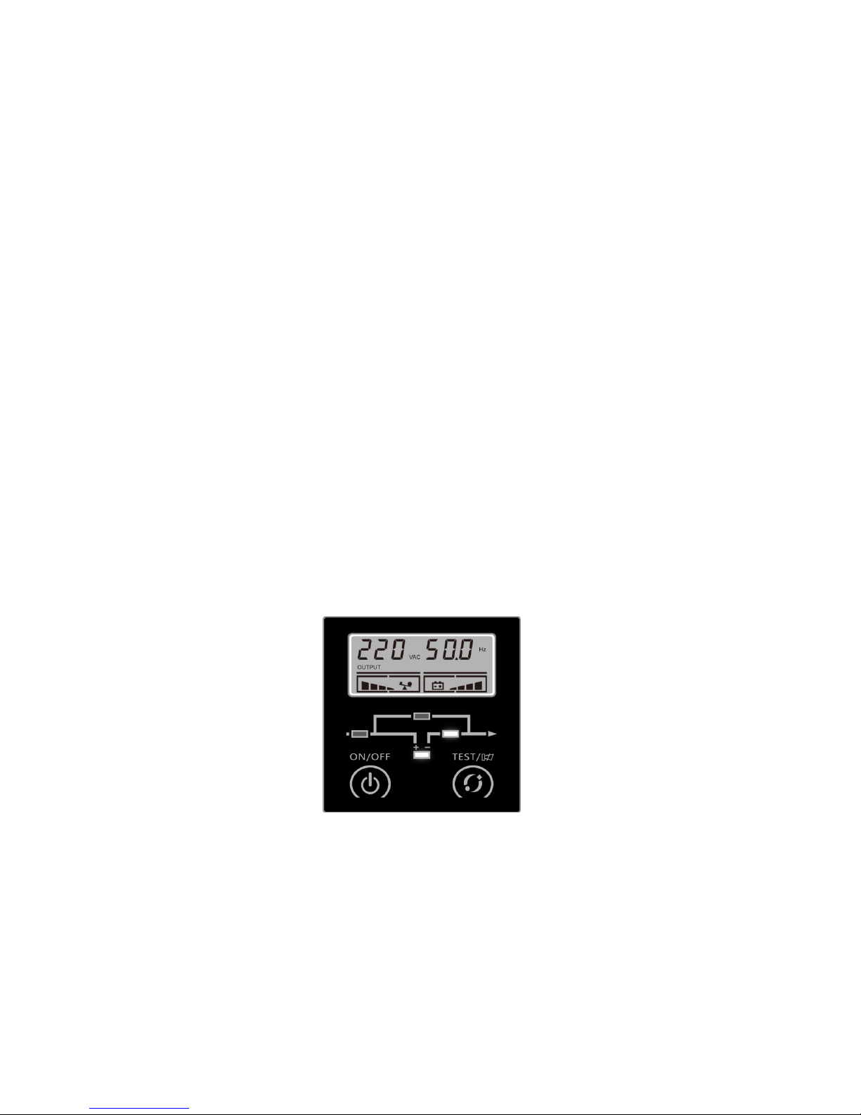
1.2.2 LCD and LED Display
Page 8

POWERPACK PRIME SERIES 1-3 kVA
7
LED definition
There are total 4 LEDs to indicate the status of UPS.
Name Colour Function
Bypass LED
Orange
To indicate that the UPS is in bypass mode, and the load
current is directly from the mains power.
Line LED Green To indicate that the mains input is normal.
Inverter LED Green
To indicate that the load current is supplied from the mains
power or battery via the inverter.
Battery LED Orange
To indicate that the UPS is in battery mode, and the load
current is from battery via the inverter.
1.2.3 Button
(1) ON/OFF button
Turn on UPS
Press ON/OFF button for 1 second to turn on UPS. UPS would send a
beep to indicate the power-on status
Turn off UPS
Press ON/OFF button for 1 second to turn off UPS when UPS is in line
mode or battery mode.
Clear fault status Press ON/OFF button for 3 seconds to clear the fault status of UPS.
(2) Test button
Battery test In line mode, press test button for 2 seconds to test the battery.
Mute in battery
mode
Press test button for 2 seconds in battery mode, UPS would be muted.
To resume the alarm, press test button again for 2 seconds.
Mute in all mode
Press test button for 10 seconds, UPS would be muted. To resume the
alarm, press test button again for 10 seconds. The key tone and
battery voltage under alarm (every second buzzer beep twice) cannot
be muted.
Page up/down
Press test button for 0.5 seconds, UPS would turn from main menu to
sub-menu in sequence
Page 9
POWERPACK PRIME SERIES 1-3 kVA
8
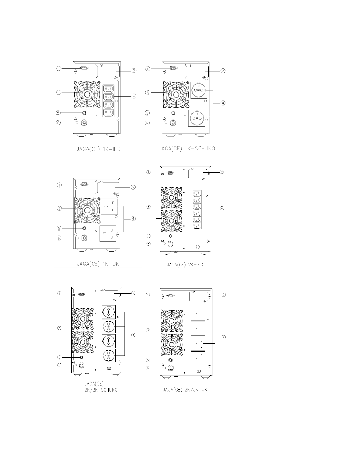
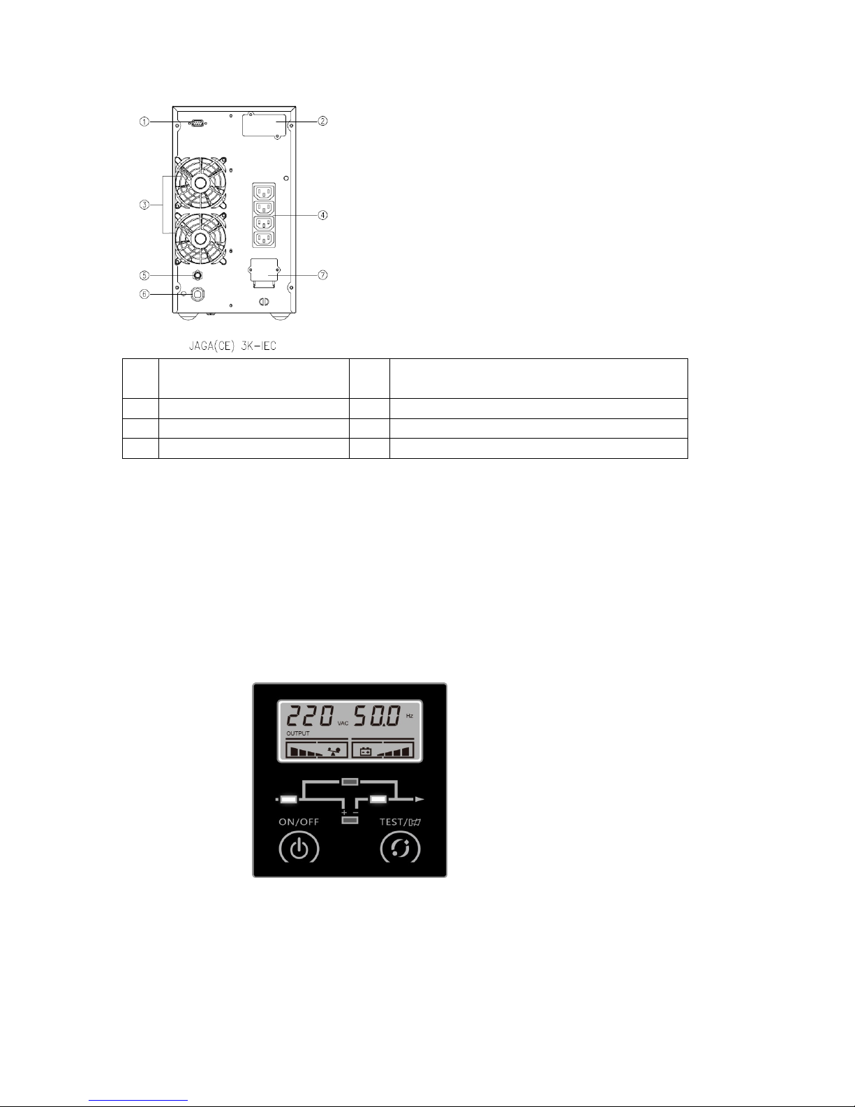
1.3 Rear panel
Page 10
POWERPACK PRIME SERIES 1-3 kVA
9
1 Communication port
(RS232)
5 Mains input protection
2 Intelligent card slot 6 Mains input power cord
3 Fan 7 Output terminal block
4 Output socket
1.4 Mode description
Line mode
Line mode means that the mains input is rectified/converted by the AC/DC section and then inverted
to stable output by DC/AC section. In line mode, the output is well-regulated and good to the loads. If
the mains get abnormal, the UPS will transfer to battery mode without interruption.
In line mode, Line LED and Inverter LED are turned on constantly.
Line mode
Page 11
POWERPACK PRIME SERIES 1-3 kVA
10
1. If Line LED flashes, it means that the input may have something wrong, such as input L and N
line reversed or the grounding wire is not connected properly.
2. If the load level is higher than 100%, the buzzer will beep once every 0.5 second as a warning
for the over-loading condition. The user should remove unnecessary loads one by one, until
the load level become lower than 100%.
3. If the Battery LED flashes, it means that the battery is not connected or the battery level is too
low. In this case please check the connection of battery and press test button for 2 seconds to
test the battery. If the connection is normal, it’s possible the battery is failed or aged. Please
refer to the common troubleshooting table in chapter
Connecting AC Generator as Input
Remove the loads connected to UPS first. Activate the generator and connect the output of
generator with the input of UPS until the generator operates stably, then turn on the UPS and
add the loads one by one.
Please choose the generator with output capacity which is twice larger than the UPS capacity.
Battery mode
Battery mode means that the battery power goes through the DC/DC section to the inverter
(DC/AC) and output a stable backup power when the mains are failed. If the mains recovered,
the UPS will transfer to line mode without interruption.
In battery mode, Battery LED and Inverter LED are turned on constantly. If Line LED flashes at
the same time, it means that the input mains are abnormal.
1. In battery mode, Buzzer beeps once every 4 seconds. Press test button for 2 seconds in battery
mode, UPS would be muted. To resume the alarm, press test button again for 2 seconds.
2. When the voltage of battery decline to the lower limit, buzzer beeps once every second to
warn the low battery status and remind user to turn off the loads.
3. User may check the backup function by turning on the UPS without connecting the mains
input.
Battery mode
Page 12

POWE
R
Byp
a
Bypass
directly
output
(on/off
)
In bypa
s
minute
s
1. If Li
n
N lin
2. The
d
3. UPS’
s
1.5 Pr
o
1.5.1
M
Thi
s
M
oPow
PACK PRIM
ss mode
mode mea
n
without an
y
to protect
could be s
e
s mode, Li
n
.
e LED flas
h
e reversed
o
escription
backup fu
n
duct Spe
c
odel des
c
manual is
a
del name
er rating
E SERIES 1
-
s that the
U
regulatio
n
the load.
T
t by softwa
e LED and
es, it mean
s
r the grou
n
of other LE
D
ction is no
t
ification
ription
pplicable t
o
1K
1000VA/8
B
3 kVA
PS provid
e
. If the cont
he bypass
re tool.
Bypass LE
D
that the i
n
ding wire i
s
s is the sa
m
enabled u
n
the follo
w
00W 2000
V
ypass mo
d
s the powe
roller detec
t
voltage/fr
e
are turne
d
put may h
a
not conne
c
e as line
m
der bypass
ing models
:
2K
A/1600W
e
r through t
h
s the main
s
quency ra
n
on consta
n
ve somethi
n
ed proper
l
ode.
mode.
3K
3000VA/2
4
e internal
is abnorm
a
ge and d
e
tly. Buzze
r
g wrong, s
u
.
00W
bypass pat
h
l, it will sh
u
fault outp
u
beeps onc
e
ch as inpu
t
11
to load
t off the
t status
every 2
L and
Page 13

POWERPACK PRIME SERIES 1-3 kVA
12
1.5.2 Environment Specification
Model 1K 2K 3K
Operating
Te mp er at ur e
0-40°C
Storage
Temperature
-25-55°C
Altitude
<1000m @ full load
<2000m @ 91%load
<3000m @ 82%load
<4000m @ 74%load
Relative Humidity
20%-90%
Noise Level
<45dB @ 1
meter from
front panel
<50dB @ 1 meter from front
panel
1.5.3 Mechanical Specification
Model 1K 2K 3K
Dimension
(W×H×D)
(mm)
144×229×345 190×328×393 190×328×393
Weight
(Kg)
9.2
17.2
22.6
Page 14

POWERPACK PRIME SERIES 1-3 kVA
13
1.5.4 Electrical Specification
Model 1K 2K 3K
Power
1000VA/800W
2000VA/1600W 3000VA/2400
W
Input
Current (Max.) 5A 10A 14.3A
Voltage Range 80VAC-285VAC(Default 180-264VAC)
Frequency Range 40-70Hz
Input Power
Factor
≧0.98 @ full load
Output
Voltage
200*/208*/220/230/240VAC (sine-wave)
Frequency
Synchronizing mains input @ line mode
50/60Hz ± 0.05 Hz @ battery mode
Voltage
Regulation
± 2%
Overload Capacity
47s~25s linear @ 105%~150%; 25s~300ms
linear @150%~200%; >200% : 200ms
Efficiency
Line Mode 89% 90% 90%
Battery Mode 83% 83% 83%
Battery & Charger @ 25C
Total battery
rating voltage
24Vdc 48Vdc 72Vdc
Backup Time (Full
Load)
>4.5min >4.5min >4.5min
Recharge Time (to
90%)
<7Hours <7Hours <7Hours
Charging Curren
t
(Max.)
1A 1A 1A
Discharging
Current (Max.)
53A 53A 53A
Rated Charging
Voltage
27Vdc-
27.6Vdc
54Vdc-
55.2Vdc
81Vdc-
82.2Vdc
*: If the rating output voltage is 200/208VAC, the rating power
will be decreased to 90%.
*. Can’t support half wave load.
Page 15

POWERPACK PRIME SERIES 1-3 kVA
14
1.6 Communication Port
1.6.1 RS232
The communication port (RS232) is for the connection with PC which is installed with
monitoring software.
Pin assignment of the DB-9 connector is shown below:
Pin# Definition
2 TXD (output)
3 RXD (input)
5 GND
1.6.2 Intelligent Card
Intelligent card - AS400 card, NMC card and CMC card are optional. The intelligent card is
inserted into intelligent card slot.
a- AS400 card: Monitor the UPS by using the AS400 management function if the system has
AS400 interface.
b- NMC card: Communication with the PC via internet for remote monitoring and control of
the UPS.
c- CMC card: a centralized-control card for remote monitoring
NOTE
Please contact with distributor or service center for detail information about intelligent
cards.
Page 16

POWE
R
2 IN
2.1 Sa
fe
Inst
a
Inst
a
D
UPS is
m
before
b
Otherw
i
D
sunligh
t
D
with go
o
Wiri
I
n
and reg
u
T
make s
u
D
A
should
b
T
h
p
e
Pleas
PACK PRIM
STAL
L
ty Instru
llation Pe
r
llation En
v
o not insta
l
oved sudd
e
eing instal
se hazard
o
o not insta
l
or heat. E
n
o not bloc
k
d ventilati
o
ng & Grou
n
stallation
a
lations.
he UPS m
u
re the batt
e
o not conn
e
n approp
r
e provided
is product
rsonnel ac
c
e read the
f
E SERIES 1
-
ATIO
N
ctions for
sonnel
ironment
l and oper
a
nly from a
led and op
e
f electric s
h
l the UPS i
n
sure the U
P
the air ve
n
n. Ensure
e
ding
nd Wiring
st be secu
r
ry cabinet
s
ct Input N
w
iate switch
in the inpu
t
must be in
s
ord to safe
t
ollowing s
3 kVA
Installati
o
te the UPS
cold enviro
rated. Ple
a
ock may ex
i
the enviro
n
S is far awa
ts on the h
o
nough spa
c
must be p
e
ely ground
have the e
q
ire and ou
t
device as
mains.
talled only
y instructi
o
afety instr
u
n
if there is
w
nment to a
se allow a
n
st!
ment whe
r
y from wat
e
using of U
P
e on each s
i
rformed i
n
ed. If there
uipotentia
l
put N wire
backup pr
o
by qualifie
ns!
ctions be
f
ater cond
e
arm one.
T
acclimati
z
e it is dam
p
r, inflamm
a
S. The UP
S
de for vent
i
accordanc
are extern
a
earth bon
d
together.
tection fo
r
d or profes
ore install
a
nsation wh
he UPS m
u
ation time
or would
b
ble gas an
d
must be i
n
lation.
e with the
l UPS batt
ing to the
U
over-curr
e
sional
tion!
ich may oc
c
st be absol
u
of at least
e exposed
corrosive
a
stalled in a
local electr
i
ery cabinet
PS main ca
b
ent or sho
r
15
ur if the
tely dry
2 hours.
to direct
gents.
location
cal laws
s, please
inet.
-circuit
Page 17

POWE
R
B S
packs i
n
D
and the
2.2
Un
p
1. Unp
a
2. Insp
e
turn on
2.3 Ins
t
1. Mak
e
avoi
d
2. Mak
e
3. Mak
e
4. Turn
5. Mak
e
6. Con
n
7. Con
n
2.4 Ins
t
1. Con
n
2. Plea
s
oper
a
PACK PRIM
attery
trictly follo
w
parallel.
C breaker
o
UPS. The s
p
acking a
n
ck the pac
k
1 UPS
1 user man
u
ct the app
e
the unit an
d
allation St
e
sure the
w
the hazar
d
sure the
m
sure the U
off all loads
sure the p
r
ect the loa
d
ect the inp
u
allation fo
r
ect the co
m
e refer to t
h
tion of ma
n
E SERIES 1
-
the prin
c
r fuse mus
t
ecification
o
d Inspect
i
age and ch
e
al
arance of t
h
notify the
ps for Sta
n
ire / circ
u
s of electri
c
ains switc
h
PS is not tu
r
firstly befo
r
otective ea
s to the UP
S
t power co
r
Commun
i
municatio
n
e guide m
a
agement (
m
3 kVA
iple of “sa
m
be used as
f protectio
on
ck the cont
e UPS to s
e
dealer imm
dard Mod
e
it breaker
shock and
in the buil
d
ned on bef
o
e connectin
g
rth ground
through t
h
d of UPS t
o
cation Sof
t
cable bet
w
nual of sof
t
onitoring
)
e voltage,
s
a protectio
n
ns must m
a
ents. The s
h
e if there i
s
ediately if t
h
l
/ socket ar
fire.
ing is swit
c
re wiring
o
to the UPS
.
is correctly
e outlet so
c
mains.
ware (Opt
i
een UPS an
d
ware or co
n
software.
ame type”
device be
t
tch the UPS
ipped pack
a
any dama
g
ere is any
d
e enough f
o
hed off.
peration.
connected.
kets.
onal)
PC.
tact the se
r
when conn
ween the e
x
’s specifica
t
ge contain
s
e during tr
a
amage or l
a
r the curr
e
vice cente
r
ecting mult
ternal bat
t
ion.
:
nsportatio
n
ck of som
e
nt rating
o
for install
a
16
i battery
ery pack
. Do not
parts.
f UPS to
tion and
Page 18

POWE
R
3 O
P
3.1 Op
e
Ope
r
Ope
r D
Pleas
e
T
h
PACK PRIM
ERA
T
ration S
a
ation pers
ation war
n
o not disc
o
at any tim
e
connected
l
Do not tr
disconnect
i
The UPS o
u
to the main
Make sure
Turn off t
h
electric sh
o
read the
f
e product i
E SERIES 1
-
ION
fety Instr
u
onnel
ing
nnect the
e
since this
oads.
y to disas
s
ng it from t
h
tput socke
t
s power so
u
no liquid o
r
e mains in
p
ck or fire
c
ollowing s
s designed
t
3 kVA
ctions
arth wire
o
would res
u
emble the
e mains p
o
may be el
e
rce.
foreign obj
ut switch a
losed to th
e
afety instr
u
o be opera
n the UPS
o
lt in the v
o
original
p
wer & exte
r
ctrically liv
e
ects enter t
h
nd external
UPS.
ctions be
f
ted by gen
e
r the wiri
n
id of prot
e
art of the
nal batter
y
d even if t
h
e UPS.
battery sw
i
ore operat
i
ral users.
g terminal
s
ctive earth
UPS befo
r
.
e UPS syst
e
tch immed
i
on!
of ground
i
for the UP
S
e turning
m is not c
o
ately in the
17
ng point
and all
off and
nnected
event of
Page 19

POWERPACK PRIME SERIES 1-3 kVA
18
3.2 Start the UPS with mains (AC source)
1. Press the on/off button of the UPS front panel continuously for more than 1 second. The
buzzer will beep once, the numeric area of LCD display will be lighted in sequence, after a few
seconds of self-diagnosis, the UPS will be turned on in normal mode (line mode) and feed the
output power with constant AC voltage, if the mains abnormal, UPS will shift into battery
mode after self-diagnosis.
2. When the UPS enters line mode normally, the Inverter LED will be on, the Bypass LED and
Battery LED will be off. There will be no beep from buzzer.
3. Press the battery test button for 0.5 second, UPS will show the information on LCD display as
followings in a circular order.
3.3 Start the UPS with battery (DC source) only
1. This UPS can be started directly with DC source (battery), without AC source.
2. Press the on/off button of the UPS front panel continuously for more than 1 second. The
buzzer will beep once, the numeric area of LCD display will be lighted in sequence, after a few
seconds of self-diagnosis, the UPS will be turned to the battery mode and feed the output
power with constant AC voltage.
Page 20

POWERPACK PRIME SERIES 1-3 kVA
19
3. When the UPS enters battery mode normally, the Inverter LED, and Battery LED will be on,
the Bypass LED will off.
4. Press the battery test button for 0.5 second, UPS will show the information on LCD display as
followings in a circular order.
5. To remind, UPS is under battery mode, it would send out beep once per 4 seconds, and user can
enable/disable the buzzer by pressing battery test button for 2 seconds.
Note: If the UPS shuts down in battery mode automatically, it will resume to line mode
automatically when the mains power is recovered.
3.4 Connect loads to UPS
After turning the UPS on, the loads can be switched on, and it is recommended to switch on the
loads one by one.
1. If it is necessary to connect the inductive load such as a printer to the UPS, the start-up power
should be considered for determining the capacity of the UPS because the power
consumption for inductive load during start-up could be large.
2. If the UPS is overloaded, the buzzer will beep twice every second as warning.
3. If the UPS is overloaded, some loads must be switched off or decreased immediately. It is
recommended that the total loads connected to the UPS be less than 80% of UPS’s nominal
output power rating to prevent the overloading during transient time and make the system
more satiable.
4. If the overloading time is too long in line mode, the UPS will transfer to bypass mode. After
the overloading disappeared, it will return to line mode. If the overloading time is too long in
battery mode, the UPS will cut off the output and then shutdown according battery level
Page 21

POWERPACK PRIME SERIES 1-3 kVA
20
3.5 Charge the batteries
1. When the UPS is connected to normal mains, the charger will start to work and charge the
batteries automatically.
2. It is suggested to charge the batteries for 10 hours at least before the UPS performs battery
mode. Otherwise the backup time may be less than the expected value.
3.6 Discharge the batteries
1. When the UPS is in battery mode, the buzzer will start beep according to different battery
level. If the battery voltage drops to the alarming level, the buzzer will start beep rapidly
(once every sec) to remind the user that the capacity of battery is too low and the UPS will be
shutdown automatically soon. The user may switch off some non-critical loads to avoid the
shutdown alarming and prolong the backup time. If no more non-critical loads can be
switched off at that time, it’s better to shut down rest loads as soon as possible to
protect the important loads or save data. Otherwise there might be a risk of data loss or
damage loads by power interrupted after batteries discharged.
2. If the user found the buzzer is noisy under battery mode, the beep could be muted by
pressing the test button for 2 seconds.
3. The backup time may vary from different environmental temperature and load type.
3.7 Test the batteries
1. The user may check the battery level or aging status when the UPS is under normal mode
(line mode) by pressing test button for 2 seconds to enter battery test mode.
2. To make the system more reliable, the UPS will automatically perform battery test on regular
basis. The default period is once per 90 days.
3. The battery test could be performed by sending command from monitoring software through
the communication port.
4. If the UPS enters the battery test mode, the buzzer will beep once, and
Line/Bypass/Inverter/Batter LEDs will be on and off one by one, which allows the user to
check the battery level in this mode.
3.8 Turn off the UPS with mains (AC source)
1. To turn off the UPS, please press the ON/OFF button continuously for more than 1 second.
2. After pressing the button, UPS will have no output. If the mains power is normal, the Line LED will
turn on. If there is no mains power, 10 seconds later, the numeric area of LCD display will be
lighted in sequence, finally all the LCD and LED will be blackout, and UPS shutdown completely.
Note 1: If the UPS’s bypass mode is enabled, the output socket will still have voltage directly from
mains power after switching the UPS off.
Note 2: There is a risk of power interruption for the loads if the UPS works in bypass mode.
3. To turn off the output of UPS and shut down the UPS completely, it is recommended the mains
power of UPS shall be disconnected.
Note: please make sure all the loads are prepared or turned off before shutting down the UPS.
Page 22

POWERPACK PRIME SERIES 1-3 kVA
21
3.9 Turn off the UPS with battery (DC) only
1. To turn off the UPS in battery mode, please press the ON/OFF button continuously for more than
1 second.
2. After pressing the ON/OFF button, the buzzer will sound beep once. The numeric area of LCD
display will be lighted in sequence, finally all the LCD and LED will be blackuot, and UPS shutdown
completely
Note: please make sure all the loads are prepared or turned off before shutting down the UPS.
Page 23

POWE
R
4 M
A
4.1 Ma
Mai
n
Ris
k
Pleas
e
This
p
safet
y
PACK PRIM
INTE
intenanc
e
tenance P
e
of electric
No matter
electricity.
T
after turni
n
Make sure
repair. The
Verify that
maintenan
c
voltage. Ha
z
Verify th
a
maintenan
Remove a
l
maintenan
c
Only use to
read the
f
roduct m
u
instructio
n
E SERIES 1
-
NANC
E
Safety In
s
rsonnel
shoc
k
the UPS i
s
he parts (
b
g off the U
P
to disconn
e
battery ma
y
no voltage
e or repair
ardous vol
t
t no haza
r
ce or repai
r
l jeweller
y
e or repair.
ols with ins
u
ollowing s
a
st be mai
n
s!
3 kVA
tructions
connecte
d
attery, cap
a
S.
ct the batt
e
result in e
l
between t
h
. In this pr
o
ages may
o
dous volt
a
.
, wristwat
c
lated grip
s
fety instr
u
tained on
l
to the m
a
citor) insi
d
ries befor
e
ectrical sh
o
e battery t
e
duct, the b
a
ccur betwe
e
ge exists
hes, rings
and handl
e
ctions bef
o
y by quali
f
ins power
e the unit
m
carrying
o
ck.
rminals a
n
ttery circu
i
n the batt
e
in the en
e
and other
s when ma
i
re mainte
n
ied profes
s
or not, th
e
ay still ha
v
ut any kin
d
d the grou
n
t is not iso
l
ry terminal
rgy stora
g
metal per
s
ntaining or
ance!
ional per
s
output
m
e hazardou
s
of mainte
n
d is prese
n
ated from
t
s and the g
r
e capacito
r
onal good
s
repairing.
onnel acc
o
22
ay have
voltage
ance or
t before
he input
ound.
before
before
rd to
Page 24

POWE
R
Batt
e
Fus
e
CAUT
I
Only
q
A bat
t
preca
u
a)
b)
c)
d)
e)
f)
PACK PRIM
ry
Do not
short-c
When
c
type of
Do not
The ba
t
Do not
o
and eye
s
Do not
d
Please re
p
order to
a
ON:
ualified per
ery can pr
e
tions shoul
Remove
w
Use tools
w
Wear rub
b
Do not lay
Disconne
c
Determin
e
source fr
o
shock. Th
e
installatio
having a g
r
E SERIES 1
-
short the p
o
ircuit curre
n
hanging t
h
batteries.
attempt to
d
teries mus
t
pen or des
t
and may b
ispose of b
a
lace the fu
void fire h
a
sonnel can
r
sent a risk
d be observ
e
atches, ring
ith insulat
e
er gloves a
n
tools or me
t
t the chargi
n
if batter
y
m ground.
C
likelihood
n and main
t
ounded su
p
3 kVA
sitive and
n
t and may
e batteries
,
ispose the
be rightly
d
roy the ba
t
e toxic to t
h
tteries in a
se only wit
h
zards.
eplace the
b
of electric
a
d when wo
s or other
m
d handles.
d boots.
al parts on
g source p
r
is inadve
r
ontact wit
h
of such sh
o
enance (ap
ply circuit)
egative of
t
cause a ris
k
replace th
batteries b
y
eposed ac
c
teries. Effl
u
e environ
m
fire. The ba
a fuse of t
atteries!
l shock an
d
rking on ba
t
etal object
s
top of batte
r
ior to conn
e
tently gro
u
any part o
f
ck can be r
e
plicable to
e
.
he battery
of serious
s
em with th
burning t
h
ording to l
o
ent electro
l
ent.
tteries may
e same ty
p
high sho
r
teries.
.
ies.
cting or di
s
nded. If i
n
a grounde
d
duced if s
u
quipment
a
electrode.
B
hock or fir
e
e same qu
a
em as it co
cal regulati
o
yte can cau
explode.
e and of th
t circuit cu
r
connecting
b
advertentl
y
battery c
a
ch grounds
nd remote
atteries ha
v
.
ntity and
t
uld cause e
x
n.
se injury to
e same am
p
rent. The
f
attery ter
m
grounded,
n result in
e
are remov
e
battery sup
23
e a high
he same
plosion.
the skin
erage in
ollowing
inals.
remove
lectrical
d during
plies not
Page 25

POWERPACK PRIME SERIES 1-3 kVA
24
4.2 Typical Troubleshooting
If the LCD display shows any abnormal code, and the buzzer is alarming, that means UPS is
running under abnormal status; please firstly analyze and resolve the problem by using ”The
common troubleshooting table”, if the problem can’t be solved, please contact with distributor or
service center.
The abnormal codes include warning codes and fault codes:
A: Fault code shown as right picture below for example. All the Fault codes begin with capital ‘F’
character.
B: Warning code shown as left picture below for example. All the warning codes begin with
capital ‘A’ character.
The common troubleshooting table:
Warning/f
ault code
Buzzer alarm Signification Correction method
A04
Decide by other
warning
Line abnormal Input line abnormal, wait for line resume
A07
Beep every 2
minute
L/N connection
reverse
Please check L/N and the ground
connection is OK
A08
Decide by other
warning
Bypass abnormal Input line abnormal, wait for line resume
A10
Beep every 1
second
Battery abnormal
or disconnect
Please check battery connection is OK
A11
Beep every 1
second
Battery voltage
low
Please re-charger battery before use, if
battery damaged, please contact to service
people
A12
Continuously
beep
Battery voltage
over charged
Belong to UPS normal protection behavior
A15
Beep every 1
second
Overload warning
Please check the power connected to UPS,
and load off the unnecessary device
A16
Beep every 1
second
Fan abnormal
Please contact the distributor or service
center
A18
Continuously
beep
Charger abnormal
Please contact the distributor or service
center
F01
Continuously
beep
Bus Soft Start up
fail
F02
Continuously
beep
Bus voltage too
high
Page 26

POWERPACK PRIME SERIES 1-3 kVA
25
F03
Continuously
beep
Bus voltage to low
F05
Continuously
beep
Bus short
F06
Continuously
beep
Inverter Soft Start
up fail
F07
Continuously
beep
Inverter voltage
too high
F08
Continuously
beep
Inverter voltage
too low
F10
Continuously
beep
Output short
F22
Continuously
beep
Overload fault
Load off the unnecessary device, make sure
the load power lower than the rating
power
F23
Continuously
beep
Over temp fault
Please make sure the intake wasn’t
blocked, and the indoor temp wasn’t to
high
F29
Continuously
beep
Converter fail
Please contact the distributor or service
center
F55
Continuously
beep
NTC open
F57
Continuously
beep
Battery damaged
F59
Continuously
beep
Battery over
charged
F62
Continuously
beep
Inverter capacitor
open
4.3 Battery Maintenance
1. The battery used for standard models are valve regulated sealed lead-acid maintenance free
battery. It shall be charged regularly in order to maximize the expected life for the battery.
When being connected to the mains power, whenever the UPS is turned on or not, the UPS
keeps charging the batteries and also offers the protective function of overcharging and over-
discharging.
2. The UPS shall be recharged once every 4 to 6 months if it is not going to be used for a long
time.
3. In the regions with hot climates, the battery should be recharged/ discharged every 2
months. The recharging time should be >12 hours.
4. In normal conditions, the battery life lasts 3 to 5 years. If the battery is found in bad
condition, earlier replacement is recommended.
5. Do not replace the battery individually. All batteries must be replaced at the same time
following the instructions of the supplier.
Page 27

POWERPACK PRIME SERIES 1-3 kVA
26
4.4 Contact the service centre
When contact with distributor or service center for troubleshooting, please provide the following
information:
1. Model name of product
2. Serial number of product
3. The date when the problem found
4. LCD display status
5. Buzzer alarm status
6. Mains power condition
7. Load type and capacity
8. Environment temperature, ventilation status
9. Other information for complete description of the problem
5 TRAMSPORT and STORAGE
Please transport the UPS only in the original packaging.
The UPS must be stored in the room where it is ventilated and dry.
6 STANDARDS
* Safety
EN 62040-1
* EMI
Conducted Emission..........................:EN 62040-2 Category C2
Radiated Emission.............................:EN 62040-2 Category C2
Harmonic Current...............................:EN 61000-3-2
Voltage Fluctuation and Flicker..........:EN 61000-3-3
*EMS
ESD...................................................:EN 61000-4-2 Level 4
RS.....................................................:EN 61000-4-3 Level 3
EFT....................................................:EN 61000-4-4 Level 4
SURGE..............................................:EN 61000-4-5 Level 3
CS…………………………………..…..:EN 61000-4-6 Level 3
MS………………………………….….. EN 61000-4-8 Level 3
Voltage Dips………………………..…: EN 61000-4-11
Low Frequency Signals.....................:EN 61000-2-2
Page 28

POWERPACK PRIME SERIES 1-3 kVA
27
7 GUARANTEE
7.1 Terms of Guarantee
Our products are under a two-year guarantee starting from the date of delivery against
malfunctions resulting from production, material and workmanship faults. Malfunctions
due to such type of faults will be removed without claiming any price of workmanship or
spare parts to be replaced.
Whether aforementioned malfunctions originate from usage faults or not are determined
with a report to be issued by service stations, if there exists no service stations, by one of
seller, dealer, agency, representative, importer or manufacturer or producer of those
products respectively.
Repair time of defective products is twenty business days at most. This period starts
from the date when products are delivered to one of seller, dealer, agency,
representative, importer or one of manufacturer or producer. Provided that products
break down within the period of guarantee, the time passing during the repair process is
added to the guarantee time. Provided that faults of products cannot be removed within
ten business days, manufacturer-producer or importer is obliged to assign another
product having similar features for the use of consumers until the faulty product has
been repaired.
Even though consumers exercise their repair rights, they can claim free replacement of
products, refund or price discount at the rate of faultin the events;
That, besides, the product,as of the date when the product is delivered to
the consumer, breaks down four times a year or six times within the
guarantee period to be determined by the manufacturer-producer and/or
importer at least, on the condition of being in guarantee period, such
malfunctions perpetuate passing over;
That maximum time required for the repair of products is exceeded;
That repair of the malfunction is determined as impossible through a
report to be issued by service station, if there exists no service station,
one of seller, dealer, agency, representative, importer or manufacturer or
producer of the company respectively.
The consumer is, on demand, obliged to submit guarantee certificate in terms of repairs
or replacements within the scope of guarantee.
It is essential that you definitely perform damage control over external packaging before
receiving the products to be sent through freight. In the event of any damage, delivery
person must be made to prepare a “damage determination record”. (For example;
duringthe delivery process, the product has been checked and seen that is damaged.)
Page 29

POWERPACK PRIME SERIES 1-3 kVA
28
After the damage determination record has been issued, we request you to inform the
MAKELSAN head office of the case. Products to be received from freight by signature
means that products have been received completely and without no damage.
Repairs of plug-and-play products in the places where no service point is around are
performed in the factory of MAKELSAN or the nearest service point according to the
direction to be made by the MAKELSAN head office. Defective product is delivered by
hand to the nearest service point or to the contracted freight company in its original
packaging to be sent to the factory of MAKELSAN according to the direction to be made
by the MAKELSAN head office. For malfunctions in the scope of guarantee, shipment fees
are under the responsibility of MAKELSAN on the condition that products are delivered
to the contracted freight company.
The device must be sent as packed in its original packaging as long as it is not desired by
the service. Original packaging of devices should be preserved in order to use them for
shipment of devices in terms of repairs to occur. Otherwise, no responsibility is assumed
with regards to any troubles to be experienced.
All defective products to be delivered by hand or through freight are to meet the
necessary shipment requirements. (Anti-static protective, bubble wrap or box etc.)It is
essential that legible barcode serial number belonging to the product be on the product.
Otherwise, it is not covered in the scope of the guarantee.
It is essential that products to be sent through freight definitely be together with delivery
note, and that serial/model/malfunction details be written on delivery note to be sent
(for example, breakdown report form), and that packaging content match with the
products specified in the delivery note. Otherwise, freight is not accepted.
The use of theGuarantee Certificate, submitted together with products with MAKELSAN
trademark,is permitted by the T.R. Ministry of Industry and Commerce and General
Directorate of Protection of Competition with no……. in accordance with the law, with no.
4077, and the notification, with no. TRKGM-95/116-117, issued basing the
aforementioned law. MAKELSAN acknowledges and undertakes to obey the liabilities
determined by the laws and legislations.
7.2 Cases Not Covered by the Guarantee
Breakdowns resulting from the use of products contrary to the issues or the
environment conditions (temperature, humidity etc.) specified in the user manual are
not covered in the scope of guarantee.
Damages and breakdowns resulting from the use of software, hardware, interface,
accessories or consumables apart from those used together with products or
recommended ones; changing place, wrong and insufficient maintenance, calibration or
use; its operation contrary to environment specifications published for products;
insufficiency of air installation; use of products in ambient having excessive humid or
temperature; its operation in environment harmful for electrical circuits and abrasive;
Page 30

POWERPACK PRIME SERIES 1-3 kVA
29
and accidents, impacts, electric, shipment, natural disasters, not limited to the ones listed
above, are not covered in the scope of product guarantee.
In the general examination performed during the breakdown acceptance process, certain
troubles causing products not to be covered in the scope of guarantee might not be
understood. Provided that such faults come up in the detailed examination to be
performed via technical service equipment, products are returned to customers.
Products not covered in the scope of guarantee can, on demand of customer, be treated
in a fee-paying way within the bounds of possibilities of the authorized service. Products
out of the scope of guarantee, repairs of which are not possible are returned to
customers.
Damages and breakdowns resulting from treatments, internally or externally tampering,
efforts to repair and spare part replacement of products, without approval of
MAKELSAN, and those resulting from treatment of unauthorized
service/dealer/person/establishment, are not covered in the scope of guarantee.
Breakdown, cracks, scratches and wear, corrosion and dust to occur in time and by use
in the outer surfaces of products (cabinet, cover, and front panel) are not covered in the
scope of guarantee.
In the event that original serial numbers, guarantee labels and stamps on products are
removed or distorted, products are not covered in the scope of guarantee. No guarantee
is issued against the use of products for any other purpose, apart from those specified in
introduction or manual of products.
Shelf lives of VRLA batteries are 6 months under the ambient temperature of 15
°C and 3
months under the ambient temperature of 25
°C.
It is compulsory that systems to be purchased be commissioned within 3 months.
Page 31

POWERPACK PRIME SERIES 1-3 kVA
30
CERTIFICATE OF GUARANTEE
MANUFACTURER COMPANY
Certificate Approval Date : --/--/---Certificate No :
TITLE : MAKELSAN MAKİNE KİMYA ELEKTRİK SAN. TİC. A.Ş.
ADDRESS : Deri Organize SanayiBölgesi 2.Yol I-5 Parsel P.K. 34957
TELEPHONE : 0216 – 428 65 80
FAX : 0216 – 327 51 64
SIGNATURE AND STAMP OF
COMPANY AUTHORITY
OF THE PRODUCT
TYPE : _______________________________________________
TRADEMARK : _______________________________________________
MODEL : _______________________________________________
SERIAL NO / BANDEROLE : _______________________________________________
DELIVERY DATE AND PLACE : _______________________________________________
MAXIMUM REPAIR PERIOD : 20 business days
GUARANTEE PERIOD : _______________________________________________
VENDOR
TITLE : _______________________________________________
ADDRESS : _______________________________________________
TELEPHONE : _______________________________________________
FAX : _______________________________________________
INVOICE DATE / NO : _______________________________________________
DATE / SIGNATURE AND STAMP : _______________________________________________
CUSTOMER
TITLE / NAME : _______________________________________________
ADDRESS : _______________________________________________
SIGNATURE : _______________________________________________
UPS AUTHORIZED SERVICES
İstanbulDeri Organize
SanayiBölgesi
2. Yol I-5 Parsel
34956 Tuzla/İstanbul
Tel: 0216 428 65 80
Fax: 0216 327 51 64
makelsan@makelsan.com.tr
www.makelsan.com.tr
PZ-FR-07 (R2) Revision Date: 19.03.2014
Page 32

CERTIFICATE OF GUARANTEE
1 – Guarantee period starts from the delivery date of the product and lasts………..years.
2 – The whole product, including all its parts are under the guarantee of our company.
3 – Provided that the product breaks down within the period of guarantee, the time passing
during the repair process is added to the guarantee time. Repair time of the product is …….
business days at most. This period starts from the date when the malfunction related to the
product is informed to the service station, if there exists no service station, to one of seller,
dealer, agency, representative, importer or one of manufacturer. Provided that the fault of
industrial product cannot be removed within 10 business days, manufacturer or importer is
obliged to assign another industrial product having similar features for the use of the consumer
until the faulty product has been repaired.
4 – Provided that the product breaks down due to materials and workmanship or assembly faults
within the period of guarantee, the product is repaired without claiming any charge for
workmanship, any price for spare part replacement or any fee under any name.
5 – The product will be replaced without any charge in the events;
- That passing over the product perpetuates due to the fact that the product repeats the
same malfunction more than twice or different malfunctions occur more than four times
in a year starting from the delivery date, on the condition of being in guarantee period;
- That maximum time required for the repairment of the product is exceeded;
- That, if there exists no service station, the repair of the malfunction is determined as
impossible through a report to be issued one of seller, dealer, agency, representative,
importer or manufacturer of the product respectively.
6 - Malfunctions resulting from the use of the product contrary to the issues specified in the user
manual of the product are not covered in the scope of guarantee.
7 –For any trouble that may come up in terms of the Certificate of Guarantee, the Ministry of
Industry and Commerce, General Directorate of Protection of Consumer and Competition can be
a
pp
lied.
NOTICE
8 – Under no circumstances shall the customer treat the product with the aim of repair, apart
from MAKELSAN authorized service personnel.
9 – Damages and results originating from the violation of the 8
th
Article shall be invoiced to the
customer.
The use of herein the certificate is permitted by the T.R. Ministry of Industry and
Commerce and General Directorate of Protection of Consumers and Competition in
accrordance with the Law on the Protection of Consumers, with no. 4077, and the
Notification Concerning the Application Principles of Guarantee Certificate, issued basing
the aforementioned law.
Page 33

POWERPACK PRIME SERIES 1-3 kVA CONTACT INFORMATION
8 CONTACT INFORMATION
www.makelsan.com.tr
Headquarter: İstanbul Deri Organize Sanayi Bölgesi 2. Yol I -5 Parsel 34956 Tuzla/ İstanbul
Tel : 0216 428 65 80
Fax : 0216 327 51 64
E-mail : makelsan@makelsan.com.tr
İzmir Office : Halkapınar Mah. 1348 Sok. 2AE Keremoğlu İş Merkezi Yenişehir – İzmir
Tel : 0232 469 47 00
Fax : 0232 449 47 00
E-mail : izmir@makelsan.com.tr
Ankara Office : Mustafa Kemal Mah. 2157 Sok. No:4/6 Çankaya-Ankara
Tel : 0312 219 82 35/37
Fax : 0312 219 82 36
E-mail : ankara@makelsan.com.tr
Page 34

Page 35

Page 36

www.makelsan.com.tr
Headquarter: İstanbul Deri Organize Sanayi Bölgesi 2. Yol I -5 Parsel 34956 Tuzla/ İstanbul
Tel : 0216 428 65 80
Fax : 0216 327 51 64
E-mail : makelsan@makelsan.com.tr
İzmir Office : Halkapınar Mah. 1348 Sok. 2AE Keremoğlu İş Merkezi Yenişehir – İzmir
Tel : 0232 469 47 00
Fax : 0232 449 47 00
E-mail : izmir@makelsan.com.tr
Ankara Office : Mustafa Kemal Mah. 2157 Sok. No:4/6 Çankaya-Ankara
Tel : 0312 219 82 35/37
Fax : 0312 219 82 36
E-mail : ankara@makelsan.com.tr
 Loading...