


USER MANUAL
PM Series
Cabinet: PM3340-520KVA, PM3340-400KVA
PM3340-320KVA, PM3340-200KVA
Model: PM3340-RM
UDD-SD-125


USER MANUAL
USER MANUAL
PM Series
Cabinet: PM3340-520KVA, PM3340-400KVA
PM3340-320KVA, PM3340-200KVA
Model: PM3340-RM
All rights reserved.
The information in this document is subject to change without notice.
Publish statement
Thank you for purchasing this series UPS.
This series UPS is an intelligent, three phase in Three phase out, high frequency online UPS
designed by our R&D team who is with years of designing experiences on UPS. With excellent
electrical performance, perfect intelligent monitoring and network functions, smart appearance,
complying with EMC and safety standards, The UPS meets the world’s advanced level.
Read this manual carefully before installation
This manual provides technical support to the operator of the equipment.

About The Manual
This manual is prepared for the users of "Cabinet: PM3340-520KVA, PM3340-400KVA,
PM3340-320KVA, PM3340-200KVA - Model: PM3340-RM"
Companion Manuals
For further information about this device and its options, please visit www.makelsan.com.tr
Updates
Please visit www.makelsan.com.tr for updates. Always use the latest manuals.

PM SERIES CONTENTS
CONTENTS
1 SAFETY ............................................................................................................................................................................... 4
1.1 Safety Notes .............................................................................................................................................................. 4
1.2 Symbols Used in This Guide ............................................................................................................................... 4
2 MAIN FEATURES ............................................................................................................................................................ 5
2.1 Summarization ........................................................................................................................................................ 5
2.2 Functions and Features ................................................................................................................................... 5
3 INSTALLATION ................................................................................................................................................................ 7
3.1 Unpack Checking .................................................................................................................................................... 7
3.2 The Appearance of the Product ........................................................................................................................ 7
3.3 UPS Module Appearance .................................................................................................................................. 14
3.4 UPS Module LCD Control Panel ..................................................................................................................... 15
3.5 Installation Notes ................................................................................................................................................ 15
3.6 External Protective Devices ............................................................................................................................ 16
3.7 Power Cables ......................................................................................................................................................... 17
3.8 Power Cable Connect ......................................................................................................................................... 17
3.9 Battery Connection ............................................................................................................................................. 19
3.10 Online UPS Modules Replacement ............................................................................................................. 21
3.11 UPS Multi-Module Installation .................................................................................................................... 22
3.11.1 Cabinet Installation ...................................................................................................................................... 22
3.11.2 Parallel Cable Installation .......................................................................................................................... 23
3.12 LBS Installation.................................................................................................................................................. 23
3.12.1 LCD Setting ...................................................................................................................................................... 23
3.12.2 LBS Cable Installation ................................................................................................................................. 23
3.12.3 UPS Installation.............................................................................................................................................. 24
4 OPERATION ................................................................................................................................................................... 25
4.1 Operation Modes ................................................................................................................................................. 25
4.2 Turn on/off UPS ................................................................................................................................................... 26
4.2.1 Restart Procedure ........................................................................................................................................... 26
4.2.2 Test Procedure .................................................................................................................................................. 27
4.2.3 Cold Start Procedure ...................................................................................................................................... 27
4.2.4 Maintenance Bypass ....................................................................................................................................... 28
4.2.5 Shut Down Procedure .................................................................................................................................... 29
4.2.6 Startup Procedure for Parallel System ................................................................................................... 29

PM SERIES CONTENTS
4.3 The Display ............................................................................................................................................................ 30
4.3.1 System LCD Display ........................................................................................................................................ 30
4.3.2 UPS Module LCD Display .............................................................................................................................. 38
4.3.3 Monitoring Module Control Panel ............................................................................................................ 43
4.4 Display Messages/Troubleshooting ............................................................................................................ 45
4.5 Options ..................................................................................................................................................................... 51
Appendix 1 Specifications ....................................................................................................................................... 53
Appendix 2 UPS message table ............................................................................................................................. 55
Appendix 3 Problems and Solution .................................................................................................................... 59
Appendix 4 RS232 communication port definition................................................................................... 61
Appendix 5 RS485 communication port definition................................................................................... 62
Appendix 6 BAT_T communication port definition................................................................................... 63
Appendix 7 Drycontact port definition ............................................................................................................ 64
Appendix 8 REPO instruction ................................................................................................................................ 64
Appendix 9 LBS communication port definition......................................................................................... 65
5 GUARANTEE .................................................................................................................................................................. 66
5.1 Terms of Guarantee ............................................................................................................................................ 66
5.2 Cases Not Covered by the Guarantee .......................................................................................................... 67
6 CONTACT INFORMATION ........................................................................................................................................ 71

PM SERIES
UDD-SD-125/ Release Date: 20.01.2015/Rev No: 0/Rev. Date:
4
1 SAFETY
Important safety instructions - Save these instructions
There exists dangerous voltage and high temperature inside the UPS. During the installation,
operation and maintenance, please abide the local safety instructions and relative laws,
otherwise it will result in personnel injury or equipment damage. Safety instructions in this
manual act as a supplementary for the local safety instructions. Our company will not assume
the liability that caused by disobeying safety instructions.
1.1 Safety Notes
1. Even no connection with utility power, 220/230/240VAC voltage may still exist at UPS outlet!
2. For the sake of human being safety, please well earth the UPS before starting it.
3. Don’t open or damage battery, for the liquid spilled from the battery is strongly poisonous
and do harmful to body!
4. Please avoid short circuit between anode and cathode of battery, otherwise, it will cause
spark or fire!
5. Don’t disassemble the UPS cover, or there may be an electric shock!
6. Check if there exists high voltage before touching the battery
7. Working environment and storage way will affect the lifetime and reliability of the UPS. Avoid
the UPS from working under following environment for long time
• Area where the humidity and temperature is out of the specified range (temperature 0 to
40℃, relative humidity 5%-95%)
• Direct sunlight or location nearby heat
• Vibration Area with possibility to get the UPS crashed.
• Area with erosive gas, flammable gas, excessive dust, etc
8. Keep ventilations in good conditions otherwise the components inside the UPS will be over-
heated which may affect the life of the UPS.
1.2 Symbols Used in This Guide
WARNING!
Risk of electric shock
CAUTION!
Read this information to avoid equipment damage

PM SERIES
UDD-SD-125/ Release Date: 20.01.2015/Rev No: 0/Rev. Date:
5
2 MAIN FEATURES
2.1 Summarization
Our UPS is a kind of three-in- three -out high frequency online UPS, it provides three
specifications: The 200kVA/320kVA and 520kVA. The products are modularized and adopt the
N+X redundancy. It can flexibly increase the number of the UPS modules according to the load
capacity which is convenient for flexible allocation and gradually investment.
The UPS can solve most of the power supply problems, such as blackout, over-voltage, undervoltage, voltage sudden drop, oscillating of decreasing extent, high voltage pulse, voltage
fluctuation, surge, inrush current, harmonic distortion (THD), noise interference, frequency
fluctuation, etc..
This UPS can be applied to different applications from computer device, automatic equipment,
communication system to industry equipment
2.2 Functions and Features
• Digital control
• 19-inch standard cabinet
1.6-meter and 2-meter high cabinets are provided according to the user’s requirement.
• Modularized design
• High power-density design
The height of the single module is 3U
• N+X parallel redundancy
This series UPS adopts N+X parallel redundancy design, user can set different redundancy
according to the importance of the load. While the redundancy modules are set more than two,
the availability of UPS system will achieve 99.999%, which may satisfy the required reliability of
the critical load connected. Through LCD display setting, you may configure the required
quantity of the redundancy unit. When the load connected is over the number of the
redundancy, the UPS will alert right away. The design of the MTBF (Meantime before Failure) is
up to 250,000 hours.

PM SERIES
UDD-SD-125/ Release Date: 20.01.2015/Rev No: 0/Rev. Date:
6
This series can set the number of redundancy modules. When the load exceeds the redundancy
setting, the UPS can still work normally and simultaneously send out corresponding warning as
long as the load doesn’t exceed the total capacity of modules.
• Parallel redundant control system
• Optimizing distributed convergence for the cabinet
• Separated Bypass
• Common Battery
• Automatic charge current adjustment according to battery capacity connected.
• 3-Stage intelligent charging
• Touch-screen Super-large LCD display (Optional)
• Each module with individual LCD display
• Remote monitoring via SNMP
• Optional Accessories available such as Isolation transformer, Distribution Panel, SNMP Card,
Relay Contact Board, etc...
• Equip with Maintenance Bypass Switch for easy maintenance purpose.
• Superior MTTR (Meantime to repair) & Short shutdown time in maintenance
• Centralized monitoring module is also available
• EPO and REPO function
PM SERIES
UDD-SD-125/ Release Date: 20.01.2015/Rev No: 0/Rev. Date:
7
3 INSTALLATION
3.1 Unpack Checking
1. Don’t lean the UPS when moving it out from the packaging
2. Check the appearance to see if the UPS is damaged or not during the transportation, do not
switch on the UPS if any damage found. Please contact the dealer right away.
3. Check the accessories according to the packing list and contact the dealer in case of missing
parts.
3.2 The Appearance of the Product
200kVA cabinet:
Front View Side View Rear View
PM SERIES
UDD-SD-125/ Release Date: 20.01.2015/Rev No: 0/Rev. Date:
8
Front View (internal) Rear View (internal)

PM SERIES
UDD-SD-125/ Release Date: 20.01.2015/Rev No: 0/Rev. Date:
9
320kVA cabinet:
Front View Side View Rear View
Front View (internal) Rear View (internal)

PM SERIES
UDD-SD-125/ Release Date: 20.01.2015/Rev No: 0/Rev. Date:
10
520kVA cabinet:
Front View Side View Rear View
Front View (internal) Rear View (internal)

PM SERIES
UDD-SD-125/ Release Date: 20.01.2015/Rev No: 0/Rev. Date:
11
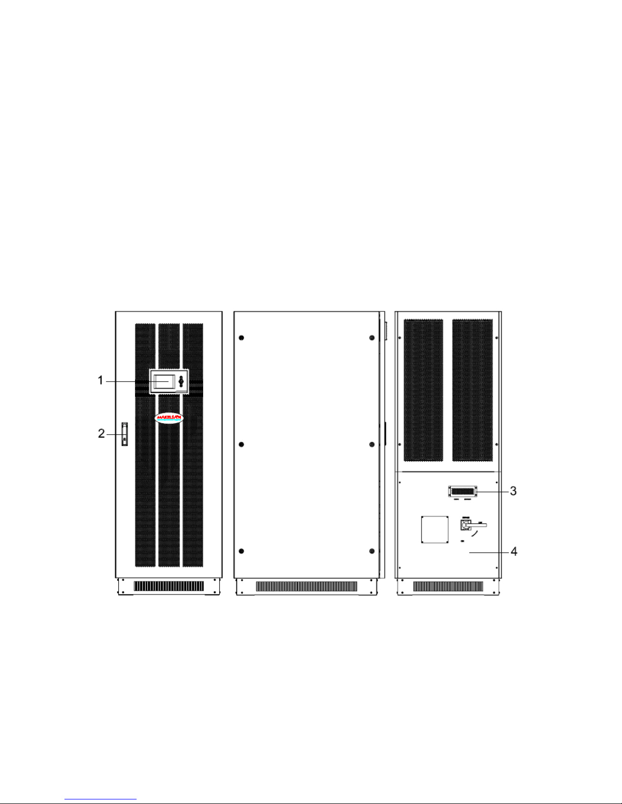
(1) LCD panel
(2) Front lock
(3) Lightning arrester cover plate : Remove cover plate to replace lightning arrester
(4) Bypass and battery terminal cover : Remove cover to operate wire
(5) Fuse box: Input fuse board and Battery fuse board inside, fuse box 1 connect to module 1
(6) Communication module
(7) I/P Switch
(8) Maintenance switch
(9) Maintenance switch cover : Remove cover UPS transfers to Maintenance
(10) Input/output Terminal cover : Remove cover to operate wire
(11) O/P Switch
(12) The input filter capacitor switch : connect capacitor or not
(13) Parallel port 1/2
(14) Lightning arrester
(15) Bypass Switch
(16) Update RS485 port : use to update UPS software
(17) LBS port
(18) Tools box : parallel cable, user manual, switch handle
(19) Power Module 1 : screw top left corner bolt of the module after insert the module,
otherwise the module does not work.
(20) Power Module 2
(21) Power Module 3
(22) Power Module 4
(23) Power Module 5
(24) Power Module 6
(25) Power Module 7
(26) Power Module 8
(27) Power Module 9
(28) Power Module 10
(29) Power Module 11
(30) Power Module 12
(31) Power Module 13
PM SERIES
UDD-SD-125/ Release Date: 20.01.2015/Rev No: 0/Rev. Date:
12
Communication Panel
(1) Communication panel fixed screw
(2) Intelligent slot 1 : insert SNMP card or Dry contact card
(3) Intelligent slot 2 : insert SNMP card or Dry contact card
(4) RS485 port 1/2
(5) BAT_T port 1/2 : connect battery temperature sensor box
(6) Dry contact : Pin1-12Vdc, Pin2- DRY_GENER , Pin7- BP_O, Pin8- BP_S
(7) RS232 port
(8) EPO button
(9) REPO port : Remote EPO connect port
(10) LED indication
(11) Function key
(12) LCD port : connected to LCD panel
PM SERIES
UDD-SD-125/ Release Date: 20.01.2015/Rev No: 0/Rev. Date:
13
Fuse box
(1) Fuse Box 1 : input fuse and battery fuse inbuilt, connect to module 1
(2) Fuse Box 2 : input fuse and battery fuse inbuilt, connect to module 2
(3) Fuse Box 3 : input fuse and battery fuse inbuilt, connect to module 3
(4) Fuse Box 4 : input fuse and battery fuse inbuilt, connect to module 4
(5) Fuse Box 5 : input fuse and battery fuse inbuilt, connect to module 5
(6) Fuse Box 6 : input fuse and battery fuse inbuilt, connect to module 6
(7) Fuse Box 7 : input fuse and battery fuse inbuilt, connect to module 7
(8) Fuse Box 8 : input fuse and battery fuse inbuilt, connect to module 8
(9) Fuse Box 9 : input fuse and battery fuse inbuilt, connect to module 9
(10) Fuse Box 10 : input fuse and battery fuse inbuilt, connect to module 10
(11) Fuse Box 11 : input fuse and battery fuse inbuilt, connect to module 11
(12) Fuse Box 12 : input fuse and battery fuse inbuilt, connect to module 12
(13) Fuse Box 13 : input fuse and battery fuse inbuilt, connect to module 13
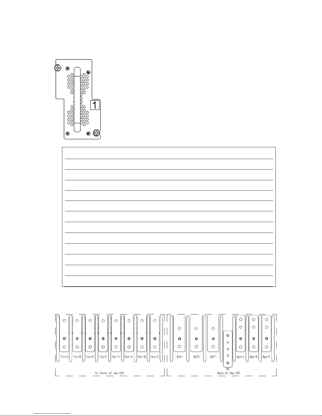
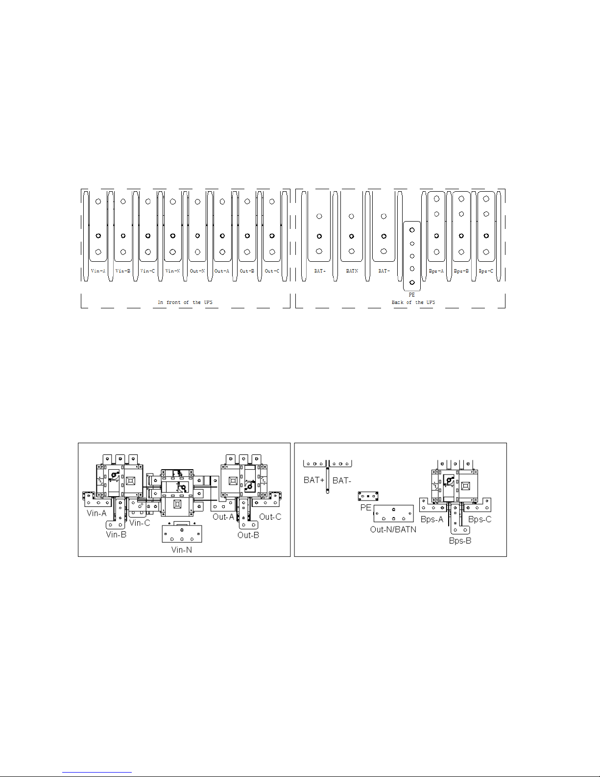
200/320kVA Terminal Block:
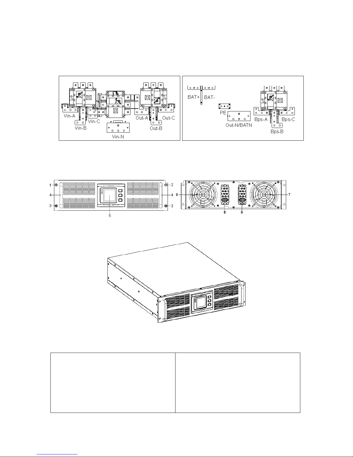
PM SERIES
UDD-SD-125/ Release Date: 20.01.2015/Rev No: 0/Rev. Date:
14
400/520kVA Terminal Block:
In front of the UPS Back of the UPS
3.3 UPS Module Appearance
Front View Rear View
Side View
1. Module left switch screw
2. Module right switch screw
3. Module fixed screw
4. Handle
5. LCD display
6. INV fan
7. PFC fan
8. Module output connector slot
9. Module input connector slot
PM SERIES
UDD-SD-125/ Release Date: 20.01.2015/Rev No: 0/Rev. Date:
15
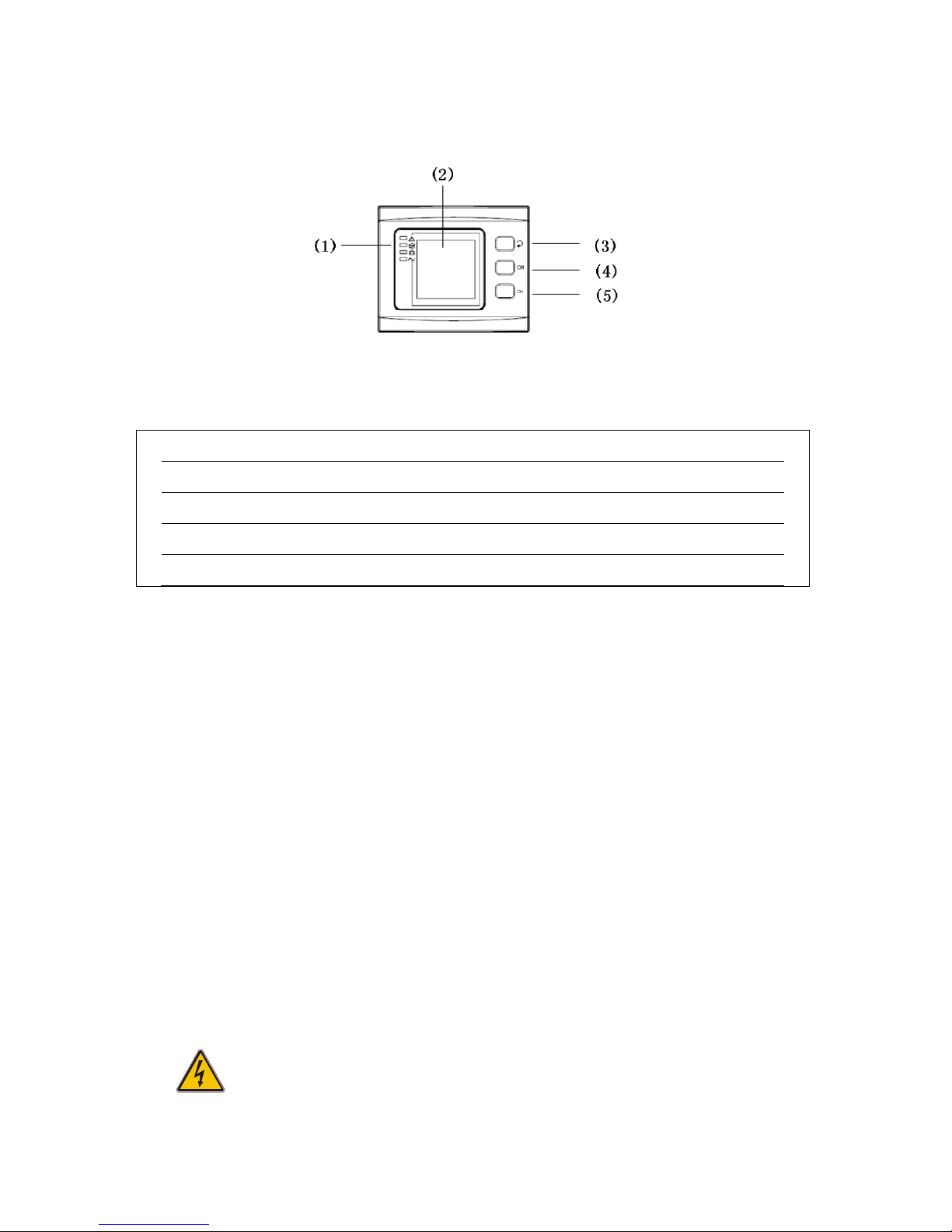
3.4 UPS Module LCD Control Panel
LCD control panel introduction
(1) LED(from top to bottom: “alarm”, “bypass output”, “battery output”, “mains output”)
(2) LCD display
(3) scroll button
(4) Off button
(5) On button
3.5 Installation Notes
NOTE:
Consider for the convenience of operation and maintenance, the space in front and back of the
cabinet should be left at least 100cm and 80cm respectively when installing the cabinet.
• Please place the UPS in a clean, stable environment; avoid the vibration, dust, humidity,
flammable gas and liquid, corrosive. To avoid from high room temperature, a system of room
extractor fans is recommended to be installed. Optional air filters are available if the UPS
operates in a dusty environment.
• The environment temperature around UPS should keep in a range of 0℃~40℃. If the
environment temperature exceeds 40℃, the rated load capacity should be reduced by 12% per
5℃. The max temperature can't be higher than 50℃.
• If the UPS is dismantled under low temperature, it might be in a condensing condition. The UPS
can't be installed unless the internal and external of the equipment is fully dry. Otherwise,
there will be in danger of electric shock.
• Batteries should be mounted in an environment where the temperature is within the required
specs. Temperature is a major factor in determining battery life and capacity. In a normal
installation, the battery temperature is maintained between 15°C and 25°C. Keep batteries
away from heat sources or main air ventilation area, etc.
WARNING!

PM SERIES
UDD-SD-125/ Release Date: 20.01.2015/Rev No: 0/Rev. Date:
16
Typical battery performance data are quoted for an operating temperature between
20°C and 25°C. Operating it above this range will reduce the battery life while
operation below this range will reduce the battery capacity.
• Should the equipment not be installed immediately it must be stored in a room so as to protect
it against excessive humidity and or heat sources.
CAUTION!
An unused battery must be recharged every 6months temporarily connecting the
UPS to a suitable AC supply mains and activating it for the time required for
recharging the batteries.
• The highest altitude that UPS may work normally with full load is 1500 meters. The load
capacity should be reduced when this UPS is installed in place whose altitude is higher than
1500 meters, shown as the following table:
(Load coefficient equals max load in high altitude place divided by nominal power of the UPS)
Altitude(m)
1500
2000
2500
3000
3500
4000
4500
5000
Load coefficient
100%
95%
90%
85%
80%
75%
70%
65%
• The UPS cooling is depending on fan, so it should be kept in good air ventilation area. There
are many ventilation holes on the front and rear, so they should not be blocked by any exotic
obstacles.
3.6 External Protective Devices
For safety reasons, it is necessary to install, external circuit breaker at the input A.C. supply and
the battery. This chapter provides guidelines for qualified installers that must have the
knowledge of local wiring practices for the equipment to be installed.
• External Battery
The UPS and its associated batteries are protected against the effect of over-current through a
DC compatible thermo-magnetic circuit-breaker (or a set of fuses) located close to the
battery.
• UPS Output
Any external distribution board used for load distribution shall be fitted with protective
devices that may avoid the risk of UPS overloaded.
• Over-current
Protection device shall be installed at the distribution panel of the incoming main supply. It
may identify the power cables current capacity as well as the overload capacity of the system.
PM SERIES
UDD-SD-125/ Release Date: 20.01.2015/Rev No: 0/Rev. Date:
17
3.7 Power Cables
• The cable design shall comply with the voltages and currents provided in this section, Kindly
follow local wiring practices and take into consideration the environmental conditions
(temperature and physical support media).
WARNING!
UPON STARTING, PLEASE ENSURE THAT YOU ARE AWARE OF THE LOCATION AND
OPERATION OF THE EXTERNAL ISOLATORS WHICH ARE CONNECTED TO THE UPS
INPUT/BYPASS SUPPLY OF THE MAINS DISTRIBUTION PANEL.CHECK TO SEE IF
THESE SUPPLIES ARE ELECTRICALLY ISOLATED, AND POST ANY NECESSARY
WARNING SIGNS TO PREVENT ANY INADVERTENT OPERATION
• For future expansion purpose, it is economical to install power cable according to the full
rating capacity initially. The diameter of cable is shown bellow:
UPS
cabinet
Cable Dimension
AC Input
AC Output
DC Input
Grounding
200
185
185
120*2
185
320
150*2
150*2
185*2
150*2
520
240*2
240*2
240*3
240*2
CAUTION!
Protective earth cable: Connect each cabinet to the main ground system. For
Grounding connection, follow the shortest route possible .
WARNING!
FAILURE TO FOLLOW ADEQUATE EARTHING PROCEDURES MAY RESULT IN
ELECTROMAGNETIC INTERFERENCE OR IN HAZARDS INVOLVING ELECTRIC
SHOCK AND FIRE
3.8 Power Cable Connect
Once the equipment has been finally positioned and secured, connect the power cables as
described in the following procedure.
Verify the UPS is totally isolated from its external power source and also all power isolators of
the UPS are open. Check to see if they are electrically isolated, and post any necessary warning
signs to prevent their inadvertent operation.
Open the UPS terminal panel; remove the cover of terminals for wiring easily.
PM SERIES
UDD-SD-125/ Release Date: 20.01.2015/Rev No: 0/Rev. Date:
18
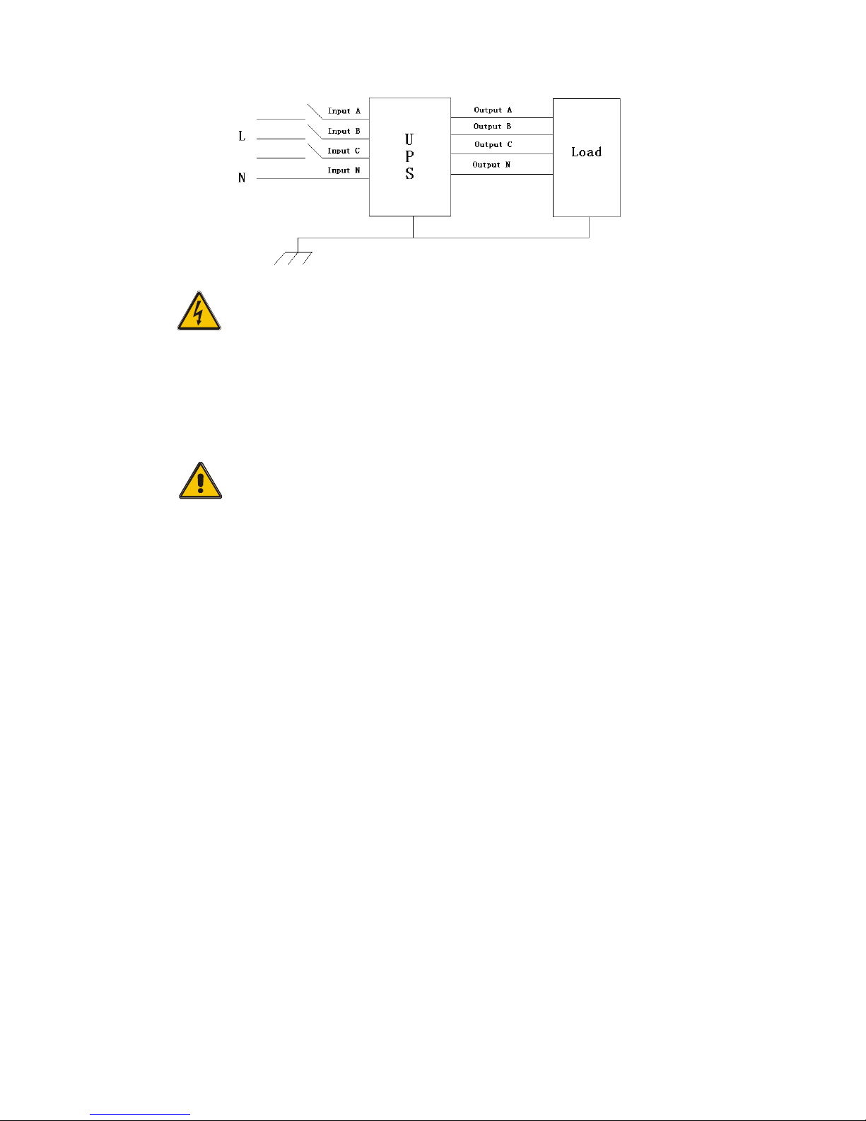
200/320kVA Terminal Block:
Terminal sequence from left to right: input phase A(L1),input phase B(L2),input phase
C(L3),input Neutral line, output Neutral line, output phase A(L1), output phase B(L2), output
phase C(L3);battery positive, battery Neutral, battery negative, ground, bypass input phase
A(L1),bypass input phase B(L2),bypass input phase C(L3).
520kVA Terminal Block:
In front of the UPS Back of the UPS
Terminal sequence from left to right: input phase A(L1),input phase B(L2),input phase
C(L3),input Neutral line, output phase A(L1), output phase B(L2), output phase C(L3);battery
positive, battery negative, output and battery Neutral, ground, bypass input phase A(L1), bypass
input phase B(L2),bypass input phase C(L3).
Choose appropriate power cable. (Refer to the table above) and pay attention to the diameter of
the connection terminal of the cable that should be greater than or equal to that of the
connection poles;
PM SERIES
UDD-SD-125/ Release Date: 20.01.2015/Rev No: 0/Rev. Date:
19
WARNING!
If the load equipment is not ready to accept power on the arrival of the
commissioning engineer then ensure that the system output cables are safely
isolated at their ends
Connect the safety earth and any necessary bonding earth cables to the copper
earth screw located on the floor of the equipment below the power connections.
All cabinets in the UPS must be grounded properly.
CAUTION!
The earthing and neutral bonding arrangement must be in accordance with local
and national codes of practice.
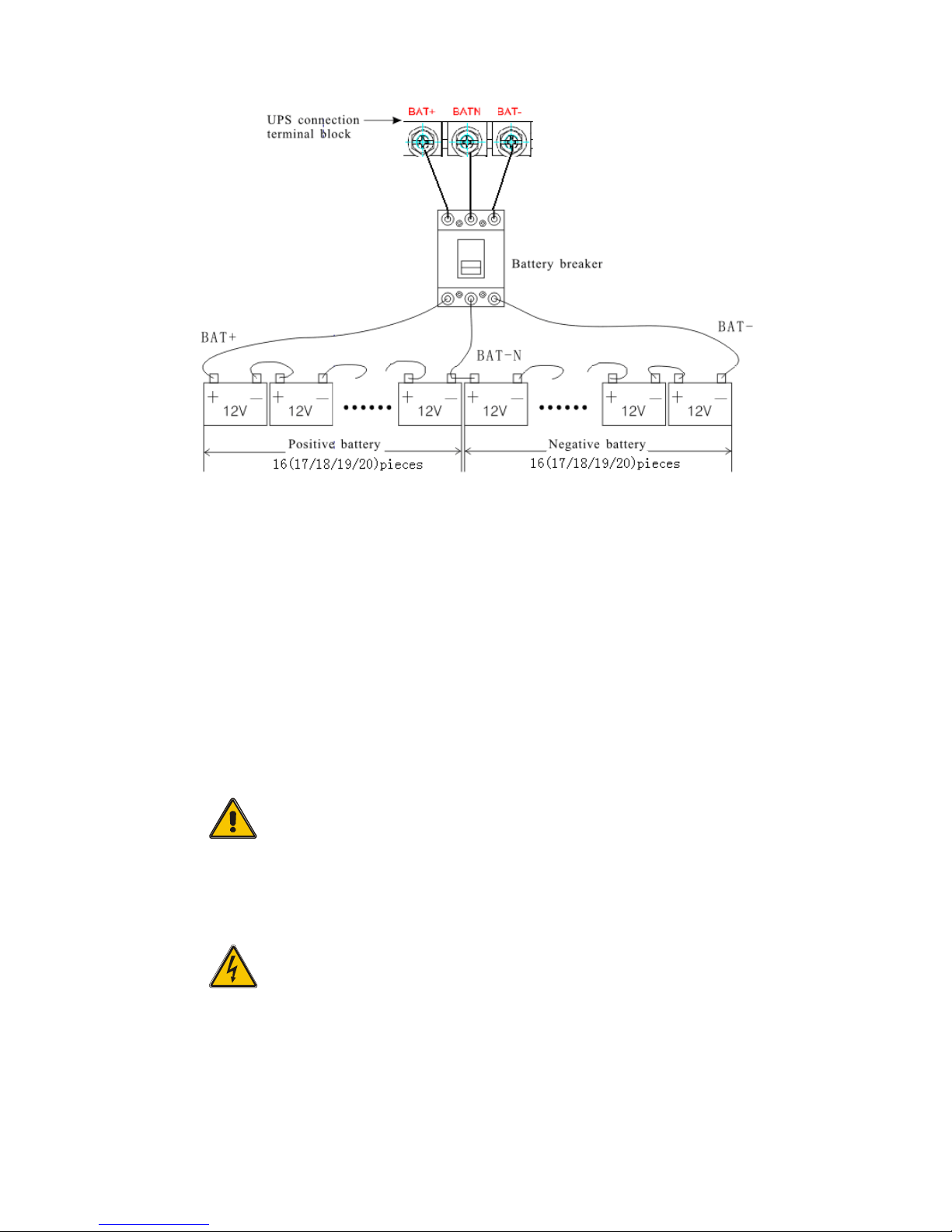
3.9 Battery Connection
The UPS adopts positive and negative double battery framework, total 32(optional
34/36/38/40) in series. A neutral cable is retrieved from the joint between the cathode of the
16th (17th/18
th
/19th/20
th
) and the anode of the 17th (18th/19
th
/20th/21
th
) of the batteries. Then
the neutral cable, the battery Positive and the battery negative are connected with the UPS
respectively. The battery sets between the Battery anode and the neutral are called positive
batteries and that between neutral and cathode are called negative ones. The user can choose
the capacity and the numbers of the batteries according to their desire.
PM SERIES
UDD-SD-125/ Release Date: 20.01.2015/Rev No: 0/Rev. Date:
20
NOTE:
The BAT+ of the UPS connect poles is connected to the anode of the positive battery, the BAT-N
is connected to the cathode of the positive battery and the anode of the negative battery, the
BAT- is connected to the cathode of the negative battery.
Factory setting of the long-run unit is battery quantity---32pcs, battery capacity---12V65AH.
When connecting 32/34/38/40 batteries, please re-set desired battery quantity and its capacity
after UPS starts at AC mode. Charger current could be adjusted automatically according to
battery capacity selected. All related settings can be done through LCD panel or monitoring
software.
CAUTION!
Ensure correct polarity battery string series connection. I.e. inter-tier and inter
block connections are from (+) to (-) terminals.
Don’t mix batteries with different capacity or different brands, or even mix up
new and old batteries, either.
WARNING!
Ensure correct polarity of string end connections to the Battery Circuit
Breaker and from the Battery Circuit Breaker to the UPS terminals i.e. (+) to
(+) / (-) to (-) but disconnect one or more battery cell links in each tier. Do
not reconnect these links and do not close the battery circuit breaker unless
authorized by the commissioning engineer.
 Loading...